
Summary of Contents for Micro-Comm S4500
- Page 1 Micro-Comm RTU32 PLC User’s Reference Manual (S4500, M1500, M550, M555, M1550, M1650, M655, M1600) Revised: July 22, 2019 Copyright © 2019 Micro-Comm, Inc.
-
Page 2: Table Of Contents
Table of Contents S4500 PLC .................................. 3 S4500 Specifications and Sales Information ......................4 M1500 PLC ................................. 6 M1500 Specifications and Sales Information ....................... 7 M550 PLC ................................... 9 M550 Specifications and Sales Information ....................... 10 M555 PLC ................................. 11 M555 Specifications and Sales Information ....................... -
Page 3: S4500 Plc
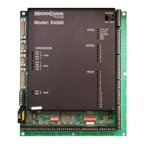
S4500 PLC The S4500 is a fourth-generation Micro-Comm RTU/PLC built on the S4000 motherboard utilizing a new daughterboard with a faster 32bit microprocessor and more RAM and FLASH memory. As a result, the S4500 software has the following enhanced features: Changes and Enhanced Features: •... -
Page 4: S4500 Specifications And Sales Information
Phone line, & fiber oPtic communications simultaneous rtu-rtu & ctu-rtu communications Plug-in terminal blocks he S4500 PLC is a reliable, full-fea- tured Progammable Logic Controller. It is a “smart” unit providing both programmability and interchange- ability through a plug-in memory module. As... - Page 5 L17 - 0-300 baud radio modem • Plug In RF MODEM L17A - 0-600 baud radio modem 0-300, 600, 1200 BAUD Micro-Comm, Inc. • 15895 S Pflumm Rd • Olathe, KS 66062 • (913) 390-4500 • fax: (913) 390-4550 • www.micro-comm-inc.com - 5 -...
-
Page 6: M1500 Plc
M1500 PLC The M1500 is a fourth-generation Micro-Comm controller built with the processor daughterboard from the S4500 (32bit microprocessor). The M1500 is physically much smaller than the S4500, having the reduced I/O count listed below: I/O capabilities: Relay outputs Open-collector outputs (COM1 pins used for radio switching) -
Page 7: M1500 Specifications And Sales Information
M1500 Specifications and Sales Information programmable logiC Controller (plC) model m1500 fully programmable with plug-in memory module miCro-Comm, modbus rtu and allen-bradley df1 protoCols optional front panel display & expandable i/o radio, phone line, & fiber optiC CommuniCations simultaneous rtu-rtu &... - Page 8 L17A - 0-600 baud radio modem • COM2 (pin 4) 2.5A L17B - 1200 baud radio modem • COM3 (12V) 2.5A Micro-Comm, Inc. • 15895 S Pflumm Rd • Olathe, KS 66062 • (913) 390-4500 • fax: (913) 390-4550 • www.micro-comm-inc.com - 8 -...
-
Page 9: M550 Plc
M550 PLC The M550 is a fourth-generation Micro-Comm controller built with the processor daughterboard from the S4500 (32bit microprocessor). The M550E is a version of the M550 with an Ethernet port in place of the COM2 serial port. The M550 is physically much smaller than the S4500, having the reduced I/O count listed... -
Page 10: M550 Specifications And Sales Information
• 1MB Serial FLASH, Configuration Gas and Oil Monitoring Power Source Electrical Distribution Monitoring • 12 VDC Power Input Micro-Comm, Inc. • 15895 S Pflumm Rd • Olathe, KS 66062 • (913) 390-4500 • fax: (913) 390-4550 • www.micro-comm-inc.com - 10 -... -
Page 11: M555 Plc
M555 PLC The M555 is a fifth-generation Micro-Comm controller similar to the M550E PLC, but with a faster processor, more memory, faster ethernet port and 2 additional communication ports. I/O capabilities: Open-collector outputs (COM1 pins used for radio switching) On-board 12bit analog inputs Temperature (0.25 to 4.75v = -50C to +150C = -58F to +302F),... -
Page 12: M555 Specifications And Sales Information
M555 Specifications and Sales Information programmable logiC Controller (plC) model m555 fully programmable with plug-in memory module miCro-Comm, modbus rtu and allen-bradley df1 protoCols optional front panel display & expandable i/o radio, phone line, ethernet & fiber optiC CommuniCations simultaneous rtu-rtu & Ctu-rtu... - Page 13 • Field Wiring - Use Copper Conductors Only, 60°C Wire Range, 12-26 AWG Wire Strip Length, 0.310” Recommended Tightening Torque, 0.79 N-m / 7.0 lb-in. Micro-Comm, Inc. • 15895 S Pflumm Rd • Olathe, KS 66062 • (913) 390-4500 • fax: (913) 390-4550 • www.micro-comm-inc.com - 13 -...
-
Page 14: M555 Installation Requirements
M555 Installation Requirements The installation of the M555 shall comply with all local and national fire and electrical codes, i.e. NFPA 70, National Electric Code. In order to provide proper fire and electrical shock pro- tection, the M555 shall be powered from an isolated power source, use 14 AWG supply wiring provided with an 8A over current protection fuse. -
Page 15: M555 Lithium Battery Replacement
Caution: the lithium battery used in this device may present a fire or chemical burn hazard if mistreated. Do not recharge, disassemble, heat above 100°C (212°F) or incinerate. Replace battery with Panasonic, Part No. BR-2/3A or Micro-Comm Part No. BAT-004-3 only. Use of another battery may present a risk of fire or explosion. -
Page 16: M1550 Plc
M1550 PLC The M1550 is a fifth-generation Micro-Comm controller similar to the M1500 PLC, but with a faster processor, more memory, ethernet port and an additional COM4 port. I/O capabilities: Form C Relay Outputs Open-collector outputs (COM1 pins used for radio switching) -
Page 17: M1550 Specifications And Sales Information
M1550 Specifications and Sales Information programmable logiC Controller (plC) model m1550 fully programmable with plug-in memory module miCro-Comm, modbus rtu and allen-bradley df1 protoCols optional front panel display & expandable i/o radio, phone line, & fiber optiC CommuniCations simultaneous rtu-rtu &... - Page 18 L17B - 1200 baud FSK modem • Internal Battery Lithium 3V, 1200mAh, 2/3A Size (Real-Time Clock and NVRAM) Micro-Comm, Inc. • 15895 S Pflumm Rd • Olathe, KS 66062 • (913) 390-4500 • fax: (913) 390-4550 • www.micro-comm-inc.com - 18 -...
-
Page 19: M1550 Installation Requirements
M1550 Installation Requirements The installation of the M1550 shall comply with all local and national fire and electrical codes, i.e. NFPA 70, National Electric Code. In order to provide proper fire and electrical shock pro- tection, the M1550 shall be powered from an isolated power source, use 14 AWG supply wiring provided with an 8A over current protection fuse. -
Page 20: M1550 Lithium Battery Replacement
Caution: the lithium battery used in this device may present a fire or chemical burn hazard if mistreated. Do not recharge, disassemble, heat above 100°C (212°F) or incinerate. Replace battery with Panasonic, Part No. BR-2/3A or Micro-Comm Part No. BAT-004-3 only. Use of another battery may present a risk of fire or explosion. -
Page 21: M1650, M655 And M1600 Plc
M1650, M655 and M1600 PLC The M1650 and M655 are sixth-generation Micro-Comm controllers similar to the M1550/M555 PLCs, but with the additional of a built-in Ethernet coprocessor (uLynx) in place of the COM5 Ethernet found in the older PLCs. The new uLynx Ethernet module provides simultaneous master connections to other controllers as well as multiple slave connections utilitizing Micro- Comm CTU32, Modbus/TCP and Ethernet/IP protocols. -
Page 22: M1650 Specifications And Sales Information
Communications Gas and Oil Monitoring Electrical Distribution Monitoring • COM1, Radio Port, RS-232 Optional RF MODEM, 0-600 or 1200 baud Micro-Comm has been providing Local Control: • COM2, Display,/Programming, RS-232 process control solutions for more than Water Booster Pump Stations •... - Page 23 L17B - 1200 baud FSK modem • Internal Battery Lithium 3V, 1200mAh, 2/3A Size (Realtime Clock and NVRAM) Micro-Comm, Inc. • 15895 S Pflumm Rd • Olathe, KS 66062 • (913) 390-4500 • fax: (913) 390-4550 • www.micro-comm-inc.com - 23 -...
-
Page 24: M655 Specifications And Sales Information
M655 Specifications and Sales Information PROGRAMMABLE LOGIC CONTROLLER (PLC) MODEL M655 FULLY PROGRAMMABLE WITH PLUG-IN MEMORY MODULE MICRO-COMM, MODBUS RTU AND ALLEN-BRADLEY DF1 PROTOCOLS OPTIONAL FRONT PANEL DISPLAY & EXPANDABLE I/O SERIAL AND ETHERNET COMMUNICATIONS SIMULTANEOUS RTU-RTU & CTU-RTU COMMUNICATIONS... - Page 25 • Field Wiring - Use Copper Conductors Only, 60°C Wire Range, 12-26 AWG Wire Strip Length, 0.310” Recommended Tightening Torque, 0.79 N-m / 7.0 lb-in. Micro-Comm, Inc. • 15895 S Pflumm Rd • Olathe, KS 66062 • (913) 390-4500 • fax: (913) 390-4550 • www.micro-comm-inc.com - 25 -...
-
Page 26: M1600 Specifications And Sales Information
Gas and Oil Monitoring Communications Electrical Distribution Monitoring • COM1, Radio Port, RS-232 Optional RF MODEM, 0-600 or 1200 baud Micro-Comm has been providing Local Control: • COM2, Display,/Programming, RS-232 process control solutions for more than Water Booster Pump Stations •... - Page 27 L17B - 1200 baud FSK modem • Internal Battery Lithium 3V, 1200mAh, 2/3A Size (Realtime Clock and NVRAM) Micro-Comm, Inc. • 15895 S Pflumm Rd • Olathe, KS 66062 • (913) 390-4500 • fax: (913) 390-4550 • www.micro-comm-inc.com - 27 -...
-
Page 28: Expansion I/O Module Setup
Note: The Micro-Comm I/O polling loop was originally designed to extend the on-board physical I/O of an S4500. It starts with locations that are outside the range of the S4500 on-board I/O: writing DO17-DO80, AO1-AO16 and reading DI17-DI80, AI17-AI32. - 28 -... -
Page 29: Communication Port Pinouts
19 - /PTT 20 - DTR (12VDC) Note: The M555 and M655 use the RS-232 driver output for this pin (not 12VDC). 21 - DO1 (open collector outputs - not available on the S4500) 22 - DO2 23 - DO3... -
Page 30: Display Module Operation
Display Module Operation The Micro-Comm display module allows the operator to view up to 32 analog levels, 32 discrete input conditions, 32 discrete output conditions, change up to 32 stop/start setpoints, change all 8 output timer settings (both on and off delays) , view/change the user variables (X1-X32) and view/change user memory with up to 128 screens. -
Page 31: Rtu32 Protocol I/O Mapping
RTU32 PLC. When being polled from a C2000 or Card Rack CTU, the older “Enhanced Control Card” protocol will be used. The table below shows how the physical I/O in the S4500 is mapped for both protocols: RTU32 Protocol Layout... - Page 32 The table below shows how the physical I/O on the M1500 or M1550 is mapped for both proto- cols: RTU32 Protocol Layout M1500 Station Address #1 Relay outputs DO1-DO4 Discrete outputs 1-4 Discrete inputs DI1-DI8 Discrete inputs 1-8 EDI Modules 1,2 DI17-DI48 Expansion inputs 1-32 Analog inputs AI1-AI4 Analog inputs 1-4...
-
Page 33: Allen-Bradley Df1 And Modbus Protocol Support
Allen-Bradley DF1 and Modbus Protocol Support All RTU32 PLCs can use Allen-Bradley DF1 or Modbus RTU protocols. The information below describes what protocol options are supported and how the data is mapped to physical I/O or memory locations in the PLC: DF1 Specifications Data Link Layer Protocol: DF1 Half-Duplex Master/Slave, DF1 Full-Duplex or DF1 Radio Modem... -
Page 34: Allen-Bradley Ethernet/Ip And Modbus/Tcp Protocol Support
Allen-Bradley Ethernet/IP and Modbus/TCP Protocol Support When RTU32 PLCs are connected using the µLynx Ethernet Coprocessor (or then have an internal µLynx like the M1650 or M655), they can be communicated with using Allen-Bradley SLC PCCC, CIP Data Table Messages, Generic CIP Messages or Modbus /TCP protocol. -
Page 35: Rtu Configuration 32
Program Installation A new version of RTU Configuration is required for programming the S4500 and later 32 bit PLCs. For lack of a better name, this new program is called “RTU Configuration 32”. Throughout this manual the program will be called “RTU Configuration 32”... -
Page 36: Rtu Information Screen
RTU Information Screen The RTU Information screen contains version, date, checksums, user information, address switch settings as well as a picture of the RTU. This information about the RTU will be available after the user has read the Personality Module. The Job Name and Site Name fields can be changed if necessary and the User Name and Last Pro- grammed will reflect who made the most recent change. -
Page 37: Configuration Parameters
Configuration Parameters The screen below shows a sample RTU Configuration dialog box. This screen is where all the operational param- eters stored in the Personality Module can be changed (radio communications parameters, output timer settings, automote control settings and stop/start setpoints). To retrieve the personality data from an RTU, click on the blue down arrow icon or select Read Personality Data from the Transfer menu. - Page 38 When this option is checked, the RTU will turn on the internal 600 (or 110) baud radio modem. Leave this box un-checked when using an external radio modem. Note: The S4500 and M1500 RTUs do not have hardware support for this option. Only M550 and later RTUs.
- Page 39 The timer settings control how long the RTU will wait to energize or de-energize a relay output when it has been told to come on or go off. These timers will always be used regardless of the mode of operation - Micro-Comm CTU control, Script Lan- guage, Modbus or DF1.
- Page 40 The options for the M555 and M1550 ethernet port are configured with the screen shown below: Protocol The protocol selection for the Ethernet Port (COM5). Options include Micro-Comm RTU32, DF1 Half- Duplex Slave, DF1 Half-Duplex Master, DF1 Full-Duplex, DF1 Radio Modem, Modbus RTU Slave, Modbus RTU Master, Modbus/TCP, Micro-Comm CTU32, Web Server, EtherNet/IP SLC and EtherNet/IP CLX (compact logix).
-
Page 41: Analog Labels And Scaling Factors
When analog levels are displayed, the offset is first added to the raw analog value and the result is then multiplied by the range value. (This matches the Micro-Comm SCADAview program). A Range/Preset calculator (shown below) can be displayed by right-clicking and selecting the menu option. -
Page 42: Output Timer Labels
To change the 20 character output timer display labels, click on the toolbar clock icon or select “Display Labels” from the View menu. The labels are retrieved/sent to the RTU during reading/writing of the configuration data. These labels are normally used for pumps and provide both ON and OFF delays entered on the Micro-Comm Display Module. -
Page 43: Stop/Start Setpoint Labels
Stop/Start Setpoint Labels Stop/Start labels are used on the Display Module to allow the operator to change operational parameters such as Pump Stop/Start setpoints, High/Low alarms and Pump Restore/Cutoffs. Along with the 20 character label is a selection for what type of setpoint (Stop/Start, High/Low etc.) and which analog input # will be used for scaling and units. -
Page 44: Variable Labels
X Variable Labels User variables are the 16-bit unsigned integer X1-X32 script language variables that can be used for any purpose. By entering a label in the User Variable Labels setup screen, the current value will be shown and can be changed on the Display Module. -
Page 45: Discrete I/O Labels
Discrete I/O Labels Labels for both 32 discrete inputs and 32 discrete outputs are user defined. These labels may be used to display pump calls, pump runs, valve positions, alarms etc. A 12-character label is used to name the input or output along with a 6-character ON label and a 6-character OFF label to describe the on or off state. -
Page 46: User Memory Screens
The user memory screens are accessed by arrowing all the way down to the bottom row of the Micro-Comm dis- play. The left and right arrows will then select the desired user memory screen. -
Page 47: User Memory Table
User Memory Table The User Memory Table screen provides the capability of reading and updating all user memory locations as well as saving and loading a comma seperated (.CSV) database file. This file could then be used for data logging/ trending or saving a backup copy of important data such as flow totals, runtimes etc. -
Page 48: Rtu Script Language Editor
RTU Script Language Editor To enter or edit the Script Language Code, click on the script icon in the tool palette or select “Script Editor” from the View menu. Script language can be retrieved from the RTU by clicking the Read button shown at the bottom of the editor window or by selecting Read RTU Script from the Transfer menu. -
Page 49: Commented Script / Revision Editor
Commented Script / Revision Editor If the option “Use Commented Script for Revision Notes” is turned on in the preferences, this screen will be filled in with the current commented script including all subroutines. It can then be programmed into the personal- ity module with the “Program”... -
Page 50: Data Table Viewer
Data Table Viewer The Data Table Viewer screen allows the operator to see and change I/O variables, User variables and the Stop/ Start setpoints in real-time when connected to an RTU. This screen can be very useful when debugging script lan- guage code. -
Page 51: Display Module Emulator
Display Module Emulator The display module is an optional hardware component to a Micro-Comm RTU which allows an operator to see levels and change setpoints. While programming with RTU Configuration 32 software, the operator can use the Display Module Emulator screen to see what the display module would show. This can be very useful since both the display module and the programming software may be using the same com port on the RTU. -
Page 52: Debug Terminal
Debug Terminal The Debug Terminal screen allows the user to interact directly with the RTU over the programming port (COM2- COM5) or with other third-party serial equipment. It will display incoming data using ASCII, Modbus or DF1 mode based on the “Display Mode” selection in the lower-left hand corner of the screen. Protocol analysis of master messages (requests) can be done by selecting “RTU32-Decode”, “Modbus-Decode”...
Need help?
Do you have a question about the S4500 and is the answer not in the manual?
Questions and answers