
Summary of Contents for Quantum Opus Opus One
- Page 1 Opus One Superconducting Nanowire Single- Photon Detection System Installation and Operation Manual March 28, 2020 Quantum Opus, LLC 22241 Roethel Drive Suite A Novi, MI 48375 1-269-248-1004...
-
Page 2: Table Of Contents
....... 3 Electronics Unit Installation 3.1 Connecting the electronics to the Opus One ..... . 12 4 System Operation 4.1 Cool Down Procedure... - Page 3 (1) year from the date of shipment. Service For warranty service or repair, this product must be returned to a Quantum Opus authorized ser- vice facility. Some components may be serviceable directly from the supplier. Contact Quantum Opus before returning this product for repair.
- Page 4 (possibly significant) to persons or property. Do not proceed past a WARNING notice until the indicated conditions are fully understood and met. If there is any question about proper performance of the procedure or practice, contact Quantum Opus support for guidance.
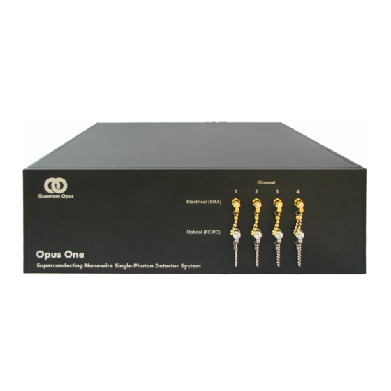
- Page 5 Opus One Figure 1: Photo of a typical four-channel Opus One unit containing four superconducting nanowires, cryogenic vacuum system, and fiber optic couplers. Various configurations are available with up to 32 detector channels in the above 19-inch rack configuration (3U height). Specific options and configurations may vary.
-
Page 6: Introduction
Compressor Unit Compressor Power Cooling water Figure 2: Nanowire system schematic showing Opus One head unit, electronics unit, and com- pressor with all connections. 1.1 Overview The nanowire system has three main physical components, as identified in Figure 2: 1. The “Electronics Unit” that provides system thermometry and nanowire device control and monitoring. - Page 7 Opus One 3. The “Compressor Unit” that provides the high-pressure, high-purity helium and valve con- trol signals to obtain and maintain the low temperatures required for superconducting nanowire operation.
-
Page 8: Installation
3. Determine the best location for the electronics unit noting that it is intended to be operated either directly above or below the Opus One unit to minimize the introduction of noise between the electronics and the Opus One unit. -
Page 9: Compressor Unit Installation
WARNING Do not install the helium lines to the Opus One until instructed to do so in the order given below. Installation of the helium lines in the wrong order, or to the wrong ports, may require factory repair of the Opus One unit. - Page 10 2. Carefully remove the Opus One unit from its packaging. Note that the unit has a significant fraction of its weight toward the back. 3. Remove any protective wrapping around the Opus One unit and on the front panel.
- Page 11 Opus One Figure 3: Rear view of the Opus One detector unit showing a suggested lift point for installation.
-
Page 12: Electronics Unit Installation
fiber connections. Slightly tighter than finger-tight connections are recom- mended for SMA connections. Overtightening the connectors may loosen the internal connectors in the Opus One unit or cause damage to the connectors, damage to cables, or increased system losses and noise. - Page 13 Low jitter c 10-bit low- Front and back views of 16-channel nanowire d Figure 4: A typical 16-channel Quantum Opus SNSPD Control and Readout Electronics electronics module (QOELEC) module. Configuration may vary by system. Non-volatil current val 5.
-
Page 14: System Operation
(sometimes very significant) during pumping. Inadequate line length can cause unsafe forces on the pump, pumping lines, or Opus One unit and can cause equipment to be damaged or to move in undesired ways (e.g., tip over, fall off of shelving). - Page 15 Follow the vacuum pump manufacturer’s recommended procedure for starting the pump and evacuating the pump tube. f) Slowly open the vacuum valve on the Opus One unit. The valve is fully open once rotated counterclockwise approximately two (2) full turns. The valve should remain open and the pump on until the system has reached 50 K.
-
Page 16: Warm Up Procedure
(typically below 2.5 K). The cool-down takes approximately three (3) hours from the time the compressor is turned on. 9. The Opus One devices are now ready to be used. Refer to Section 5.1. 4.2 Warm Up Procedure WARNING Ensure the system has been turned off... -
Page 17: Detector Operation
Section 5.2. 4. Setting the Device Bias: With the fiber input on the Opus One, gradually increase the device bias until the dark counts are at the highest acceptable level (typically a few hundred counts per second). -
Page 18: Web Interface Example
Opus One in the measured count rate. Scientists at Quantum Opus enjoy helping you optimize the system for your application, so please reach out to us for any desired assistance. NOTE The nanowires are polarization sensitive and will only achieve peak detection efficiency for photons at the optimal polarization. - Page 19 Opus One Increase Bias Press the plus (+) button or the (++) to increase the bias current. The (+) button has a bias increment of approximately 1% of the present bias setting, while the (++) button has a bias increment of approximately 10%. Holding either button will rapidly increase the bias.
-
Page 20: Troubleshooting
3. Tighten the SMA connectors on the QOELEC and the Opus One just tighter than hand- tight (very gently tighten with an 8-mm wrench). If this connection is slightly loose, the noise can be significantly worse.
Need help?
Do you have a question about the Opus One and is the answer not in the manual?
Questions and answers