
Summary of Contents for Hawksley HAEMATOSPIN 1400
- Page 1 HAEMATOSPIN 1400 (AUTOMATIC BRAKING) 01400-00 Instruction Manual 240 Volt PART NUMBER FOR THIS MANUAL 21849-00...
-
Page 2: Table Of Contents
INDEX Section Page No. 1. Company Information Controls Diagram Controls and Symbols Instructions for Use 5-10 Ordering Information 11-12 QC Test Report IEC 601 Safety test report Specifications Technical Description 16-17 10 Warranty & Service 11 Trouble shooting guide 12 Customer/user information 13 Declaration of Conformity INDEX OF FIGURES Figure... -
Page 3: Company Information
COMPANY INFORMATION Hawksley and Sons Limited Marlborough Road Lancing Business Park Lancing West Sussex, BN15 8TN England Tel.: +44 (0) 1903 752815 Fax: +44 (0) 1903 766050 Website: www.hawksley.co.uk Email: enquires@hawksley.co.uk WRITTEN BY: D. GROVE DATE ISSUE REVISION PAGE APPROVED BY: K.WILLIAMS... -
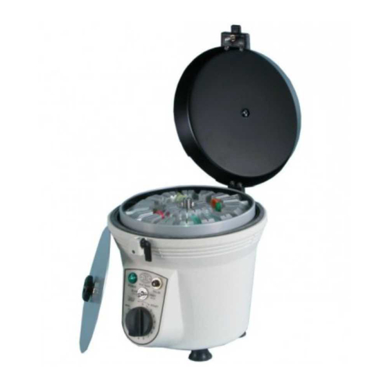
Page 4: Controls Diagram
2. CONTROLS DIAGRAM 1. Power Cord 2. Power Cord Fused Input Socket 3. Lid Lock Assembly 4. Power Indicator 5. Pulse Switch 6. Timer Figure 1 HAEMATOSPIN 1400 WRITTEN BY: D. GROVE DATE ISSUE REVISION PAGE APPROVED BY: K.WILLIAMS 13/09/10... - Page 5 3. CONTROLS & SYMBOLS Lid Locked Lid Unlocked Locking lever in Locking lever in DOWN position. UP position. Switch interlock Switch interlock disengaged. engaged Power Cord connection Fused Input Socket Power cord and moulded Fuses 3.15 Amp (F). socket. Caution: Isolate from In accordance with power source before international colour codes:-...
-
Page 6: Instructions For Use
4. INSTRUCTIONS FOR USE INSTALLATION: Inspect the packaging for damage. If you suspect damage to the device, notify the supplier or manufacturer immediately quoting model and serial number. Unpack the machine and check the parts against the following list. Instruction Manual Haematospin 220/240 volt 24 Place Haematocrit Rotor &... - Page 7 4 . INSTRUCTIONS FOR USE (cont'd) TUBE SAMPLE PREPARATION 1. Capillary tubes used for centrifugation must conform to British Standard BS 4316 to withstand the forces of centrifugation and give accurate results. Please ensure that the tubes to be used are marked on the packaging "BS4316"...
- Page 8 4. INSTRUCTIONS FOR USE (cont'd.) CENTRIFUGE OPERATION Ensure the timer is in the ZERO position. Connect the power cord to the inlet socket and a convenient power source. The green Power Indicator Lamp will illuminate. Close the lid and ensure that the lever is in the LOCKED position. Set the desired run time.
- Page 9 4. INSTRUCTIONS FOR USE (cont'd.) MICRO-HAEMATOCRIT READER Position the tube in the slot so that the base line of the Reader intersects the base of the red cells Move the sliding tube holder left or right until the top line intersects the top of the plasma. Adjust the knob so that the middle line intersects the top of the red cells.
- Page 10 4. INSTRUCTIONS FOR USE (cont'd.) ROTOREADER After centrifugation unscrew the and remove the rotor lid from the rotor. Push the ROTOREADER firmly on to the central spindle. Rotate the centrifuge rotor to bring the required tube to be read nearest to you and restrain from further movement by holding rotor edge.
- Page 11 Re-attach the rotor to the centrifuge using the two fixing screws, taking care not to damage or scratch the rotor surface. Replace the rotor lid only to finger tightness. The use of other than genuine Hawksley replacement parts will void all performance claims and warranties.
-
Page 12: Ordering Information
5 ORDERING INFORMATION CENTRIFUGES (EXCLUDING ROTORS) 01400-00 Haematospin 1400 220V/240V 01401-00 Haematospin 1400 110V/115V 01410-10 Haematospin Vetspin Dual Speed 220V/240V ROTORS (Capillary Tubes length 75mm 75 цl) 01971-00 Rotor Haematocrit 24 Place (Capillary Tubes length 75mm 75 цl 01986-00 Rotor Combi 16 way and Micro Tubes 1.5 to 2ml) - Page 13 ORDERING INFORMATION (cont’d) ACCESSORIES 01502-00 Reader 01503-00 Cristaseal (Box 10 Trays) 01504-00 Rim Seal Gasket (Pkt 20) 01560-00 Rotoreader And Magnifier 01561-00 Magnifier 01562-00 Rotoreader 01603-00 Capillary Tubes Heparinised 75mm (Box 10 X 100) 01604-00 Capillary Tubes Plain 75mm (Box 10 X 100) 01605-00 Capillary Tubes Heparinised 75mm(Box 1000) 01606-00...
-
Page 14: Qc Test Report
6. QC TEST REPORT UNIT Haematospin 1400 CATALOGUE NO 01400-00 SERIAL NO......BATCH NO..VOLTS 240 MOTOR NO......PCB NO………………… CARD NO....QC BY....... DATE....………… TEST REPORT TICK 1. Lid catch and switch adjustment ..TICK 2. Timer operation .. -
Page 15: Iec 601 Safety Test Report
IEC 601 Safety test report WRITTEN BY: D. GROVE DATE ISSUE REVISION PAGE APPROVED BY: K.WILLIAMS 13/09/10... - Page 16 Body - White polyester powder coated Lid - Black Sparkle polyester powder coated All specifications are accurate at the time of printing. In line with Hawksley's policy of continuous improvement, the right to modify the product specifications described is reserved, without advance notice.
-
Page 17: Technical Description
TECHNICAL DESCRIPTION SYSTEM BLOCK DIAGRAM Fig 2 WRITTEN BY: D. GROVE DATE ISSUE REVISION PAGE APPROVED BY: K.WILLIAMS 13/09/10... - Page 18 9. TECHNICAL DESCRIPTION (cont'd) The device is constructed within a purpose-designed enclosure which houses the motor, PCB, timer, power indicator, fused inlet socket and ancillary components. See Fig. 2 System block diagram. ITEM DESCRIPTIONS MOTOR A series wound open frame type, fitted with high-speed precision bearings and balanced armature.
-
Page 19: Warranty & Service
With good housekeeping and regular servicing this device should give trouble-free operation for many years. The device should be serviced every 12 months. Details are available from Hawksley & Sons SERVICE DEPARTMENT on Tel : +44 (0)1903 752815 Fax : +44 (0)1903 766050 or email enquiries@hawksley.co.uk. -
Page 20: Trouble Shooting Guide
11. TROUBLE SHOOTING GUIDE In the event of any fault condition, switch off and disconnect the centrifuge from the power supply, before attempting to investigate or dismantle the centrifuge. POWER Should the power indicator fail to illuminate when the centrifuge is connected to power source, check: Fuses in mains input socket Power cord and plug... -
Page 21: Customer/User Information
12. CUSTOMER/USER INFORMATION IVD medical equipment This device is In-Vitro Diagnostic Medical Equipment. RECOGNISED PARTS & ACCESSORIES We strongly recommend the use of parts and accessories supplied by the manufacturer. The use of other manufacturer parts and accessories would not be compatible with this device and could degrade minimum safety. -
Page 22: Declaration Of Conformity
EN55014:1993 Limits and Methods of Measurement of Radio Disturbance EN50419:2005 Marking of Electrical and Electronic Equipment in accordance with directive 2002/96/EC (WEEE) SIGNED: ________________ Quality Assurance Manager Hawksley & Sons Ltd DATE OF ISSUE: 13/09/10 WRITTEN BY: D. GROVE DATE ISSUE...
Need help?
Do you have a question about the HAEMATOSPIN 1400 and is the answer not in the manual?
Questions and answers
The lock key lever is not opening
If the lock key lever on the Hawksley HAEMATOSPIN 1400 is not opening, check the following:
a) Lid interlock switch
b) Timer switch
c) Motor brushes
These components may affect the lid mechanism.
This answer is automatically generated