
Subscribe to Our Youtube Channel
Summary of Contents for G-Wiz HCX-50G
- Page 1 Learning to Use Your G-Wiz HCX Flight Computer Version 1.0...
- Page 2 180 days. If the unit fails to operate as specified, the unit will be repaired or replaced at the discretion of G-Wiz Partners, providing the unit has not been damaged, modified, or serviced by anyone except for the manufacturer.
- Page 3 First Flight Version 1.0 Date Printed: 1/26/2008 Important Safety Precautions Use a checklist when you set up your flight computer and when you mount it in your rocket. Dangers from ejection charges – Make safe the ejection charges, or disconnect the power whenever you transport the flight-prepped unit.
-
Page 4: Table Of Contents
Recovering your Rocket ......................... 13 Analyzing your Flight Data with the FlightView Program ..............14 Conclusion.............................. 17 Using the G-Wiz Flight Computer for More Advanced Flights ..............18 Using FlightView to Change the Configuration of your HCX............... 18 Cookbook for Launch Setups ......................... 22 Appendix A –... -
Page 5: Introducing The G-Wiz Hcx
• Fly the HCX as a redundant backup flight computer in any flight. Since all of the output events can be configured to fire at a delay of your choosing, you can use a second G-Wiz flight computer as a redundant backup. Because HCX fires all the events independently, it can be useful on those mission critical flights, such as a High Power certification flight. - Page 6 First Flight Version 1.0 Printed: 1/26/2008 • Landing. HCX has four independent high-current output ports. Each one can independently control a flight event. This allows you create a flight plan with up to four separate flight operations. While the two parachute pyro ports are single tasked for recovery deployment, the third pyro port can be used for either sustainer ignition or for cluster ignition.
-
Page 7: Components
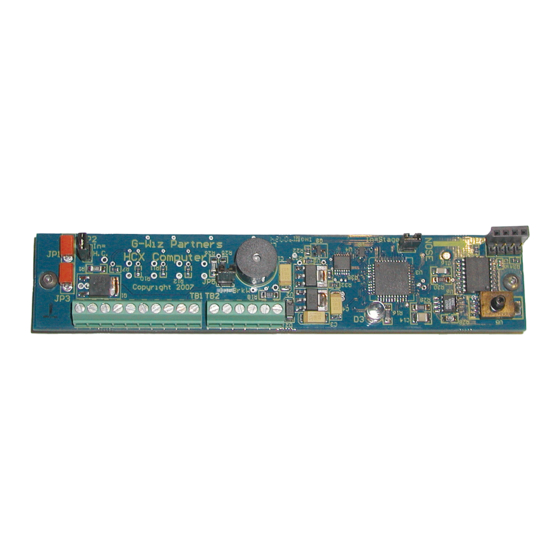
First Flight Version 1.0 Date Printed: 1/26/2008 Components Here are the major components of the G-Wiz HCX flight computer. More information on each of HCX User Manual these components is in the Using your Flight Computer chapter of the • CPU – The RISC processor that controls the Flight Computer. -
Page 8: Product Features
First Flight Version 1.0 Printed: 1/26/2008 Product Features Here are some of the great features you’ll find in your new G-Wiz HCX state-of-the-art flight G-Wiz HCX computer. For more detailed information on using these features, please see the User Manual Robust Hardware •... - Page 9 Data Storage • The firmware is stored in flash memory, and can be conveniently upgraded by the user when new versions are released by G-Wiz Partners. • The flight computer’s configuration is stored in non-volatile EEPROM. • The flight computer records its data on a removable Mini-SD memory card.
- Page 10 First Flight Version 1.0 Printed: 1/26/2008 Safety • An on-board safety shunt prevents arming of HCX pyro ports while you are transporting or working on your rocket. It is designed to be quickly and easily removed once the rocket is on the pad and ready for launch •...
-
Page 11: Flying Your Hcx Flight Computer
Flying your HCX Flight Computer The best way to get to know your G-Wiz HCX flight computer is to start using it. This tutorial walkthrough is based on using it in its simplest mode: as an altimeter in the default G-Wiz configuration. -
Page 12: To Set Up The On-Board Hardware
2. Insert a FAT or FAT32-formatted Mini-SD card into the socket on the bottom side of the flight computer. o For more information on formatting your Mini-SD card see Formatting Mini-SD cards for use in your G-Wiz HCX in the Using your Flight Computer section of the User Manual 3. -
Page 13: To Test The Setup
First Flight Version 1.0 Date Printed: 1/26/2008 To Test the Setup Power your flight computer on. Watch the LED and listen to the Flight Computer Status beep code. The correct sequence is: 1. LED turns on then off. 2. The LED turns on and the beeper gives one (JP7 OUT) or two (JP7 IN) low pitch beeps. 3. -
Page 14: Mounting The Flight Computer In Your Rocket
Printed: 1/26/2008 Mounting the Flight Computer in your Rocket Rigidly Attach the G-Wiz HCX Flight Computer to your Rocket. You must install your flight computer so that it is rigidly attached to your rocket. If the flight computer is allowed to move freely around in a payload bay, it will not accurately record the flight and will report significant errors in the recorded flight data. - Page 15 This photograph shows a top and bottom view of the G-Wiz HCX installed in a Nova Payloader rocket. Please note that the shunt plug is nearer to the aft end of the rocket.
-
Page 16: Getting Ready For Launch
First Flight Version 1.0 Printed: 1/26/2008 Getting Ready for Launch Once your flight computer is set up and the rocket is prepared, then you need to put them both together. Because we are not using the HCX flight computer to control ejection on this flight, make sure to include motor ejection on your flight plan. -
Page 17: Recovering Your Rocket
First Flight Version 1.0 Date Printed: 1/26/2008 Recovering your Rocket As soon as your flight computer detects landing, it will start to read out its maximum altitude. The numbers are beeped out in quick sequences with very brief pauses between each number sequence. Zero is a long beep. -
Page 18: Analyzing Your Flight Data With The Flightview Program
To Read the Data from your Mini-SD Card 1. Make sure the G-Wiz Flight Viewer program, FlightView, is installed on your computer. 2. Put the Mini-SD card into its SD card adapter. 3. Plug the card into an SD reader attached to your computer. - Page 19 First Flight Version 1.0 Date Printed: 1/26/2008 flew. Unless you have powered your flight computer on since flying it, the highest number contains your file. 7. Select the file name and click the Open button to open the flight file. 8.
-
Page 20: To Save The Flight Data To Your Personal Computer
To Save the Flight Data to your Personal Computer 1. Click the Save Document as button on the FlightView main menu bar or select G-Wiz > from the main menu. Save As 2. Navigate to the directory where you plan to store your flight data. -
Page 21: Conclusion
. It is available for download at the G-Wiz web site, http://www.gwiz-partners.com/Downloads/html/docs.html. In that manual you will find detailed information on using the advanced features of the G-Wiz HCX flight computer. This includes detailed information and troubleshooting information for connecting your flight computer directly to your laptop computer. It also includes detailed information on the hardware features of this flight computer. -
Page 22: Using The G-Wiz Flight Computer For More Advanced Flights
But, we know Rocketeers. This next section briefly describes the steps to set up the G-Wiz HCX for more complex flight plans. Where you might have any problems, we have tried to point you to... -
Page 23: Using Flightview To Change The Configuration Of Your Hcx
8 pin Communication Interface socket (JP6) at the nose end of your HCX flight computer. The interface card is available from your retailer in either USB or RS232 formats. If you have used other G-Wiz flight computers, it is the same interface card used for the LCX and MC2 flight computers. -
Page 24: To Connect Your Flight Computer To Your Personal Computer
3. Connect your G-Wiz Interface Card and its data cable to your personal computer. o If you are using the G-Wiz USB interface, your personal computer will start to install the drivers as soon as you connect the card to your computer. - Page 25 First Flight Version 1.0 Date Printed: 1/26/2008 2. Change the configuration on both the and the tabs to match your flight plan. Main Outputs 3. Press when you are done. Upload & Exit 4. Disconnect the flight computer from FlightView. 5.
-
Page 26: Cookbook For Launch Setups
First Flight Version 1.0 Printed: 1/26/2008 Cookbook for Launch Setups This section contains step-by-step instructions for five commonly flown flight plans. Important: All of these setups use a shunt plug to safe the pyro ports during setup and transportation. If your application does not allow you to use the shunt plug or the external shunt, you must test the unit by powering it on. - Page 27 First Flight Version 1.0 Date Printed: 1/26/2008 Jumper and Terminal Blocks Pin Assignments Use these charts as guides for wiring batteries, ejection charges, and igniters Jumper Modes Jumper Position Number With Jumper IN With Jumper OUT JP 2 -- Pyro current selection System allows High Current –...
-
Page 28: Dual Parachute Deployment Using One Nine Volt Battery
First Flight Version 1.0 Printed: 1/26/2008 Dual Parachute Deployment Using One Nine Volt Battery This setup has no clustering or staging - A single battery powers both the computer and firing devices. To Set Up the On-Board Hardware 1. Install a shunt plug into the safety shunt JP1/3. 2. - Page 29 First Flight Version 1.0 Date Printed: 1/26/2008 2. Connect the power source to the CBatt terminals (TB2 Pins 5/6) making sure the polarity is correct and that the shunt plug is in place To Test the Setup After all the devices are hooked up, you can test the system. Make sure the shunt plug is correctly installed and then power the HCX on.
-
Page 30: Dual Parachute Deployment Using Two Batteries
First Flight Version 1.0 Printed: 1/26/2008 Dual Parachute Deployment using Two Batteries This setup has no clustering or staging. One battery powers the computer and the other powers the pyro ports. To Set Up the On-Board Hardware 1. Install a shunt plug into the safety shunt JP1/3. 2. - Page 31 First Flight Version 1.0 Date Printed: 1/26/2008 2. Wire a second battery, in the 9 to 15 volts range, for the pyro ports. Attach it to the PBatt terminals (TB1 pins 1/2) making sure your polarity is correct. Important: DO NOT put a jumper wire from the positive computer battery terminal (CBatt+) (TB2 pin6) to the positive pyro battery terminal (PBatt+) (TB1 pin1).
-
Page 32: Two Stages Plus Dual Parachute Deployment Using Two Batteries
First Flight Version 1.0 Printed: 1/26/2008 Two Stages plus Dual Parachute Deployment using Two Batteries One battery powers the computer and the other one provides power for the pyro ports. The Cluster/Stage pyro port fires one or several motors after the booster burns out. To Set Up the On-Board Hardware 1. - Page 33 First Flight Version 1.0 Date Printed: 1/26/2008 To Wire Up Your Power Connection 1. Wire a battery for the computer to the CBatt terminals (TB2 pins 5/6) making sure your polarity is correct 2. Wire a second battery, in the 9 to 15 volts range, for the pyro ports. Attach it to the PBatt terminals (TB1 pin 1/2) making sure your polarity is correct.
-
Page 34: Single Parachute Deployment At Apogee With A Single Nine Volt Battery
First Flight Version 1.0 Printed: 1/26/2008 Single Parachute Deployment at Apogee with a Single Nine Volt Battery This setup has no clustering or staging - A single battery powers both the computer and firing devices. To Set Up the On-Board Hardware 1. - Page 35 First Flight Version 1.0 Date Printed: 1/26/2008 To Test the Setup After all the devices are hooked up, you can test the system. Make sure the shunt plug is correctly installed and then power the HCX on. The beeper will: 1.
-
Page 36: Cluster Ignition, Single Parachute Deployment At Apogee Using Two Batteries
First Flight Version 1.0 Printed: 1/26/2008 Cluster Ignition, Single Parachute Deployment at Apogee Using Two Batteries One battery powers the computer and the other powers the Pyro Ports. In the Cluster mode the unit fires the cluster motor (or motors) as soon as it detects and confirms launch. - Page 37 First Flight Version 1.0 Date Printed: 1/26/2008 5. Emit two beeps. – Nothing is connected to the Programmable terminals. 6. Then it will pause and cycle the beep pattern again. If this is not the pattern you hear, refer to Appendix B for a list of the Flight Computer Status codes.
-
Page 38: Appendix A - Product Specifications
Flights over 25,000 feet MSL require HCX to be coated with a special epoxy layer. The coating protects the circuit board and components from condensing moisture. This also insures proper electrical operation of HCX. Please contact G-Wiz Partners for special order options. -
Page 39: Appendix B - Flight Computer Status Codes
First Flight Version 1.0 Date Printed: 1/26/2008 Appendix B – Flight Computer Status Codes These status codes are listed by how frequently they are heard. The Normal sequence is listed first and then the error code sequences, 1) low battery, 2) unplugged SD card, 3) breakwire error and 4) power-on self-test failure. -
Page 40: Fatal Error Status Codes
First Flight Version 1.0 Printed: 1/26/2008 Fatal Error Status Codes Break Wire Error The unit is configured for a breakwire launch but the break wire is not connected. 1. Short warble. 2. A 1 second pause, and then the sequence repeats. Warning: If you hear this sequence, you will not be able fly your rocket until the error is corrected. -
Page 41: Post Failure Code Lookup Charts
SD card directory error. Try a different card. Unless the failure is due to a SD card problem that can be remedied by changing cards, POST failures should be reported to G-Wiz support (support@gwiz-partners.com). You should not fly the flight computer. Page 37... -
Page 42: Appendix C - Mechanical Drawing
First Flight Version 1.0 Printed: 1/26/2008 Appendix C – Mechanical Drawing When you design your flight computer’s mounting system, here are the important dimensions you need to know. Page 38... -
Page 43: Appendix D -Installing Usb Drivers On Macintosh
First Flight Version 1.0 Date Printed: 1/26/2008 Appendix D –Installing USB Drivers on Macintosh Installing the USB drivers on the Mac is a bit complex. First, make sure you have FlightView 2.8 or later. If not, download the most recent version from our web-site at www.gwiz-partners.com. -
Page 44: Appendix F - Installing Usb Drivers On Windows Xp
First Flight Version 1.0 Printed: 1/26/2008 Appendix F – Installing USB Drivers on Windows Windows XP seems to be harder for people to install our drivers on, so here is a guided tour. 1. Log into your PC as an administrator before connecting the interface card for the first time. 2. - Page 45 Continue Anyway 10. Repeat steps 1 through 8 for the second driver. Your computer is now ready to connect from FlightView to your G-Wiz HCX flight computer through the G-Wiz USB Interface Card. Page 41...
-
Page 46: Appendix F - Installing Usb Drivers On Windows Vista
First Flight Version 1.0 Printed: 1/26/2008 Appendix F – Installing USB Drivers on Windows Vista Windows Vista is even less straightforward than XP for installing our drivers. Mainly this is because Microsoft is trying to make the process totally invisible to the user. Therefore, if you have anything unusual about an installation, Windows gets confused. - Page 47 First Flight Version 1.0 Date Printed: 1/26/2008 o Windows will start by looking for drivers in Windows Update. There is no way to tell it not to do so. If you click on the Device Installation icon in the notification area of the taskbar you will see this progress window.
- Page 48 First Flight Version 1.0 Printed: 1/26/2008 5. Click I don’t have the disc. Show me other options o Windows will now display: 6. Click Browse my computer for driver software (advanced) o Windows will now open a file browser dialog box: 7.
- Page 49 10. Click Install this Driver Anyway o When Windows tells you it has finished installing the drivers for the G-Wiz USB Interface Card, it will then tell you it has found a second device that needs a driver. Page 45...
- Page 50 Printed: 1/26/2008 11. Repeat this process for the second driver. Your computer is now ready to connect to your G-Wiz HCX flight computer through FlightView. If, after reading this manual, you have any questions or problems with either your flight computer or the FlightView software, please visit us on the web at: http://www.gwiz-partners.com.
Need help?
Do you have a question about the HCX-50G and is the answer not in the manual?
Questions and answers