Table of Contents
Advertisement
Quick Links
Advertisement
Table of Contents

Summary of Contents for RespiWin 520
- Page 1 RespiWin 520 Ventilator User Manual P a g e...
-
Page 2: Table Of Contents
Table of Contents Introduction..............................4 Operation Instruction ..........................4 Know Your Unit ............................4 Main Unit:............................. 4 Accessories ............................6 ................................. Installation ..............................8 Powering on the Device ..........................9 Calibration Process ............................9 Registering a patient ...........................10 Ventilator Settings ............................12 Alarm Setting ..............................13 Waveforms.............................. - Page 3 Standard Warranty ..........................24 P a g e...
-
Page 4: Introduction
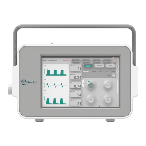
Introduction RespiWin 520 life support versatile ventilator is designed for use in hospitals and in transit, offering invasive and non-invasive ventilation and respiratory monitoring support. Built with a turbine-driven ventilation system to showcase high standards of ventilation therapy in any challenging environment or acute situation. From initial setup to everyday use, RespiWin is an advanced, high quality ICU &... - Page 5 input Flow Input (Negative) Exhale Inhale Flow Input (Positive) DC Input Inhale Port Exhale Port P a g e...
-
Page 6: Accessories
Accessories Patient Circuit Valve Connector Flow Sensor Test Lung P a g e... - Page 7 Hepa Filter Valve Connectors 2 Way Manifold Power Supply P a g e...
-
Page 8: Installation
Installation 1.Let’s begin, while connecting 2 Connectors to the Inhale and Exhale Ports given on the left side of the machine. Connector with the hole is the Expiratory Connector and without hole is the Inspiratory Connector, so connect accordingly. 2. Now join 2 Valves with the Connector. 3. -
Page 9: Powering On The Device
Powering on the Device 1. Switch on the Ventilator and the Tablet. To start the software, Click on the software icon on the screen. Calibration Process 1. To calibrate the Ventilator, at the central right side on the screen, click on the “Calibration and Test button and not on the Upload button. -
Page 10: Registering A Patient
Registering a patient 1. To register a patient, at the top left side of the screen, click on “Patient Name” option. 2. This option will take you to the page as shown in the below image. 3. Start filling up the patient details. 10 | P a g e... - Page 11 4. At the bottom right side on the screen, click on the “add” button as shown in the above image. 11 | P a g e...
-
Page 12: Ventilator Settings
Ventilator Settings 5. To start with the ventilator settings, at the central right side of the screen, click on the “Ventilator Settings”. 6. Click on the specific mode to change the parameters. 7. To set the parameter, long press on the particular knob. 8. -
Page 13: Alarm Setting
9. To start the process, click on the “Upload” button as shown in the below image. Alarm Setting 1. To set the alarm, at the central right side on the screen, click on the “Alarm” option as shown in the below image. 2. - Page 14 Roll the Knob and press ok to confirm. 4. To set the lower value, click on the lower mentioned value as shown in the image. 14 | P a g e...
- Page 15 Roll the Knob and press ok to confirm. 6. To process the command, click on the “Upload” button as shown in the below image. This alarm will sound if the ventilator exceeds or drops below certain limits. 15 | P a g e...
-
Page 16: Waveforms
Waveforms 1. To have a complete view of the graph, click on central button on the screen as shown in the image below. 16 | P a g e... -
Page 17: Technical Data
Technical Data 17 | P a g e... - Page 18 18 | P a g e...
-
Page 19: Modes
Modes Pressure Control Ventilation Modes PCV (Pressure Control Ventilation) Pressure Control Ventilation (PCV), In this mode, the peak airway pressure is constant (inspiratory pressure + PEEP) while the tidal volume can be variable depending on patient characteristics (compliance, airway/tubing resistance) and driving pressures. PACV (Pressure Assist Control Ventilation) Pressure assist-control ventilation (PACV) is a Pressure targeted time-cycled ventilator support mode in which a nearly constant pressure is applied to the airways opening, in this pressure cycled... -
Page 20: Volume Control Ventilation Modes
The ventilator detects the patient’s spontaneous breathing, and waits until the patient exhales before delivering another mechanical breath. This "synchronizes" the ventilator to the spontaneous breathing. All spontaneous as well as mandatory breaths will be pressure control breaths. A patient on an SIMV of 12 with a total breathing rate of 20 breaths per minute is receiving 12 breaths from the ventilator and taking 8 spontaneous breaths. -
Page 21: Bipap S/T (Bi-Level Positive Airway Pressure)
BIPAP S/T (Bi-level Positive Airway Pressure) The S/T or Spontaneous/Timed mode offers a combination of machine delivered breaths (set respiratory rate) and spontaneous (patient triggered) assisted breaths. BIPAP S (Bi-level Positive Airway Pressure) The S or Spontaneous mode offers support to the breaths the patient takes on his/her own. 21 | P a g e... -
Page 22: Warning Cautions
Warning Cautions Read the entire manual before using the RespiWin 520 Install and configure the RespiWin 520 in accordance with the instructions provided in this guide. Do not calibrate the ventilator when it is connected to the patient, instead calibrate using test lung given along with the machine. -
Page 23: Maintenance
Maintenance The cleaning and maintenance described in this section should be carried out regularly. Refer to the user guides for the patient interface and other accessories in use for detailed instructions for care and maintenance of those devices. ... - Page 24 Standard Warranty DRC warrants that your DRC’s product shall be free from defects in material and workmanship from the date of purchase. If the product fails under conditions of normal use, DRC will repair or replace, at its option, The defective product or any of its components. One-year Warranty does not cover: a) Any damage caused as a result of improper use, abuse, modification or alteration of the product repairs carried out by any service organization that has not been expressly...
Need help?
Do you have a question about the 520 and is the answer not in the manual?
Questions and answers