Table of Contents
Advertisement
Advertisement
Table of Contents

Summary of Contents for Topotek TGIP10A
- Page 1 TGIP10A 10x IP Gimbal User Manual V1.02 2020.06.08Revision...
-
Page 2: Table Of Contents
Contents Warning and Disclaimer ..........................2 1. Product Introduction ............................. 3 2. Product List ..............................3 3. Mounting & Configuration ..........................3 3.1 Gimbal installation attention ......................3 3.2 Gimbal structure description ......................5 4.Telecom ................................ 7 4.1Serial Port Communication ........................7 4.2 UAV remoter control ........................... -
Page 3: Warning And Disclaimer
TOP- TGIP10A is a delicate instrument.Do not disassemble the gimbal or camera as this will cause permanent damage. In order to ensure the safety of flight control system after powering up, we recommend you to remove all the propellers and use non -power-supply for the gimbal. -
Page 4: Product Introduction
1. Product Introduction TGIP10A, a great 3-axis gimbal for model aircraft enthusiasts, It provides a 10×optical zoom.The 1/3 CMOS sensor supports approx.4 million effective pixels. With unique internal wiring design, built-in IMU gimbal control module, specialized servo drive module, Network IP output mode. - Page 5 powered on.check the picture is normal display and confirmed the gimbal normal working。 ②.When connect the HD transmission equipment,pls Do not leave both on the same level, to avoid interference with the equipment. At the same time check whether the connection line is stable。...
-
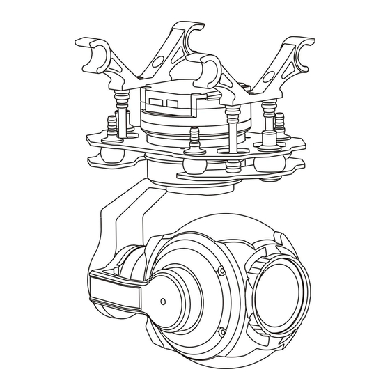
Page 6: Gimbal Structure Description
3.2 Gimbal structure description Number Corresponding YAW Motor Roll Motor Tilt Motor Camera Product Interface: @2019topotek All Rights Reserved. - Page 7 1. Use serial port commands to control gimbal 2. Use PWM/SBUS to control gimbal Power Power supply:11V-26V (3S-6S Li batter y) 1: S.Bus control mode Take the s.bus lead in [network and SBUs control line], 5V power output and GND line to form 3P s.bus signal output line GND:Signal Ground 5V OUT:5V voltage output...
-
Page 8: 4.Telecom
inside the card. Gimbal Customer can debug the Gimbal through the Micro-USB port. debug Electrical Interface Type/Definition/Function Seq. Pin Type Interface Type Definition Function Power Interface Power Interface 3S-6S DC input Control interface Gnd for signal 6PIN Not connect Control interface UART_IN UART IN port Control interface... - Page 9 #tp:Changing length, data length depends on length,maximum length is:0x0F; Target Bit: Source Bit: U: Uart;M: lens related command; D: system and image related command; I: algorithm related command; E: thermal image related command; G: gimbal related command; Data Bit: byte and maximum length F Control Bit: r –...
-
Page 10: Uav Remoter Control
2. Gimbal Speed Control and Camera Control 4.2 UAV remoter control The Gimbal can be controlled through the S.Bus port or Multi PWM channel. And each channel control a function. ① Gimbal Pitch Select a Rotary button switch or Rocker or 3 position switch: Example the default THR channel 3: Rocker upside: look up;... - Page 11 Rocker in middle position: no operation; Rocker downside: look down The setting with the rocker up and down corresponding to the pitching direction of the platform can be adjusted. ② Gimbal Yaw Select a Rotary button switch or Rocker or 3 position switch: Example the default RUD channel 1: Rocker left: Gimbal turn left;...
- Page 12 Rocker in middle position: no operation; Rocker right : Focus near The setting with the rocker left and right corresponding to the camera focus can be adjusted. ⑤ Capture and Record Select a Rotary button switch or 3 position switch Example 3 position switch:...
-
Page 13: Specifications
5. Specifications Product parameters Name TGIP10A Input Power 3S-6S Li (11V-26V) Working Current 250ma Working Environment -20℃~+50℃ Weight 365g Max Controllable Rotation Speed 77 mm *105 mm *147mm TILT:-120 deg~ +15deg Controllable Rotation Range Pan:-125 deg~ +125 deg Attitude Control Accuracy ±0.02deg... - Page 14 If the product version needs to be upgraded or the functions are required to be changed, please feel free to contact us for further technical support. Name: Jianlong Cai Mailbox: caijianlong@topotek.com Contact: (+86) 13331001415 Hangzhou Topotek Vision Technology Co., Ltd. R&D Center(Hangzhou): Room 1001, Building A, Hangzhou artificial intelligence Industrial @2019topotek All Rights Reserved.
- Page 15 R&D Center(Beijing): Room 909, Unit 1, Building N.O. 3, Zhujiang Moer International, Beiqing Road 1, Changping District, Beijing, China. Product Center(Shenzheng):Room 911, Shangmei Chuangke Building, Huanguan Nan Road, Longhua District, Shenzheng, China. Official Website:http://www.topotek.com Version V1.02 @2019topotek All Rights Reserved.
Need help?
Do you have a question about the TGIP10A and is the answer not in the manual?
Questions and answers