
Summary of Contents for Vcheck V2400
- Page 1 FOR VETERINARY USE ONLY USER MANUAL V2400 FLUORESCENT IMMUNOASSAY SYSTEMS FLUORESCENT IMMUNOASSAY SYSTEMS...
- Page 2 VC7403EA Doc. No.: I7403-2E Issued date : Apr. 28, 2020 Thank you for your purchase of the BIONOTE V2400 Than yo your chas IONO NOTE This User manual contains all information about the Analyzer. Please read this User Manufactured by...
-
Page 3: Table Of Contents
..................15 Protection from Infection ..............57 Appearance of BIONOTE V2400 Analyzer ..........16 Electromagnetic compatibility .............. 57 Included of the BIONOTE V2400 Analyzer ..........18 Disposal ....................57 Warranty ....................57 Chapter 03. Log On and Setting Operation of Analyzer ................19 Chapter 04. -
Page 4: Chapter 01. General Information
Chapter 01. General Information Work Place Calibration Utility Test Result Test QC Result Monthly Work Place Run QC System Maintenance Statistics Operator Network Status Review Calibration Status Review review QC with Start Prepare External Date Control Network (Input Operator CAL Device /Time solution Insert... -
Page 5: Main Menu Structure
Main Menu Structure Abbreviations Symbols and Abbreviation Abbreviation Description Comm Communication The symbols and abbreviation presented below are indicated on the User Manual, Laboratory Information System labels and external package. Hospital Information System Symbols Graphic User Interface Symbols Description Software Firmware Manufacturer In Vitro diagnostic use... -
Page 6: Precautions
Precautions To reduce the risk of biological hazards Discard the used specimens in accordance with federal, state and local requirements. To reduce the risk of damage to Analyzer Biohazard! Treat specimens as potentially biohazardous material. Use the Analyzer for in vitro diagnostics only. If you have no experience with collection and handling of Caution specimens, appropriate education or guidance should be... -
Page 7: Chapter 02. Overview
Product overview The BIONOTE V2400 Analyzer scans the 2D barcode of inserted test device. Based on the scanned result of the inserted test device, the analyzer determines the appropriate LED (UV, RGB) settings for the test device. - Page 8 Specimens The BIONOTE V2400 Analyzer should be only used the specific test devices for the analyzer. Because specimens are quite different for each parameter, follow the AC 100~240V, 50/60Hz Input Voltage instructions from the each test device instructions. 10.1” Color TFT LCD (1024 X 600)
-
Page 9: Appearance Of Bionote V2400 Analyzer
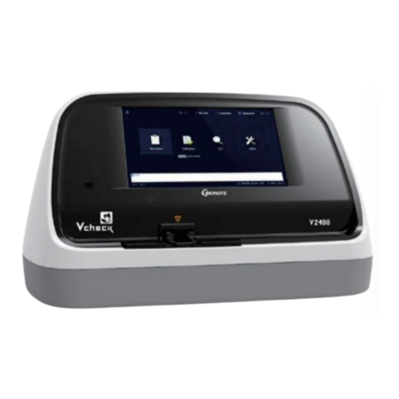
Appearance of BIONOTE V2400 Analyzer A. Color TFT LCD Used for test screen display and interaction with graphical user interface B. Inlet for insertion of test device Used for insertion of test device into the Analyzer C. Test device outlet Used for discharge of test device that has completed the test D. -
Page 10: Included Of The Bionote V2400 Analyzer
Included of the BIONOTE V2400 Analyzer Chapter 3. Log On and Setting Operation of Analyzer Step 1. Connecting the power cable 1-1. Place the Analyzer in a proper environment where it can be plugged into outlet and barcode scanner (optional) can be positioned together. - Page 11 Brightness/Volume and proceed with the update. How to update the software iii. b. Connect the USB(that V2400 Software is copied) to the USB port on the bottom left of the V2400 Analyzer. c. If the USB is connected normally, “USB connected successfully” will be displayed.
- Page 12 When the button is enabled, click the button. F/W Update Items needed for F/W update · BIONOTE V2400 Analyzer · · Mini-5pin USB cable · Personal computer (Not provided) How to update the F/W a. Connect your PC and device with a Mini USB cable. If the driver is not recognized on PC, install the CP2101 driver.
- Page 13 Due Date Area: You can set the period of test items. Press button to Event Log Date & Time Area: Date and time of event log are displayed. Event Log Area: History of all items tested by V2400 Analyzer is displayed in chronological order. 5) Brightness/Volume setting Log Clear Button: Delete the selected event log.
- Page 14 Statistics Menu Operator Menu 1) On the Statistics tab, you can check the number of tests, calibration, and QC 1) An Operator item can be registered, edited, and deleted. tests for each item. · Password in Operator is the same as the password used for log-on. The number of times that each test has been performed is displayed.
- Page 15 · To modify the Operator ID, select the ID, press “Edit”, type ID you wish to · To delete the Operator ID, select the ID, select the ID, press “Delete”, then modify, and then press “OK” press “ OK” Network Menu 1) On the Network tab, you can set the HIS/LIS and Analyzer network.
-
Page 16: Chapter 04. Work Place
Chapter 4. Work Place 1) Run test Menu “Run test” is a mode for testing the samples from patients. After entering patient information in “Patient ID”, press to move to Performing a Test & Reviewing data the next step. Patient ID can be entered by using the touch keyboard. You can also enter Patient ID by using a barcode scanner or by an external keyboard connected Before proceeding a test, check the following : by USB. - Page 17 Analyzer checks the conditions of the inserted test device. If the test device has already been used, E-1 error pops up. When the sample checking is completed, the test device is mounted inside the Analyzer. samples should be prepared according to the instruction for each test and applied to the sample well of the test device.
- Page 18 2) Test Status Menu If you select a completed item, you can check details of the test(Test Result, “Test Status” menu shows the progress of test in the Analyzer. Name Label, Procedural Control, Test Date and Time, Operator ID, Patient ID, Manufacturing Date of the test deivce, Software Version).
- Page 19 Select from the drop-down list on the right. And select a For quantitative test, you can change the measurement unit by pressing the test from list shown in [Area A]. All of the test results belonging to the item under “Units” in the list on the right side[Area B]. (Available only when selected Patient ID will be shown in [Area B].
-
Page 20: Chapter 05. Calibration
Chapter 05. Calibration Insert the Cal-1 Device into the test slot of the Analyzer. Calibration Set Test Calibration Set Test is an essential function that ensures optimal performance of the Time for use of Calibration Set Whenever the Analyzer is turned on When Analyzer is dropped When the result does not match the desired result When you want to check the performance of the Analyzer and test device... - Page 21 After inserting all the calibration devices, the analyzers performs the 2. Calibration Review Menu calibration analysis. The result of calibration can be checked in “Calibration Review”. When the analysis is completed, you can check the result screen. You can check the details by selecting the Result from the list. ·...
-
Page 22: Chapter 06. Quality Control
Chapter 6. Quality Control Select a list and press “Delete Record”( ) to clear the selected items. Press the “Delete All”( ) to clear all results. Quality Control Test To verify whether the Analyzer’s system is functioning properly and whether the test procedure is correct, perform QC with one or more levels of quality control materials. - Page 23 1) QC with Control solution The Analyzer checks the conditions of inserted test device. If the test device has already been used, an E-1 error pops up. Select “QC with Control solution” and the next screen will be shown. Enter the information of quality control material (barcode number) and press OK to proceed to the next step.
- Page 24 After the check is completed, the test device is mounted inside the Analyzer. Analyzer checks the conditions of inserted test device. If the test device has already been used, an E-1 error pops up. Once the mounting is complete, you can start a test procedure. control material appears.
- Page 25 · Example of Quantitative test Once the verification is completed, the test device is mounted inside the Analyzer. After applying the prepared quality control material, press “QC Start” immediately. 3) QC Result review Menu You can check the result of QC in “QC Result review”. a.
- Page 26 Example) The results obtained when result retrieval period is set to 4) Monthly Review Menu 2018.01.01-2019.02.11 and then cPL is selected from the drop-down list In ”Monthly Review”, you can check the monthly value of quantitative test. If you select the period and press “Table”, the QC results for that period are provided in the form of a list.
-
Page 27: Chapter 07. Cleaning & Maintenance
Analyzer. Enter the correct password. Note Warning: No Update File The V2400 Analyzer was designed to meet safety standards. Do not modify or repair the Analyzer. Do not repair the Analyzer yourself without the help of the Solution supplier. -
Page 28: Error Messages
Warning: Incorrect IP address E04: Temperature error Incorrect IP address entered. The ambient temperature deviates from the operating temperature range of the test device. Solution Solution correct IP address. Move the Analyzer and test device into proper temperature range and perform the test. Do not E05: Communication error Communication between Analyzer and barcode or between Analyzer and printer has failed. -
Page 29: Protection From Infection
Waste Electrical Electronic Equipment (WEEE) regulation corresponds to the European Directive 2002/96/EC for reduction of wastes from the Analyzer. Before any disposal of BIONOTE V2400 Analyzer, please Warranty You are a valued customer of BioNote, Inc. It is important to us that you are completely satisfied with the BIONOTE V2400 analyzer. - Page 30 MEMO MEMO...
Need help?
Do you have a question about the V2400 and is the answer not in the manual?
Questions and answers