Table of Contents
Advertisement
Advertisement
Table of Contents

Summary of Contents for Solidscape 3Z Series
- Page 1 series User Manual Part Number 840180 Rev F August 2013...
- Page 2 Base, 3Z Model, 3Z Support are either trademarks or ® registered trademarks of Solidscape , Inc. ® is a registered trademark of Solidscape , Inc. ® BIOACT is a registered trademark of Petroferm, Inc. ® Windows is a registered trademark of Microsoft Corporation in the United States and/or other Countries.
- Page 3 Class A Digital Device This equipment has been tested and found to comply with the limits for a class A digital device, pursuant to Part 15 of the FCC Rules. These limits are designed to provide reasonable protection against harmful interference when the equipment is operated in a commercial environment.
-
Page 4: Limited Warranty Statement
Limited Warranty Statement 3Z Series Solidscape, Inc. warrants this 3Z Series System to be in good working order for a period of one year from the date of installation and registration. Should this Product exhibit any manufacturing defects during the warranty period, Solidscape or its authorized agent will, at its option, replace, repair or provide replacement parts for this Product at no additional charge except as set forth below. -
Page 6: Table Of Contents
Table of Contents SERIES ..........................III LIMITED WARRANTY STATEMENT ................... V 3Z SERIES ............................ V TABLE OF CONTENTS ......................VII LIST OF FIGURES ........................IX CAUTIONS ..........................XI CHAPTER 1 - SYSTEM OVERVIEW ................... 1 LED S ....................2 TATUS NDICATORS ........................ - Page 7 ..................29 LEANING THE AMERA .............. 29 LEANING THE URGE EMOVAL TATION MDS S ............. 31 LEANING THE ENSOR AND URGE ..............32 LEANING THE APER SSEMBLY CHAPTER 8 – PRINTER SUBORDINATE SYSTEMS .............. 33 ................33 TATUS CREENS VERVIEW ....................
-
Page 8: List Of Figures
Figure 10-3 Wireless MAC Address .................... 44 Figure 10-4 Wireless Ethernet Adapter ..................44 Figure 10-5 Stylus and Touch Screen ..................45 Figure 10-6 3Z Series Printer Control Panel ................46 Figure 10-7 DM9CE1 Icon ......................46 List of Figures... - Page 9 Figure 10-8 Entering the IP Address ..................47 Figure 10-9 Starting Windows 7 Control Panel ................48 Figure 10-10 Windows 7 Control Panel ..................49 Figure 10-11 Windows 7 Network and Sharing Center .............. 50 Figure 10-12 Windows 7 Network Connections ................. 50 Figure 10-13 Starting Windows XP Control Panel ..............
-
Page 10: Cautions
Cautions This manual includes several types of special operator notification; general CAUTIONS, temperature related CAUTIONS, flammability related CAUTIONS and Notes. All CAUTIONS are accompanied by an appropriate, internationally recognized symbol and all notifications are enclosed in a bounding box to highlight their significance. CAUTION! General cautions are further distinguished by the accompanying international Caution symbol and are printed in bold face type. - Page 11 AFETY NTERLOCK Always keep the top cover and side panel closed during operation! The system is equipped with a safety interlock that suspends and prohibits potentially hazardous model making operations when the cover or side panel are opened. ...
- Page 12 Store unopened materials in their original containers in a cool, dry place and out of direct sunlight. CAUTION! The use of any materials other than new materials provided by Solidscape voids the system warranty. OWER ORDS Customers, in locations other than the USA, may need to install or replace the plug of the following cords with one compatible with their electrical outlets.
- Page 13 Cautions...
-
Page 14: Chapter 1 - System Overview
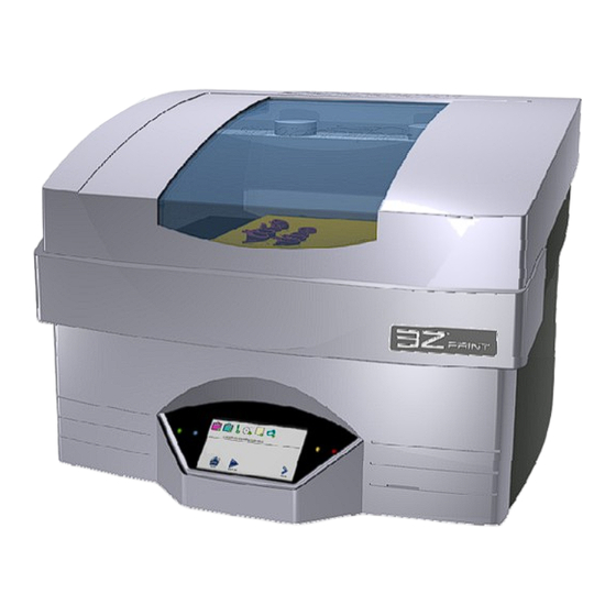
Chapter 1 - System Overview The 3Z Series Model Making System renders high precision, three dimensional (3D) models from CAD model files. The system consists of all the hardware and software necessary to fabricate models and prepare them for final processing. Applications program that resides on the printer provide local control over the model making unit. -
Page 15: Led Status Indicators
LED Status Indicators There are four status indicator lights on the 3Z Series model making system. The two on the left of the touch panel are the Green (Power) indicator and the Blue (Busy) indicator. The two on the right of the control panel are the Yellow (Caution) and Red (Intervention) indicators. The indicators can be off, blinking, or steady on. -
Page 16: Figure 1-4 3Z Touch Panel
functions. Randomly selecting these functions without understanding what they do, could render the system inoperable until these settings are correctly restored! The touch panel is divided into 2 sections Status and Command. See Figure 1-4.The icons above the black line indicate the status of user responsible consumables, the job progress Indicator bar and the printer Ready/Status indicator. - Page 17 detailed information and operational control. The corresponding Ready/Status indicators are shown to the right. There is no Ready/Status indicator for Idle. The 8 basic scenarios are: 1. Initialization - The printer is initializing and resetting hardware and software components during a reset, power up, or recovery. 2.
-
Page 18: Organizer - 3Z Print - 3Z Works - 3Z Analyzer
Details regarding the installation and operation of the 3Z Works, 3Z Analyzer, 3Z Print and 3Z Organizer programs are provided in the 3Z Works User’s Manual, P/N 840202, which is available on the Solidscape 3Z Series Software Flash Drive, P/N 945087... - Page 19 3Z Analyzer 3Z Analyzer is a Windows application program that runs on the operator’s workstation. It permits job file viewing, analysis and correction of the job file for pre-build evaluation, repair and diagnostic purposes. It also allows the operator to view the job file one ‘slice’ at a time exactly as it will be printed on the system.
-
Page 20: Chapter 2 - Power On Procedure
Step 4 through Step 7 of this procedure must also be performed after the vacuum filter has been replaced. All references to the ‘unit’ refer to the actual 3Z Series printer. 1. Confirm that the unit is powered off by pressing the ‘0’, side of the power switch on the left rear corner of the unit. -
Page 21: Figure 2-1 Initialization Screen
Both covers must be closed or the interlock will prevent the system from completing the start up sequence. 3. Turn on the 3Z Series system by pressing the ‘I’, side of the power switch on the left rear corner of the unit. -
Page 22: Figure 2-2 Initialization Screen With Camera Issue
Figure 2-2 Initialization screen with Camera issue 6. If the system was shut down or lost power while a job was active, a temporary dialog box will be displayed that disables all other operations during the twenty minute system warm up period. - Page 23 Power on Procedure...
-
Page 24: Chapter 3 - New Job Startup
Chapter 3 – New Job Startup Before a new job can be printed, the 3Z Base or (Build Plate) must be mounted on the printer and a job file must be loaded. Figure 3-1 shows that there is a red X next to the 3Z Base icon and also next to the job file icon indicating that these processes must be completed before a job can be started. -
Page 25: Build Plate Mounting
Figure 3-2 Build Plate Build Plate Mounting 3.1.1 1. Ensure that the back, metal surface of the build plate is smooth and clean and free from material and debris. 2. Ensure that the build plate mounting hole and slot are clean, unobstructed and free from material and debris. -
Page 26: Build Plate Barcode
Figure 3-3 Build Plate Mounting Build Plate Barcode 3.1.2 Each build plate has as unique barcode attached to the metal surface. The printer uses this barcode to automatically identify and position the build plate for each print job. The barcode is read by the camera and then the printer processes the information. -
Page 27: Cleaning The Cutter
Cleaning the Cutter CAUTION! Mechanical Hazard. Use extreme caution when working in the vicinity of the cutter blade. 1. After each layer of the model is printed, the cutter blade trims the build and support material to the exact height specified by the print job parameters. The blade is extremely sharp. Do not touch the cutter blade. -
Page 28: File Transfer And Removal
A job file must be transferred to the printer every time a new print job is run. The file type for the 3Z Series printers must have an extension of .3zp. for the 3Z Pro, 3zm for the 3Z Max and .3zs for a 3Z Studio. -
Page 29: Removing A File
Printer driver, select the PRINT button. Refer to the 3ZWorks User’s Manual, P/N 840202, which is available on the Solidscape 3Z Series Software Flash Drive, P/N 945087. Removing a file. 3.3.3 1. From the System Idle screen select More. 2. Select Clear Job. -
Page 30: Chapter 4 - During Job Run
Chapter 4 – During Job Run During the print job, the progress bar will move from left to right, indicating the progress of the file and estimated completion time. See Figure 4-1 Job Printing Figure 4-1 Job Printing Pausing the Job At any time you can select Pause Job to interrupt the printing by touching the Pause icon. -
Page 31: Figure 4-2 Job Paused
Figure 4-2 Job Paused If you want to terminate the print job, select the Terminate icon At this point the printer will ask you to verify the termination of the print job. Touch Yes to verify or No to return to the pause menu. See Figure 4-3 Terminate Job Figure 4-3 Terminate Job During Job Run... -
Page 32: Chapter 5 - Job Finish
Chapter 5 – Job Finish When the printing job has completed successfully, the Ready / Status indicator will display the Finish flag. See Figure 5-1 Job Waiting for Finalize. Touching the Finalize icon will raise the table, open the cover, and the current job file will be removed from the printer. See Figure 5-2 Job Finalized. - Page 33 Job Finish...
-
Page 34: Chapter 6 - Replacing Consumables
Chapter 6 – Replacing Consumables Paper Tape When the paper tape roll reaches a low level, the status of the paper tape icon will change to a yellow Warning state. At this time the paper tape roll should be changed as soon as possible. If the printer is running, pause the job and open the top and right side covers before proceeding. -
Page 35: Build And Support Materials
The crayons are supplied in a box of 10. The box will also contain 10 peel and stick bar code strips used to verify that the material was manufactured by Solidscape. Note: Every time a crayon is added, a barcode must be scanned into the printer. -
Page 36: Adding Material
Adding Material 6.2.1 To add a crayon, follow the example below. The example is illustrated for the build reservoir. On the system Idle screen, Touch the Reservoir icon. A new information screen will open. Now touch the Add icon. The paper tape will move forward and a rectangle frame will be printed on the paper. The top cover will then open. -
Page 37: Figure 6-4 Entering Barcode Manually
Figure 6-4 Entering Barcode Manually If material is added without entering a barcode, the printer will routinely prompt the user to enter a valid barcode. See Figure 6-5 Barcode Missing. A barcode should be entered as soon as possible. The printer must be Idle and the cover closed to enable a barcode entry. Note: Do Not Add Material to the printer. -
Page 38: Chapter 7 - Maintenance And Printer Status
Chapter 7 – Maintenance and Printer Status Printhead Maintenance The Printhead screens provide status information and control functions required to maintain the printheads. Under normal conditions, the operator does not need to utilize these screens because the basic printhead setup is completed whenever a new job is started. There are 2 dialog boxes associated with printhead maintenance. -
Page 39: Figure 7-1 Printhead Screens
Figure 7-1 Printhead Screens Maintenance and Printer Status... -
Page 40: Automated Printhead Maintenance
Automated Printhead maintenance 7.1.1 The Printhead information screen has one status and 2 command icons. The status icon will indicate when the printhead is functioning properly and ready for a job build. A green check indicates ready and a red X indicates not ready. See Figure 7-2 Printhead Ready / Not Ready. -
Page 41: Figure 7-3 Detailed Printhead Maintenance
Figure 7-3 Detailed Printhead Maintenance and the operating hours. It also allows the operator to perform specific commands and tests on the printhead. See Figure 7-3 Detailed Printhead Maintenance. Any of the printhead commands can be immediately interrupted by touching the Stop icon. See Figure 7-4 Stop Command. Figure 7-4 Stop Command Maintenance and Printer Status... -
Page 42: Cleaning The Camera Lens
Test Touching the test icon will command the printhead to print a single test line or cross on the paper. The camera will then attempt to read the line. If the line is read successfully, the printhead icon will have a green check next to it. If there is a failure, the printhead icon will have either a red x or yellow warning check. -
Page 43: Figure 7-6 Cleaning The Purge Cap Removal Station
the remaining debris removed with a Qtip moistened with Isopropyl alcohol. See Figure 7-6 Cleaning the Purge Cap Removal Station. Figure 7-5 Cleaning Camera Lens Figure 7-6 Cleaning the Purge Cap Removal Station Maintenance and Printer Status... -
Page 44: Cleaning The Mds Sensor And Purge Caps
Cleaning the MDS Sensor and Purge Caps The MDS (Material Deposition Sensor) is used to calibrate and test the printheads. The sensor must be clean and free from debris in order to function properly. The MDS sensor is located to the right of the build plate and is normally covered by the paper tape. -
Page 45: Cleaning The Paper Tape Feed Assembly
Figure 7-8 Cleaning the Purge Cap Cleaning the Paper Tape Feed Assembly. The paper tape feed assembly pulls the paper over the MDS sensor and then ejects the paper out through the front of the printer. It uses a system of gears to advance the paper. These gears should be checked periodically for debris. -
Page 46: Chapter 8 - Printer Subordinate Systems
Chapter 8 – Printer Subordinate Systems Idle / Status Screens Overview There are two Idle / Status screens that allow the user to gather information from, and Initiate commands to, various sub systems within the printer. These sub systems are accessed from the System / Idle screens by touching the More and Back icons. -
Page 47: Subordinate Systems
Subordinate Systems Temperature information 8.2.1 Touching the thermal icon will display the current temperatures of the printheads, heated lines, material reservoirs and the build chamber. Normal operation requires all devices have a green check next to the icon. See Figure 8-2 Temperature Information. -
Page 48: Table
Figure 8-3 Tank Material Information Table 8.2.4 Touching the table icon opens the Table Maintenance dialog box. Touching the individual icons will allow the user to move the table up or down a specific amount, or move the table to the up most position. The user can also perform a foam cut of the 3Z Base. -
Page 49: Job Information
Job Information 8.2.5 Touching the Job Information icon will open the Job Status Information dialog box. The information displayed includes the current number of layers completed, printhead performance and number of calibration tests required to reach the acceptable values. Figure 8-5 Job Information. Figure 8-5 Job Information Standby 8.2.6... -
Page 50: About
About 8.2.7 Touching the About icon will display important printer information. This information is used to verify that the printer has the correct software and firmware revisions installed. See Figure 8-6 About Printer Information. Figure 8-6 About Printer Information 8.2.8 Touching the MDS icon will display the current status of the MDS calibration sensor. - Page 51 Printer Subordinate Systems...
-
Page 52: Chapter 9 - Function Test
Chapter 9 – Function Test Touching the Funct Test icon will open a dialog box that allows the user to operate and verify various sub systems within the printer. Touching the Vacuum icon will toggle the power to the vacuum. Touch once to apply power to the vacuum and touch again to remove power from the vacuum. - Page 53 5 seconds and then automatically deactivate and lower the paper to the normal height. The Net Test button is used for verifying and troubleshooting printer network settings. Please contact the Solidscape service department for further assistance. Function Test...
-
Page 54: Chapter 10 - Connecting The Printer To Your Pc
This is the most common and easiest way to connect your 3Z Series printer to a network. The 3Z Series printer’s ship from the factory with the network default set to use DHCP. You will need a standard Cat5e network cable to make the network connection. See Figure 10-1 Insert one end of the network cable into the network connection port on the rear of the 3Z Series printer. -
Page 55: Wired Connection Via Static Ip Address
3Z Series printer’s ship from the factory set to use DHCP, you will need to configure the 3Z Series printer to use a static IP address. You will need a standard Cat5e network cable and an IP address and subnet mask to use. Your network administrator will provide you with the IP address and subnet mask. -
Page 56: Wireless Via Dhcp
Your 3Z Series printer is now connected to your network. 10.5 Wireless via DHCP To wirelessly connect the 3Z Series printer to your wireless network, you will need a third party wireless Ethernet adapter. The wireless Ethernet adapter must connect to the 3Z Series printer Ethernet port, wireless USB adapters will not work on the 3Z Series printers. -
Page 57: Assigning A Static Ip Address To A 3Z Printer
Once the wireless Ethernet adapter has been configured, plug the wireless Ethernet adapter into the network port on the rear of the 3Z Series printer. Plug in the wireless Ethernet adapters power supply. The wireless Ethernet adapter should connect to your wireless network and supply an IP address to the 3Z Series printer. -
Page 58: Figure 10-5 Stylus And Touch Screen
Figure 10-5 Stylus and Touch Screen Touch the button and select Settings Control Panel. From the Control Panel double click “Network and Dial-Up Connections”. See Figure 10-6. Connecting the Printer... -
Page 59: Figure 10-6 3Z Series Printer Control Panel
Figure 10-6 3Z Series Printer Control Panel Once the “Network and Dial-up Connections” window opens, double click on the “DM9CE1” icon to open the properties windows for the network adapter. Open the status bar again and click the icon and click the icon, this will open the virtual keyboard. -
Page 60: Windows 7 Static Ip Address Assignment
Figure 10-8 Entering the IP Address Click on the button to accept the values and close the settings window. Press the button to close the Network Connections window. Close out any open windows by pressing icon for that window. Power the machine off and back on. -
Page 61: Figure 10-9 Starting Windows 7 Control Panel
Figure 10-9 Starting Windows 7 Control Panel Connecting the Printer... -
Page 62: Figure 10-10 Windows 7 Control Panel
Figure 10-10 Windows 7 Control Panel In the Network and Sharing Center, click the “Change adapter settings” link. This will open the Network Connections window. Connecting the Printer... -
Page 63: Figure 10-11 Windows 7 Network And Sharing Center
Figure 10-11 Windows 7 Network and Sharing Center Figure 10-12 Windows 7 Network Connections In the Network Connections window, right click on the “Local Area Connection” icon and select “Properties”, this will open the “Local Area Connection Properties” window. In the Local Area Connection Properties window, select “Internet Protocol Version 4 (TCP/IPv4)”... -
Page 64: Windows Xp Static Ip Address Assignment
radio button to select “Use the following IP address” and enter 192.168.0.1 for the IP address and 255.255.255.0 for the subnet mask. Click the button to close the Internet Protocol Version 4 (TCP/IPv4) Properties window. Click the button to close the Local Area Connection Properties window. -
Page 65: Figure 10-14 Windows Xp Control Panel
Figure 10-14 Windows XP Control Panel In the Network Connections window, right click on the “Local Area Connection” icon and select “Properties”, this will open the “Local Network Connection Properties” window. In the Local Network Connection Properties window, select “Internet Protocol (TCP/IP)” and click the button. -
Page 66: Figure 10-15 Windows Xp Network Connection Properties
Figure 10-15 Windows XP Network Connection Properties Connecting the Printer... - Page 67 Connecting the Printer...
-
Page 68: Chapter 11 - Post Processing
The following sections describe one method and a CIMERAC brand Heater Stirrer to complete the dewaxing process. It is not the only method .However; it has been tested within the Solidscape facilities and proven successful. -
Page 69: Model Removal From 3Z Base
before the VSO needs to be changed. VSO will saturate with 3Z Support at some point (depending on model geometry or quantity of models) and will have to be changed. Dispose of used VSO in accordance with your local regulations. As a general rule of thumb, the less the model is exposed to heat, the more accurate it will remain. -
Page 70: Dewax - 3Z Support Material Removal
off the 3Z Base and remove the plate from the heater. Typically this process can take between 20 – 30 minutes. 4. Once the 3Z Base plate cools, it is ready for re-use on the unit. Figure 11-2 Heater Stirrer with build plate 11.4 Dewax –... -
Page 71: Post Processing Tool Kit Suggestions
4. Check the model every 15 minutes to evaluate its progress. It may be necessary to adjust the heater control up or down slightly to maintain the bath within the ideal de-waxing range of 50°C - 55°C without exceeding the 55°C maximum bath temperature. It may also be necessary to flip or rotate certain designs to facilitate faster, more efficient de-waxing. - Page 72 c. The model should have the following characteristics (depending on the layer thickness used): Crisp edges, corners and round surfaces. Shiny finish on all surfaces (only thin layer models). Clean finish on all sides (not uneven on verticals). 2.
- Page 73 Post Processing...
-
Page 74: Appendix A - Preventive Maintenance Schedule
Appendix A - Preventive Maintenance Schedule Every Component Required Weekly Monthly Yearly Material Reservoir Levels Check Add Mat'l Verify Calibrate Paper Tape Roll Check Replace Print Head Purge Cup Check Replace Build Plate Check Replace Vacuum Bag Replace Replace Camera Lens Clean Clean Paper Tape Drive Area... -
Page 75: Appendix B - Technical Specifications
Appendix B - Technical Specifications Physical Build area 3Z Pro X: 6” (15 cm) Y: 6”(15 cm) Z: 4” (10 cm) Build area 3Z Studio X: 6” (15 cm) Y: 6”(15 cm) Z: 2” (5 cm) Build area 3Z Max X: 6”... - Page 76 Appendix B - Technical Specifications 3Z Works Requirements Configuration Microsoft Windows XP or Vista or Windows7 Processor 2 GHz 256 Mb Hard disk space 500 Mb available CAD file input *.STL and *.SLC ® Model Build Material Composition Thermoplastic Melting point 203º...
- Page 77 Technical Specifications...
-
Page 78: Appendix C - Vacuums
115V vacuum switch box. Solidscape part number 930175-04 that plugs directly into a standard NEMA 5-15 receptacle. See Figure E-1, Vacuum Switch Boxes. The vacuum plugs into the switch box receptacle and the 3Z Series connects to the switch box via the vacuum control cable. - Page 79 Appendix C - Vacuums Figure C-1 Vacuum Switch Boxes Vacuum Replacement A general purpose, external vacuum is required with 3Z Series printers. The most critical requirements are: High volume air flow High thermal shut-off level relative to air flow ...
- Page 80 Appendix C - Vacuums CAUTION! Always replace the vacuum bag every five to seven jobs! Always use a new vacuum bag! Never reuse the vacuum bag! Never operate the vacuum without a vacuum bag! Never permit the vacuum bag to become more than one-half full! Never permit dust to enter the vacuum motor! Operating the vacuum without a bag or allowing dust to enter the vacuum motor will result in permanent damage to the vacuum...
Need help?
Do you have a question about the 3Z Series and is the answer not in the manual?
Questions and answers