Table of Contents
Advertisement
Quick Links
Advertisement
Table of Contents

Summary of Contents for MicroART Kes DOMINATOR MPPT 200/60
- Page 1 USER’S MANUAL MPPT SEC Solar Energy Controller Wind Energy Controller...
-
Page 2: Table Of Contents
USER'S MANUAL CONTENT INTRODUCTION GENERAL DESCRIPTION AND FEATURES TECHNICAL SPECIFICATIONS SAFETY PRECAUTIONS CONTROLLER PLACEMENT AND INSTALLATION CONTROLS AND INDICATION WIRE DIAGRAM OF THE CONTROLLER CONNECTION FIRST START, PRESTARTING PROCEDURES USER SETTINGS EDITING “SETTINGS” MODE APPENDIX APPENDIX 1. MANUAL OPERATING MODE APPENDIX 2. -
Page 3: Introduction
INTRODUCTION The present manual sets out safety standards, installation process and settings of the device and related system components. This manual is for use by any quali ed personnel who plan to install the device and related system components. Some connection and setting work should be carried out by quali ed personnel only in cooperation with local energy supplier or authorized dealer. -
Page 4: Technical Specifications
The possibility to connect lithium-iron-phosphate (LiFePO ) batteries with BMS. The controller manages BMS or, if necessary, automatically transfers the control to the MAC inverter (the controller is connected by additional cable to MAC, and MAC can control the BMS). Three programmable powerful relays for external devices control: for example, in complete autonomy, it is possible to turn o the refrigerator automatically for the night by keeping more ice or cold accumulator in the freezer for energy saving. - Page 5 AB type GEL, AGM, sealed, ooded, alkaline, LiFePO (BMS is required) Temperature sensor Internal Temperature compensation (default) -3mV / ° for 2V battery cell Programmable relay 3 pcs DPST AC: 240V / 16A Ability to work onto AC network in pair with the hybrid invert- Yes (with MAC or with current sensor (optional), in the case of an outdated MAC model, er (current addition by request, including greater than or an external third-party inverter)
-
Page 6: Safety Precautions
3.7 (for the model 200/60) Weight, kg 5 (for the models 200/100 and 250/60) 240 x 125 x 190 (for the model 200/60) Dimensions, mm 360 x 125 x 210 (for the models 200/100 and 250/60) The controller allows you to update its ash-memory rmware. Details are given in Appendix ATTENTION! This manual is valid for rmware version 6.0 and higher. - Page 7 SAFETY REQUIREMENTS: Before using the controller please study all the instructions and warning labels on your device and batteries, as well as all the relevant chapters of this manual. The use of accessories which are not recommended or not supplied by the manufacturer may cause a risk of re, electric shock or injury. Make sure that existing wiring is in a good condition and has a proper sectional area to avoid the risk of re and electric shock.
-
Page 8: Controller Placement And Installation
CONTROLLER PLACEMENT AND INSTALLATION When choosing a controller placement, it is necessary to follow the re safety regulations and electrical equipment and accumulator batteries operating rules. The controller must be installed in a dry and well-ventilated place. The controller should be placed as close to AB as possible and connected by conductors of the required sectional area. -
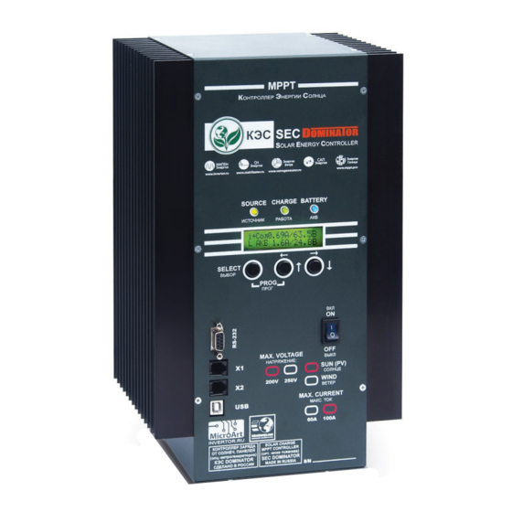
Page 9: Controls And Indication
ATTENTION! ATTENTION! The height of each screwed screw from the wall surface should be no more than 5-6 mm, otherwise the controller internal com- The height of each screwed screw from the wall surface should be no more than 5-6 mm, otherwise the controller internal com- ponents may be damaged. - Page 10 Modes and operational parameters are displayed by the LCD and 3 LEDs: Modes and operational parameters are displayed by the LCD and 3 LEDs: “SOURCE” (Blue LED) – indicates the input voltage level (the state of SP). If the SP voltage exceeds AB voltage for more than 5V then the LED is constantly on. “SOURCE”...
-
Page 11: Wire Diagram Of The Controller Connection
The recommended wire diagram of the controller connection is shown in Picture 4 (the use of current sensors and control relays is not necessary): The recommended wire diagram of the controller connection is shown in Picture 4 (the use of current sensors and control relays is not necessary): WIRE DIAGRAM OF THE CONTROLLER CONNECTION WIRE DIAGRAM OF THE CONTROLLER CONNECTION Picture 4... -
Page 12: First Start, Prestarting Procedures
(high current is not allowed for AB at the end of charge). You should consider that communication via I²C bus is available ONLY with MICROART equipment and connecting cable supplied with the controller set! At the same time, there is no need in ECS2 sensor (MAC inverter transmits its data on currents via I²C bus). If the sensor duplicates the I²C data from the MAC, the controller will produce incorrect charge currents. - Page 13 Connect the loads and/or the alarm system to the external devices control relay if necessary. In case you have an additional equipment like MAC inverter and/or BMS from MICROART or additional controllers, please connect the devices via I²C bus using the connecting cable supplied with controller and make the necessary settings.
-
Page 14: User Settings Editing
USER SETTINGS EDITING All settings (including ECS calibrations) are stored in a non-volatile memory (NVRAM) and they don't depend on the power switch position. When you change the parameter values, after con rming it takes e ect immediately. Control and indication algorithms are extremely close to the MAC inverter ones. The controller has two modes: “Indication”... - Page 15 Page 2 contains information on the currents measured by external current sensors: 0 . 0 PAGE 2 0 . 0 Where: – current measured by an external current sensor – power measured by an external current sensor 1 (Is de ned as the multiplication of voltage by AB current measured by the external current sensor –...
-
Page 16: Settings" Mode
“SETTINGS” MODE “Settings” mode – is a mode where all device operating parameters are set and all needed calibrations can be done. By selecting that mode, you enter the setting menu which consists of the following submenus: 1. AB settings 2. - Page 17 To charge alkaline batteries by means of MPPT Pro controller you must do the following: 1. Select the required AB voltage (12, 24, 48, 96) V. 2. 2. Calculate the required number of cells in series connection (Nc) to achieve the required AB voltage. For example, for KGL cell type the charge voltage is 1,44 V at 25C (degrees Celsius).
- Page 18 To interconnect the devices, you need to use 6-core at cables both sides terminated by RJ12 jack plugs according to the scheme of direct connection Pin-to-Pin. 2.1. “DIRECTION” – a selection of MAC, BMS and other MPPT connection: 1. “Slave” – connection to MAC in “Slave” mode. This connection mode can be used either for Controller working with MAC or without MAC but in the group of controllers operating in parallel for one AB pack.
- Page 19 Controller 0 Controller 1 Controller N “Direction” “Direction” “Direction” ”Slave” ”Slave” ”Slave” “Address selection ”Address selection Address selection Number of slave MPPT” Number of slave MPPT” Number of slave MPPT” “00” “01” “N-1” /BMS/MPPT MODEM “T /BMS” Pic. 2 . Scheme of the system "Multiple Controllers + MAC". Controller 0 Controller 1 Controller N...
- Page 20 Controller 0 Controller 1 Controller N “Direction” “Direction” “Direction” ”Slave” ”Slave” ”Master MPPT” “Address selection ”Address selection Address selection Number of slave MPPT” Number of slave MPPT” Number of slave MPPT” “00” “01” “N-1” Pic. 4. Scheme of the system "Multiple Controllers". Controller 0 “Direction”...
- Page 21 ATTENTION! 1. For the system with multiple Controllers all the AB settings should be the same for all Controllers! 2. Each controller must be connected to its own AB temperature sensor! 3. Each controller must be connected to its own, independent array of Solar Panels! 4.
- Page 22 “INDICATION” In this section, the user can set the most convenient indication mode of the controller current operational data. All displayed parameters are divided into 5 pages. Each page can be set in one of three conditions: “Auto” – The page is changing automatically to another which was also set as (“Auto”) in a period set via section 5.4 “Display time”; “Manual”...
- Page 23 "THRESHOLD VOLTAGES" In this subsection, the user can set SP power thresholds or AB voltage at which the built-in relays are switched ON/OFF. Each relay is rated at 16A/220 V, i.e. For the load below 3.5 kW. Details of the relay operating at SP power excess. The power excess means that SP can produce more power than is being drawn now.
- Page 24 In case of Controller and MAC are connected via special cable and all required settings have been done then the Relay state will also be depended on MAC operating mode. In MAC modes “Charge” and “Network transmitting” the relays are switched on when the “Eco mode” is activated, and O if “Eco mode” is disabled. In other words, the relays connect the load if AC grid is available and disconnect when there is no grid.
-
Page 25: Appendix
APPENDIX APPENDIX 1. MANUAL OPERATING MODE. When the Manual mode (hereinafter MM) is activated, the additional (sixth) page appears in the "Indication" subsection: U p B – Manual Mode indicator; – SP current, A; – (pulse-width modulation) PWM depth – SP voltage, V; (see below);... - Page 26 ATTENTION! Calibration of external current sensors is possible only if the battery is connected and SP current is at least 5A! Calibration procedure: 1. Please connect one ECS to the controller as shown in Pic. 4, by inserting the ECS connector into the corresponding seat of the controller. 2.
- Page 27 Calibration (consists of 2 stages) will start and the following message appears on the LCD: x x . x x * * * W a i t * * * * The calibration process is accompanied by intermittent sound signal. In case the SP current doesn't reach 5 A, the message appears: C a l i b r a t i o n I m p o s s i b l e !
-
Page 28: Appendix
APPENDIX 3. FIRMWARE UPDATE The user may update the controller rmware (hereinafter referred to as FW). For that on the website http://www.invertor.ru in the section of technical support-> rmware and manuals you can nd and download required FW (a loader and FW for the controller – ”Firmware”). As well you can nd there a description of the necessary equipment and all necessary steps. - Page 29 The wire diagram of Wind turbine and Controller connection is shown in picture: The wire diagram of Wind turbine and Controller connection is shown in picture: The wire diagram of Wind turbine and Controller connection is shown in picture: FEATURES OF CONTROLLER OPERATING WITH WIND TURBINE FEATURES OF CONTROLLER OPERATING WITH WIND TURBINE FEATURES OF CONTROLLER OPERATING WITH WIND TURBINE Before WT mounting on the tower please assemble the circuit according to the picture above.
- Page 30 Voltage Limit is calculated as: The Voltage Jumper4 Jumper3 Jumper2 Jumper1 Jumper0 limit Ulim= 85 + 3 * K; Where K is the number from 0 to 31, set by jumper 0 ... 4 in binary format. The table of correspondence for jumpers position, K value and preset voltage limit is given on the left.
- Page 31 USER SETTINGS OF THE CONTROLLER FOR OPERATING WITH WIND TURBINE Select "Wind" in the menu "Operating Modes" submenu "Type of Source". After that go to the menu "Settings" submenu "Source Settings" where WT parame- ters will be available for editing: "RPM to start"- WT rpm when the power takeoff starts.
- Page 32 After all the mentioned above steps are done you can mount WT on the tower, set all required parameters of the AB and other parameters (see the main part of the Manual). After that the system is ready for operating. The indication of the current WT speed appears on page 3 in the upper left corner: w 0 0 0 0 P o u t...
- Page 33 OVERALL AND MOUNTING DIMENSIONS OF THE CONTROLLER COMPONENTS The controller is wall-mounted. Installation should be done on a vertical surface (wall) with a free space of at least 15 cm from the sides and at least 25 cm from the top. Otherwise, it is possible to increase the heating of the controller and therefore reduce the generated power. To mount the product please x 4 screws of proper size in the wall, in accordance with the drawings and x the product on them.
-
Page 34: Appendix
2 holes Electrical heater block. APPENDIX 5. GENERAL RECOMMENDATIONS FOR OPERATION AND CONNECTION OF THE CONTROLLER, SP AND OTHER EQUIPMENT For a minimum comfort in a country house on the latitude of central Russia region, SP total capacity should not be less than 600 W, for example: 3 solar panels of 24V 200W. - Page 35 But it should be noted that the maximum SP idling voltage at the controller input should not exceed 200V/250V (open circuit voltage without load) in any weather conditions. Watch this restriction especially when placing the system in the environments of high solar activity and low temperatures. Approximately, the open-circuit voltage increases at -30°C by 20-25%, i.e.
- Page 36 Perhaps, you have already solved how to "prolong" the daylight hours (by placing SP di erently along the cardinal directions), you have provided the energy arrival even in cloudy weather (by connecting the SP in series in high voltage strings). And after that you have to think how to make the main energy consumers operate during the day and leave a small amount of electrical equipment (LED lamps, TV, computer, etc.) for evening and night to avoid AB discharge, which makes batteries serve for years (of course, much depends on the AB design).
- Page 37 The last option of the refrigerator is the best. Due to a high-quality thermo-insulation, many refrigerators can maintain a low enough temperature inside, even The last option of the refrigerator is the best. Due to a high-quality thermo-insulation, many refrigerators can maintain a low enough temperature inside, even after the power is cut o .
- Page 38 The graph of the ordinary solar system and the "correct" solar system operating with installed SP of 1500-2000W capacity on a cloudy June day. The graph of the ordinary solar system and the "correct" solar system operating with installed SP of 1500-2000W capacity on a cloudy June day. For a detailed description of the graphs (and about the features of using batteries, etc.), see http://www.invertor.ru/vibor.html For a detailed description of the graphs (and about the features of using batteries, etc.), see http://www.invertor.ru/vibor.html In conclusion, we note that for energy saving (which is especially important for the autonomy) it is better to use autonomous sewage system (for example,...
-
Page 39: Warranty Liabilities
WARRANTY LIABILITIES The seller guarantees that the purchased product does not contain the mechanical damages and corresponds to the passport characteristics. The warranty period is 1 year from the date of sale, but not more than 1 year and 4 months from the date of manufacture. Warranty does not apply to: •... -
Page 40: Repair
(when sent as a legal entity). You can nd out the stage of repair by calling LLC “MICROART PRO” multi-line phone: +7 (495) 477-54-51, you have to say the device serial number, or password from receipt for admission to repair (if you delivered device personally) or you can use the link http://s.microart.ru/map. - Page 41 FOR NOTE...
- Page 42 SPECIFICATION WARRANTY CARD (ON THE MODEL OF MAC INVERTER PASSPORT) Date of sale Model Price Sellers signature Price Date of production Voltage (V) Warranty period – 1year from the date of sale, but no more than 1 year Peak current ( ) and 4 months from the date of production.
Need help?
Do you have a question about the Kes DOMINATOR MPPT 200/60 and is the answer not in the manual?
Questions and answers