
Summary of Contents for Jet Cleen JC-UHE130B
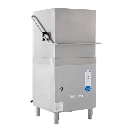
- Page 1 DISHWASHER JC-UHE130B/DH-2000 INSTALLATION, OPERATION AND MAINTENANCE (REV 09/2019)
- Page 2 QUICK GUIDE OPERATION...
- Page 3 WATER DRAIN JC-UHE130B JC-DH-2000 CAUTION: Read the instructions before using the appliance. Children should not play with the appliance. ATTENTION:...
- Page 4 INSTALLATION DIAGRAMS BACK OF THE MACHINE JC-UHE130B JC-DH-2000 1 - DRAIN/DRAIN PUMP 2 - WATER INLET 2 - RINSE AID PUMP 3 - POWER SOURCE 4 - GROUNDING SYSTEM...
-
Page 5: Table Of Contents
INDEX 1 - GENERAL RECOMMENDATIONS .………………...…………………..…..p.5 1A - HANDLING …………………………………………………………………………………..……... p.5 1B - UNPACKING …………….……………………………………………………….………….……….. p.5 1C - DISPOSAL ……………………………………………….………….………………………….…..p.6 1D - TECHNICAL DATA ……………………………………………………..……………………..p.6 2 - INSTRUCTION FOR THE INSTALLER / MAINTENANCE …………..p.7 2A - WATER CONNECTION ……………………….……………………….……………....p.7 2B - ELECTRICAL CONNECTION …………….………………………….…………….……...……... -
Page 6: General Recommendations
- GENERAL RECOMMENDATIONS 1A-HANDLING ATTENTION Read this instruction booklet carefully, as it contains important advice for safe installation, Use suitable means to move the appliance, a lift operation and maintenance of this appliance. truck or fork pallet truck (the forks should Keep this booklet on hand in a safe place for reach more... -
Page 7: Disposal
ELECTRICAL CONNECTION 1C – DISPOSAL Voltage ± 6 % This appliance is marked according to the Frequency ± 1 % European directive 2002/96/EC on Waste Electrical and Electronic Equipment (WEEE). By Wash Cycle °C 55(131F) ensuring this product is disposed of 85(185F) Rinse Cycle °C... - Page 8 - INSTRUCTION FOR INSTALLER / MAINTENANCE ATTENTION 2A – WATER CONNECTION Qualified technicians installing N.B. The shut-off valve must be a single machine are obliged to train the operators the machine about utilization direction, spool, sphere, lid control type, which can shut off the water supply safety procedures to be followed.
-
Page 9: Warning Messages Displayed On The Control Panel
2A3 – MODELS WITH GRAVITY DRAINAGE The manufacturer is not responsible for N.B. injuries caused by improper grounding. The drainage line must comprise of a free flow sump pit of the proper size capable of disposing twice the water flow as The electrical connection must be in indicated on the data diagram. -
Page 10: Detergent And Rinse Aid Dispensers And Settings
Verify that overflow device completely removed and no obstructions are present in the drain line. ACTIONS FOLLOWING WARNINGS: Booster tank heating elements Fig.7 are interrupted, all loads are deactivated, Before removing the front panel make sure the the electronic board displays warning codes machine is disconnected from the main breaker. -
Page 11: Maintenance
2E – MAINTENANCE 1- Descale the boiler, the internal surface of the tank and the appliance water piping once or twice a year. 2- Descale the rinse and wash jets every month using vinegar or a descaling agent. 3- The internal hose of the rinse aid and detergent peristaltic dispenser should undergo periodic maintenance (once or twice a year). -
Page 12: User Instructions
- USER INSTRUCTIONS 3A – GENERAL WITH A MACHINE EQUIPPED RECOMMENDATIONS AND SAFETY MICROSWITCH STOP WARRANTY OPERATION IN CASE DOOR OPENED DURING WORKING appliances have been tested PROCESS. MOTOR PUMP optimised consistently deliver high EQUIPPED WITH A 160°C/320°F reliability and performance. This appliance THERMAL PROBE TO AVOID OVERHEATING. -
Page 13: Standard Loading Racks
The representation of the control panel is meant for the full version of the equipment. Some versions may 3B – STANDARD LOADING RACKS not have all the indicated functions. 1- Load plates in frontal position. (Fig.10) 3C1 – STARTING THE MACHINE 1- Open the door and verify all internal components including the water flow device are in the correct position(Fig.14) -
Page 14: Daily Cleaning / End Of Work
Fig.18 5- Wait until indicator light “F” is OFF and 3D – DAILY CLEANING / END OF an “end” message appears on the display WORK DAY (Fig.19). Open the door and remove Cleaning and user maintenance must not be clean dishes basket. performed by children without supervision. -
Page 15: Warning Messages Displayed On The Control Panel
3E – WARNING MESSAGES 3D3 – FILTERS CLEANING 1- Turn OFF the machine by pressing button DISPLAYED ON THE CONTROL “A” On/Off. PANEL 2- Manually remove the overflow and filters. N.B. If the machine is in the OFF mode, (Fig.25) warning messages will not be visualized on the display. -
Page 16: Troubleshooting
– TROUBLESHOOTING DISHWASHER DOES 4- Verify the rinsing temperature is WORK ? between 80°C (176°F) to 90°C (194°F) degrees. 1- Verify the main water supply inlet is correctly connected, open and CONDENSATION ON GLASSES ? free from any obstructions. 2- Verify 1- Verify if the rinse aid container is main electrical...
Need help?
Do you have a question about the JC-UHE130B and is the answer not in the manual?
Questions and answers