
Summary of Contents for POLYSONICS DCT-7088
- Page 1 Chapter 7088-8000 June 1998 DCT-7088 Portable Digital Correlation Transit Time Ultrasonic Flowmeter POLYSONICS POLYSONICS POLYSONICS POLYSONICS ® Software Version 3.23...
- Page 2 7088-8000 INSTRUCTION MANUAL DCT-7088 PORTABLE DIGITAL CORRELATION TRANSIT TIME FLOWMETER Notice This manual is designed to promote personal and system safety and to optimize product performance. It should be read carefully before installing, using, or maintaining the flowmeter. If a problem occurs that is not resolved in the manual, refer to Chapter 7 for more information on additional service and support.
-
Page 3: Table Of Contents
7088-8000 Table of Contents DCT-7088 Portable Digital Correlation Transit Time Ultrasonic Flowmeter CHAPTER 1: PRODUCT OVERVIEW ..............1-1 1.1 INTRODUCTION ......................1-1 1.2 THEORY OF OPERATION ................... 1-1 1.3 TRANSIT TIME ACCURACY..................1-3 1.4 OPERATING THE FLOWMETER................1-3 1.4.1 RS232 PORT .............................1-3 1.5 POWER .......................... - Page 4 7088-8000 CHAPTER 3: CONFIGURING AND OPERATING THE FLOWMETER 3-1 3.1 KEYPAD AND DISPLAY ....................3-2 3.1.1 KEYPAD AND DISPLAY COMPONENTS....................3-2 3.1.2 DISPLAY CONTRAST AND BACKLIGHT...................3-3 3.2 DIRECT MENU ACCESS....................3-3 3.3 ACCESSING THE MENUS BY SCROLLING ............3-5 3.3.1 SCROLLING THROUGH THE MAIN MENU AND SUB-MENUS ............3-5 3.3.2 SCROLLING THROUGH PRIMARY DISPLAYS, SETUP MENUS, AND DIAGNOSTIC MENUS ........................3-6 3.4 ENTERING DATA IN THE SETUP MENUS ..............
- Page 5 CONFIGURING THE CURRENT LOOP......6-1 CHAPTER 7: SERVICE SUPPORT AND WARRANTY......7-1 7.1 RESOLVING THE PROBLEM ..................7-1 7.2 LOCAL REPRESENTATIVE SUPPORT..............7-1 7.3 CONTACTING POLYSONICS BY PHONE..............7-1 7.4 FACTORY SERVICE...................... 7-2 7.5 FIELD SERVICE ......................7-2 7.6 WARRANTY ........................7-3...
- Page 6 7088-8000 APPENDIX A: POLYLINK FLOWMETER DATA LINK UTILITY...A-1 A.1 HARDWARE REQUIREMENTS ................A-2 A.1.1 PLANTCOM AND PLANTCOM PLUS ....................A-2 A.2 INSTALLING AND RUNNING POLYLINK ............. A-3 A.2.1 RUNNING POLYLINK FROM AN IBM-COMPATIBLE PC ..............A-3 A.2.2 RUNNING POLYLINK FROM A DDF3088 ..................A-6 A.3 REMOTE MONITORING AND CONFIGURING (VT100 MODE) .......
- Page 7 7088-8000 APPENDIX F: CONFIGURING THE DCT SERIES FLOWMETER ™ WITH TimeGATE ..............F-1 F.1 THE ENVIRONMENT ................F-1 TimeGATE ™ F.1.1 DEFINITIONS ............................F-1 F.1.2 MOUSE OPERATION ..........................F-4 F.1.3 KEYBOARD OPERATION ........................F-4 F.2 INSTALLING TimeGATE ™ ..................F-4 F.3 RUNNING ....................F-5 TimeGATE ™...
-
Page 8: Chapter 1: Product Overview
PRODUCT OVERVIEW 1.1 Introduction The DCT-7088 Digital Correlation Transit Time Flowmeter is a member of the Polysonics series of Tyme Flyte ultrasonic instruments. This microprocessor-based instrument is used to measure the flow of clean, homogeneous liquids (liquids without large concentrations of suspended particles or gasses such as air bubbles.) The flowmeter is non-invasive, which... - Page 9 7088-8000 Figure 1-1 Typical Transit Time System Figure 1-2 Flow Profiles...
-
Page 10: Transit Time Accuracy
7088-8000 1.3 Transit Time Accuracy Non-invasive ultrasonic measurements are subject to a variety of effects that can influence measurement accuracy. All ultrasonic instruments are velocity measuring devices and only infer volumetric flow from the operator entered parameter of pipe inside diameter (ID). As this value is squared to get cross-sectional area, a 1% error yields a 2% error in volumetric flow. -
Page 11: Power
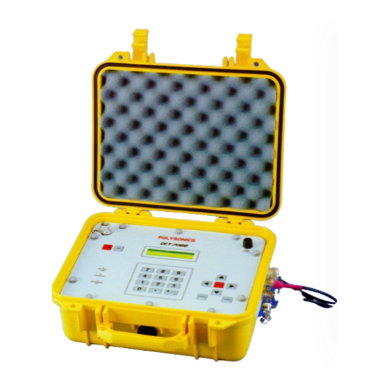
7088-8000 1.5 Power The DCT-7088 is a DC powered instrument that normally operates from an internal 12 volt battery supplied with the unit. It may also be powered by one of the following sources which connect to the 12-15 volt DC input on the breakout box:... - Page 12 7088-8000 Figure 1-3 External Features of the DCT-7088...
-
Page 13: External Features
7088-8000 1.6 External Features The following is a description of the external features of the DCT-7088 (Figure 1-3): Printer Port The printer port provides an output for the optional external thermal printer for printing flow data, diagnostic messages, etc. The printer port connects to a special printer cable which has a 3-pin round connector on the flowmeter end and a DB9 connector on the printer end. -
Page 14: Software Upgrades
(Appendices A and F). The software version number that is installed in the flowmeter is displayed in Menu 94. Contact the local Polysonics representative or the factory to determine the current version available. Software updates are provided either by... -
Page 15: Standard Configuration And Options
7088-8000 1.8. Standard Configuration and Options The standard configuration and options for the DCT-7088 flowmeter are designated by the model code numbers listed in Table 1-1. For example, the model code DCT7088 1 B 16A describes a flowmeter with the following options: 8-hour battery ™... -
Page 16: Technical Specifications
7088-8000 1.9 Technical Specifications Table 1-2 lists the physical, performance, and functional specifications of the DCT-7088: Table 1-2 DCT-7088 Flowmeter Specifications Performance specifications 1 Flow range ±0 to 50 FPS (±0 to 15 MPS). Accuracy ±0.5% of velocity or ±0.05 FPS (0.0152 MPS), typical on a calibrated... -
Page 17: Chapter 2: System Components
7088-8000 SYSTEM COMPONENTS 2.1 Breakout Box Components The breakout box components are illustrated in Figure 2-1. The breakout box connects the flowmeter through the 7-pin circular breakout box connector . The breakout box provides an interface for the following connections: 15 volt DC power input from the battery charger/AC adapter (Section 1.5) 6 volt DC output cable... - Page 18 7088-8000 Figure 2-1 Breakout Box Components...
-
Page 19: Battery Charger/Ac Adapter
7088-8000 2.1.1 BATTERY CHARGER/AC ADAPTER The battery charger/AC adapter has a removable AC power cable and converts 110-250 volt AC to 15 volts DC. The DC power output cable connects to the breakout box at the DC input connector When connected to the breakout box, the battery charger/AC adapter performs the following functions: Charges the flowmeter battery through the 7-pin circular connector Provides immediate power to operate the unit if the battery is discharged... -
Page 20: Slide Track
7088-8000 2.2 Slide Track The transducer slide track (Figure 2-2) comes standard with the DCT-7088. In many applications, the slide track allows the user to accurately space the transducers before mounting them as a single assembly on the pipe. Refer to Section 4.2.1 for procedures and limitations related to the slide track. -
Page 21: Current Loop Wiring And Current Loop Powering Option
To avoid possible damage to the flowmeter due to an accidental short, disconnect power before removing the back cover of the breakout box. CAUTION: (Disconnect the breakout box from the flowmeter and from the AC adapter/battery charger.) Figure 2-3 Current Loop Power Jumper Settings for DCT-7088... - Page 22 7088-8000 After the loop powering option has been set, the current loop wiring should be connected. The current loop has an input terminal and an output terminal (indicated as IN and OUT on the outer breakout box label). Connections for the self-powered option are illustrated in Figure 2-4 and connections for the loop-powered option are illustrated in Figure 2-5.
-
Page 23: Configuring And Operating The Flowmeter
7088-8000 CONFIGURING AND OPERATING THE FLOWMETER This chapter provides step by step procedures for configuring and operating the instrument with the keypad and display. The configuration settings are stored in non-volatile memory to protect them in the event of a power failure. After the flowmeter has been configured, the transducers are spaced and installed on the pipe (Chapter 4). -
Page 24: Keypad And Display
7088-8000 3.1 Keypad and Display The keypad provides access to the microprocessor for configuring the flowmeter. The keypad entries are viewed on the instrument’s 40-character LCD display. During operation, the display indicates the flow rate and totalizer values. The display is backlit for ease of viewing in low-light conditions and has a variable contrast setting (Section 3.1.2). -
Page 25: Display Contrast And Backlight
7088-8000 3.1.2 DISPLAY CONTRAST AND BACKLIGHT The display is backlit for ease of viewing in low-light conditions. To save battery life, the backlight shuts off automatically after several minutes have passed without a keypad entry. The display has a variable contrast setting. Contrast may need to be adjusted as the ambient temperature changes from very hot to very cold. - Page 26 7088-8000 Table 3-1 provides a list of the menu addresses: Table 3-1 Menu Addresses PRIMARY DISPLAYS: TOTALIZER: Flow/Net Totalizer (Menu 00) Totalizer Units (Menu 36) Flow/Velocity (Menu 01) Totalizer Multiplier (Menu 37) Flow/Positive Totalizer (Menu 02) Net Totalizer (Menu 38) Flow/Negative Totalizer (Menu 03) Positive Totalizer (Menu 39) Signal Strength/Low Signal Cutoff (Menu 04)
-
Page 27: Accessing The Menus By Scrolling
7088-8000 3.3 Accessing the Menus by Scrolling A menu can be accessed directly with a two digit address (Section 3.2) or by scrolling through the flowmeter’s menu structure. The menus are organized into the following basic levels: Main Menu Sub-menus Primary Displays, setup menus, and diagnostic menus The Main Menu displays various sub-menus. -
Page 28: Scrolling Through Primary Displays, Setup Menus, And Diagnostic Menus
7088-8000 3.3.2 SCROLLING THROUGH PRIMARY DISPLAYS, SETUP MENUS, AND DIAGNOSTIC MENUS The user can move from one Primary Display, setup menu, or diagnostic menu to another within the same sub-menu by scrolling. Pressing the DOWN ARROW key displays the next display or menu, while pressing the key displays the previous one. -
Page 29: Quick Setup
7088-8000 4. Complete the configuration process by accessing one of the Primary Displays (Menu 00 through 04). IMPORTANT: The flowmeter will not use the new parameters until one of the Primary Displays is accessed. 3.5 Quick Setup The Quick Setup procedure provides the minimal steps required for configuring the flowmeter to enable it to calculate transducer spacing, acquire ultrasonic signal, and measure flow. -
Page 30: Primary Displays, Setup Menus, And Diagnostic Menus
7088-8000 3.6 Primary Displays, Setup Menus, and Diagnostic Menus This section describes the functions of the Primary Displays, the setup menus, and the diagnostic menus. These displays and menus are described in numerical order according to their menu addresses. The menus are also are listed under their appropriate sub-menus (for example PIPE LINER... -
Page 31: Pipe Setup Menus
7088-8000 Flow/Positive Totalizer (Menu 02) The Flow/Positive Totalizer display indicates the flow Flow= 0.00 GPM rate and the totalized flow in the positive flow x0.1Gal direction. This display is available only if the positive totalizer is enabled in Menu 39. Flow/Negative Totalizer (Menu 03) The Flow/Negative Totalizer display indicates the flow Flow=... - Page 32 7088-8000 To enter the pipe OD: 1. Access Menu 10. The following is displayed: Pipe OD 13.87 inches 2. Enter the value for the pipe OD and press ENTER 3. Press the key. DOWN ARROW The following is displayed: Select Option ! ! ! ! Actual ! ! ! !
-
Page 33: Liner Setup Menus
7088-8000 NOTE: The selection OTHER denotes any material not listed. If OTHER is selected, the pipe sound speed (Menu 14) and pipe inside roughness (Menu 15) must be entered. Pipe Sound Speed (Menu 14) This menu is configurable only if was selected OTHER Pipe Sound Speed... - Page 34 7088-8000 Liner Material (Menu 16) This menu is used to select one of the following liner Liner Material materials: *POLYETHYLENE (no liner) NONE TAR EPOXY RUBBER MORTAR POLYPROPYLENE POLYSTYROL POLYSTYRENE POLYESTER POLYETHYLENE EBONITE TEFLON OTHER The selection denotes a material not NOTE: OTHER listed.
-
Page 35: Fluid Setup Menus
7088-8000 Liner Inside Roughness (Menu 19) This menu is available only if was selected for OTHER Liner Roughness the liner material in Menu 16. The liner inside 0.001000 roughness of the OTHER material should be entered in this menu. Data on this parameter is available from the Cameron Hydraulic Data Book published by Ingersoll- Rand. -
Page 36: Transducer Setup Menus
7088-8000 Fluid Sound Speed (Menu 21) This menu is configurable only if was selected OTHER Fluid Sound Speed for the fluid type in Menu 20. The fluid sound speed of 4863.33 FPS OTHER fluid type should be entered in this menu. (Refer to Appendices C and D for information on fluid sound speeds.) If OTHER... -
Page 37: Flow Setup Menus
7088-8000 Transducer Mounting (Menu 24) This menu is used to select one of the following Transducer Mount transducer mounting methods: *V Mt. Z Mt. W Mt. Refer to Section 4.4 for more information on the transducer mounting methods. Transducer Spacing (Menu 25) This view-only menu indicates the required spacing Transducer Spacing between the transducers. - Page 38 7088-8000 3. Press the DOWN ARROW key. The following is displayed: Flow Units Per *Min Hour 4. Select one of the following time unit (per) options: (million gallons) Max Flow Range (Menu 31) and Min Flow Range (Menu 32) These menus are used to enter the minimum and Max Flow maximum flow values for setting the volumetric flow 2000.00 GPM...
- Page 39 7088-8000 Low Flow Cutoff (Menu 34) When a zero flow condition occurs (for example, as Low Flow Cutoff the result of a pump being shut off), internal sloshing, 0.00 GPM check valve leakage, and other fluid movement can prevent the flowmeter from reading total zero. This phenomenon can result in totalizer errors.
-
Page 40: Totalizer Setup Menus
7088-8000 The flowmeter’s response to the LOS condition may be programmed as follows: Drop the reading to zero Hold the last valid reading (but continue to totalize) In addition to these two options, an alarm can be actuated based on the low signal cutoff (Section 3.6.11). - Page 41 7088-8000 Totalizer Units (Menu 36) This menu is used to select one of the following flow Totalizer Units units used by the totalizers: *Gallons GALLONS LITERS (million gallons) MGAL CUBIC FT CUBIC METERS ACRE FT OIL BARRELS LIQUOR BARRELS NOTE: The flow unit selected for the totalizer display may be different from the flow unit selected for the flow rate display.
- Page 42 7088-8000 Net Totalizer (Menu 38) This menu is used to enable or disable the net totalizer. Net Totalizer The net totalizer provides the difference between the *Off positive and negative flow values. For example, if there are 1000 gallons of flow in the negative direction and 3000 gallons of flow in the positive direction, the net totalizer indicates 2000 gallons of net flow.
-
Page 43: Options Setup Menus
7088-8000 3.6.8 OPTIONS SETUP MENUS sub-menu contains the setup menus for OPTIONS several miscellaneous functions, such as selection of English or metric flow units, changing the system and scale factor passwords, and RS232 settings. Measurement Units (Menu 42) This menu is used to select one of the following types Measurement Units of measurement units for the flowmeter: *English... - Page 44 7088-8000 NOTE: To avoid entering parameters “on top of” a previously stored set and losing the old data, ensure that the desired site is active in Menu 43 before entering the new set of parameters. RS232 Configuration (Menu 46) This menu is used to configure the flowmeter’s RS232 port.
- Page 45 7088-8000 NOTE: In addition to the system password, the flowmeter utilizes a scale factor password (Menu 48) to protect only the scale factor setting. If the system password is enabled, the flowmeter Password? requests the system password when the user attempts to enter any configuration data.
- Page 46 7088-8000 Change Scale Factor Password (Menu 48) This menu is used to change the scale factor password. The scale factor password is designed to protect the scale factor from unauthorized or accidental changes. The scale factor password may be enabled or disabled. The flowmeter ships from the factory with the scale factor password disabled.
-
Page 47: Calibration Setup Menus
7088-8000 Unit ID (Identification) Number (Menu 49) This menu is used to set the ID (identification) number Unit ID of the flowmeter. This number is determined by the operator and is used to identify the specific instrument or site. Any whole number between 1 and 60,000 may be entered with the numeric keypad. - Page 48 7088-8000 Zero Set (Menu 51) This menu is used to select one of the following Set Zero zeroing (calibration) methods: ! ! ! ! No Flow ! ! ! ! Manual (zero set calibration) NO FLOW (manual zero set calibration) MANUAL Refer to Section 5.1 for detailed information on the zero set calibration methods.
-
Page 49: Current Loop Setup Menus
7088-8000 NOTE: To keep the current value displayed in any screen, scroll to the next screen with the key instead of pressing DOWN ARROW ENTER Once all time parameters have been entered, the new programmed date and time is displayed: 3.6.10 CURRENT LOOP SETUP MENUS sub-menu contains the setup menus for 4-20mA... -
Page 50: Alarms Setup Menus
ALARMS sub-menu contains the setup menus for programming and viewing the flowmeter’s alarm parameters. The DCT-7088 has four alarms which may be programmed ON or OFF based on flow rate or signal strength values. If the measured value of the... - Page 51 7088-8000 3. Select one of the following alarm ON conditions: NOT PROGRAMMED (OFF) FLOW > (The relay actuates when the flow rate is greater than the ON condition value.) (The relay actuates when the flow rate FLOW < is less than the ON condition value.) (The relay actuates when the signal SIGNAL >...
-
Page 52: Data Log Setup Menus
7088-8000 8. Press the DOWN ARROW key. The Alarm Off Condition Value screen is Off Cond. Value displayed: 24.00 Gal/S 9. Enter the value for the alarm OFF condition and press ENTER 10. Repeat steps 1 through 9 for all alarms that are to be programmed. - Page 53 7088-8000 file numbers can be viewed to determine which data log files are present. These files can be deleted from the flowmeter or can be transferred in ASCII format to an IBM-compatible PC for record keeping or analysis. The files are transferred using the PolyLink flowmeter data link utility (Appendix A).
- Page 54 7088-8000 Prompts are displayed one screen at a time requesting day hour, minute, and second information for the start and stop times:fr 4. Enter the requested time parameters for each screen, pressing after each entry. ENTER NOTE: To keep the current value displayed in any screen, scroll to the next screen with the DOWN ARROW key instead of pressing...
-
Page 55: Diagnostics Display Menus
7088-8000 To delete a data log file: 1. Access Menu 80. 2. Select VIEW 3. Scroll through the data log files with the DOWN ARROW keys to display the file that is to be deleted. 4. Press ENTER The following is displayed: Erase Log File? Are you sure?(5=Yes) 5. -
Page 56: Print Setup And Print Commands
7088-8000 Delta Time/Fluid Sound Speed (Menu 91) This menu displays the value for DeltaT and the fluid DeltaT = 0.00 ns sound speed as measured by the flowmeter. DeltaT is SSpeed = 4863.33 FPS the difference between the upstream and downstream travel time, expressed in nanoseconds. - Page 57 7088-8000 The flow data is printed in minimum, maximum, and average flow rates. The minimum and maximum rates are automatically reset at the end of each print period. The average flow rate is the average over the print interval. To configure the printer: 1.
- Page 58 7088-8000 Prints Diagnostics (Menu 98) All parameters associated with the diagnostics menus (Menus 90 through 94) can be printed out by pressing MENU and 98. Prints Current Screen (Menu 99) Any screen which is currently displayed on the flowmeter can be printed out by pressing MENU and 99.
-
Page 59: Master Erase Function And Emergency Override Passwords
Appendix 3.7 Master Erase Function and Emergency Override Passwords This section covers the emergency override passwords and the procedure for performing a master erase of all configuration data on the flowmeter. Since these two procedures allow critical data to be accessed and changed, this page may be removed from the instruction manual to prevent unauthorized use of these features. -
Page 60: Installing The Transducers
Appendix C INSTALLING THE TRANSDUCERS This chapter covers the procedures for installing the transducers. It covers guidelines for selecting a measurement site (Section 4.1) and describes the procedures for spacing and mounting the transducers (Section 4.2). Three different mounting methods are described: the V method, Z method, and W method (Section 4.4). - Page 61 Appendix C Figure 4-1 Site Recommendations A-61...
-
Page 62: Spacing And Mounting The Transducers
Appendix C 4.2 Spacing and Mounting the Transducers In order to maximize signal strength and accuracy, it is essential to properly space and mount the transducers as follows: 1. Select a proper transducer site, following the guidelines in Section 4.1. 2. -
Page 63: Using The Slide Track
The flowmeter is now capable of accurately measuring velocity and flow. 4.2.1 USING THE SLIDE TRACK The transducer slide track (Figure 4-2) comes standard with the DCT-7088. It may be used for mounting transducers with the V or W mounting method, but cannot be used for the Z method. -
Page 64: Aligning The Transducers
Appendix C To use the slide track: 1. Complete steps 1 through 3 in Section 4.2 to determine the transducer spacing. 2. Ensure that the inside face of the left transducer is aligned to the 0 (zero) spacing mark. If not, loosen the thumb screws and adjust its position accordingly. 3. -
Page 65: Transducer Mounting Methods
Appendix C 4.4 Transducer Mounting Methods There are three methods of mounting the transducers, which are available in Menu 24. The best method is determined by the specific application. The mounting methods are as follows: V method (Section 4.4.1) W method (Section 4.4.2) Z method (Section 4.4.3 4.4.1 V METHOD The V method (Figure 4-4) is considered the standard method. -
Page 66: W Method
Appendix C 4.4.2 W METHOD In many instances, flowmeter performance on small metallic pipes with outer diameters of 2 inches (51 millimeters) or less can be improved by using the W mounting method (Figure 4-5). With the W method, the sound wave traverses the fluid four times and bounces three times off the pipe walls. -
Page 67: Z Method
Appendix C 4.4.3 Z METHOD The signal transmitted in a Z method installation has less attenuation than a signal transmitted in a V method installation. This is because the Z method utilizes a directly transmitted (rather than reflected) signal which transverses the liquid only once. The Z method (Figure 4-6) is used primarily in applications where the V method cannot work due to signal attenuation from excessive air or solids in the liquid, thick scale, poorly bonded linings, or very large pipes. - Page 68 Appendix C To mount the transducers using the Z-method: 1. Complete steps 1 through 4 in Section 4.2. 2. Establish a reference at both the 3 o’clock and 9 o’clock positions of the pipe (Figure 4- Figure 4-7 Establishing a 3 O’clock and 9 O’clock Reference (Z Method) 3.
- Page 69 Appendix C 6. Fold one end of the paper across its width to produce a clean, straight edge (Figure 4-9). 7. Line the fold of the paper up with the horizontal center line of the 3 o’clock transducer (Figure 4-9). Figure 4-9 Wrapping the Gauging Paper Around the Pipe (Z Method) 8.
- Page 70 Appendix C 10. Mark along the new fold (Figure 4-12). Figure 4-12 Marking Along the Fold (Z Method) 11. Draw a horizontal line along the pipe from the center line of the 3 o'clock transducer position (Figure 4-13). Use a level to ensure that the line is level with the top of the pipe.
- Page 71 Appendix C 13. Wrap the paper firmly back on the pipe. Have the point where the ends of the paper come together line up with the horizontal line on the 3 o’clock side of the pipe. Ensure that the inside corner of the straight edge is aligned with the mark made for the transducer spacing.
- Page 72 Appendix C 16. Mount the transducers with pipe straps by following steps 5 through 10 in Section 4.2 (Figure 4-18). Figure 4-18 Mounting the Transducers with Straps (Z Method) Figure 4-19 illustrates the final Z method installation. Figure 4-19 Final Z Mounting Method Installation A-72...
-
Page 73: High Temperature Transducer Blocks
Appendix C 4.5 High Temperature Transducer Blocks Optional high temperature blocks are available for applications with pipe temperatures ranging from 300 to 470$F (150 to 243$C). The blocks are installed between the transducer face and the pipe. ™ Do not use PolyGlide sonic coupling compound in applications where NOTE: temperatures exceed 250°F (121°C). -
Page 74: Nylon (Cloth) Tie-Down Straps
Appendix C ™ PolyGlide sonic coupling compound is in grease form and is made from a mineral oil base. It is rated for temperatures up to 250°F (121.1 °C). Other coupling compounds are recommended for the following applications: ® Silicon RTV (GE RTV-108 or similar) for underground or submerged transducer sites or sites where a more permanent bond is required. - Page 75 Appendix C To release the nylon straps: 1. Pull back on the release pawl “C” located on the ratchet handle. (This allows the handle to be opened without tightening the strap.) 2. While holding the release pawl back, open the ratchet handle to the fully open position. 3.
-
Page 76: Chapter 5: Calibration
Appendix C CALIBRATION An important step in assuring accurate flow measurement is the proper calibration of the instrument and the installation. This chapter provides an overview of the calibration methods applicable to the DCT series of flowmeters. It covers the reasons why these calibration methods are necessary, and the order in which they should be performed. -
Page 77: Preliminary Steps For Zero Set Calibrations
Appendix C 5.1.1 PRELIMINARY STEPS FOR ZERO SET CALIBRATIONS Before performing a zero set calibration, follow these preliminary steps: 1. Ensure that the transducers are connected to the pipe during the zero set calibration procedure. 2. Ensure that the instrument is reading flow. (Completing the Quick Setup procedure [Section 3.5] should accomplish this. -
Page 78: Scale Factor Calibration
Appendix C Table 5-2 illustrates an example of a manual zero offset of 10 gallons per minute: Table 5-2 Example of Manual Zero Set Uncalibrated Flow Reading Manual Zero Offset Calibrated Flow Reading (before manual zero offset) (after manual zero offset) 250 GPM 10 GPM 240 GPM... -
Page 79: Scale Factor Precautions
Appendix C 5.2.1 SCALE FACTOR PRECAUTIONS Observe the following precautions when setting the scale factor: Always determine the scale factor at the highest possible flow rate achievable in order to maximize the accuracy of the scale factor. Use the factory preset scale factor as marked on the transducers in the following situations: The flow cannot be stopped to verify or set the zero point A reasonably high flow rate cannot be achieved... -
Page 80: Configuring The Current Loop
(Section 2.3). To calibrate, test, and set the span for the current loop: 1. Connect a milliammeter to the 4 to 20 mA terminals on the breakout box of the DCT-7088 (Figure 2-1). 2. Access Menu 58: 4 mA Calibrate <--... - Page 81 Appendix C 8. Enter a flow rate which equals the 4 mA (minimum anticipated) reading and press ENTER 9. Press the DOWN ARROW key. The following is displayed: Span? 20 mA 0.00 Gal/S 10. Enter a flow rate which equals the 20 mA (full scale) reading and press ENTER 11.
-
Page 82: Service Support And Warranty
2. Contact the installation contractor or representative through which the instrument was purchased (Section 7.2). 3. Contact Polysonics to attempt to resolve the problem over the phone (Section 7.3). 4. Return the unit to Polysonics for repair (Section 7.4) or arrange for Polysonics field service (Section 7.5). 7.2 Local Representative Support The local Polysonics representative is the first contact for support and is well equipped to answer questions and provide application assistance. -
Page 83: Factory Service
Appendix C 7.4 Factory Service If Polysonics determines that the problem cannot be resolved over the phone, the entire unit should be returned to Polysonics' service department or arrangements made for Polysonics field service (Section 7.5). The Polysonics Service Department should be contacted before returning an instrument for repair. -
Page 84: Warranty
Appendix C 7.6 WARRANTY Peek Measurement products are warranted to be free from defects in material and workmanship at the time of shipment and for one year thereafter. Any claimed defects in Peek Measurement products must be reported within the warranty period. Peek Measurement shall have the right to inspect such products at buyer's plant or to require buyer to return such products to Peek Measurement plant. -
Page 85: Polylink Flowmeter Data Link Utility
TimeGATE utility. PolyLink is available on the PlantCom Utility Software diskette from Polysonics or by modem download from the Polysonics Bulletin Board System (BBS) at (713) 933-1901. (For procedures on using the BBS, refer to the file BBS.TXT, available on the PlantCom Utility Software diskette.) PolyLink is also available in the zipped software upload files for... -
Page 86: Hardware Requirements
RS232 Com Cable. A.1.1 PLANTCOM AND PLANTCOM PLUS Polysonics offers two optional plant communication packages, PlantCom and PlantCom Plus, which provide the following hardware for use with PolyLink: PlantCom: a 6 ft (1.83 m) null modem cable (DB25 female to DB25 female) and two adapters (DB25 male to DB9 female). -
Page 87: Installing And Running Polylink
Appendix C A.2 Installing and Running PolyLink The procedures for installing and running PolyLink vary slightly, depending on whether PolyLink is run from an IBM-compatible PC (Section A.2.1) or a DDF3088 (Section A.2.2). PolyLink comes in the self-extracting zipped file PLXXXZ.EXE. The zipped file name used in these procedures includes the letters XXX and Z. - Page 88 Appendix C 4. Create a directory called DDF (if the DDF directory does not already exist). NOTE: To create the DDF directory, enter the following commands at the C: prompt one at a time, pressing ENTER after each one: MD DDF 5.
- Page 89 Appendix C The message CONNECTING..is displayed for several seconds while the PC and the flowmeter attempt to establish communication. If the units connect, the VT100 screen is displayed (Figure A-1). If the units do not connect, the RS232 settings may need to be reconfigured (Section A.4) or Windows may still be running in the background.
-
Page 90: Running Polylink From A Ddf3088
2. Screw the round connector of the optional RS232 Com Cable into the RS232 port of the DDF3088. (The RS232 port is located on the top left of the instrument farthest from the Polysonics logo [Figure A-2].) Figure A-2 Connecting the RS232 Com Cable to the DDF3088... - Page 91 For instructions on using HCOM, refer to the text file HCOM.TXT on the Polysonics Bulletin Board System (BBS) or on the PlantCom Utility Software diskette. It may be necessary to delete some or all of the data log files with HCOM if insufficient disk space is available for installing PL.EXE.
-
Page 92: Remote Monitoring And Configuring (Vt100 Mode
Appendix C A.3 Remote Monitoring and Configuring (VT100 Mode) When PolyLink successfully connects to one of the following flowmeters, the VT100 screen is displayed: DDF4088 DCT-7088 DDF4488 ISTT DCT-6088 ISTT-P VT100 mode provides the ability to remotely monitor and configure the flowmeter. From the VT100 screen, additional functions can be selected by pressing the appropriate function keys listed at the bottom of the screen (Figure A-1). - Page 93 Appendix C To enter the Diagnostic Display mode from the normal VT100 mode, press on the remote terminal keyboard. The following is displayed: UNIT I.D. #0 ISTT DIAGNOSTIC DISPLAY 00:00 00-00-00 UP DOWN SCALE .09850 FACTOR..WIN_DLY ZERO OFFSET 0.00 (us)..
- Page 94 Appendix C Figure A-3 Diagnostic Display Screen (ISTT/ISTT-P) Pressing a second time exits the Diagnostic Display mode and returns the display to the normal VT100 mode. The Diagnostic Display Mode is not available for the ISTT or ISTT-P when NOTE: running PolyLink on a DDF3088.
-
Page 95: Rs232 Setup
Appendix C A.4 RS232 Setup If the remote terminal has difficulty connecting with the flowmeter, the RS232 settings may need to be reconfigured. If so, the CONNECTING..message is displayed for approximately 30 seconds and the following message is displayed: COMMUNICATION ERROR PRESS ESC KEY TO EXIT POLYLINK, ANY OTHER KEY TO SETUP RS232... -
Page 96: Data Logger
Appendix C A.5 Data Logger Data log files can be deleted from the flowmeter’s memory or transferred from the flowmeter to a remote terminal for record keeping and analysis. In addition, if PolyLink is run from a DDF3088, the transferred data log files can be viewed in strip chart format (Section A.5.2). -
Page 97: Transferring A Data Log File
Appendix C A.5.1 TRANSFERRING A DATA LOG FILE To transfer a data log file: 1. From the Data Logger screen, use the arrow keys to select a data log file. 2. Select TRANSFER FILE The following message is displayed: ENTER DESTINATION FILE NAME: 3. -
Page 98: Deleting A Data Log File
4088XXXZ.EXE. (Wherever a file name in these procedures contains the letters XXX, the current software version number should be substituted for the Xs.) The software upgrade file is available on diskette from Polysonics or by modem download from the Polysonics Bulletin Board System (BBS) at (713) 933-1901. (For procedures on using the BBS, refer to the file BBS.TXT, available on the PlantCom Utility Software... -
Page 99: Upgrading The Flowmeter Software With Polylink
Appendix C A.6.1 UPGRADING THE FLOWMETER SOFTWARE WITH POLYLINK This section describes how to upgrade the flowmeter’s software using the PolyLink utility. For initial software upgrades of the DDF4088 (that is, DDF4088 upgrades IMPORTANT: from version 1.0 to any other version), a utility other than PolyLink is used. Refer to Section A.6.2. - Page 100 Use the HCOM utility to delete all unnecessary files from the C:\T directory. (For instructions on using HCOM, refer to the text file HCOM.TXT on the Polysonics Bulletin Board System [BBS] or on the PlantCom Utility Software diskette.) Use HCOM to transfer PL.EXE and 4088.EXE to the C:\T directory.
- Page 101 Appendix C 7. From the VT100 screen select S/W UPLOAD The Software Upload Screen is displayed: Software Upload ENTER FLOWMETER PROGRAM FILE NAME: Figure A-6 Software Upload Screen 8. Enter 4088.EXE and press ENTER A rotating cursor is displayed indicating that the file is transferring to the flowmeter. After the transfer is complete, the following message is displayed: UPLOAD COMPLETE.
-
Page 102: Initial Upgrades Of The Ddf4088 (Non-Polylink Upgrade
Appendix C NOTE 1: If a prompt is displayed on the DDF4088 requesting a serial number, refer to Section A.6.3. NOTE 2: If the software upgrade was performed from a DDF3088, the software upgrade files should be deleted from the DDF3088 using the HCOM utility. This allows more space for recording data log files. - Page 103 Appendix C 5. Go to the C: prompt on the PC. IMPORTANT: If Windows is running on the PC, totally exit Windows before going to the C: prompt. Do not click on the MS-DOS prompt icon as a means of going to the C: prompt as this may cause connectivity problems.
- Page 104 Use the HCOM utility to delete all unnecessary files from the C:\T directory. (For instructions on using HCOM, refer to the text file HCOM.TXT on the Polysonics Bulletin Board System [BBS] or on the PlantCom Utility Software diskette.) Use HCOM to transfer the unzipped files listed above to the C:\T directory.
- Page 105 Appendix C 10. Enter UPGR4088 and press ENTER if the cable is connected to com port 1. NOTE: The DDF3088 uses com port 1. A flashing cursor appears in the upper left corner of the screen. If the cable is connected to a com port other than com port 1, do not enter NOTE: UPGR4088.
- Page 106 Appendix C 18. Enter 4088.EXE and press ENTER The following is displayed: UPLOAD 4088.EXE ASCII OR XMODEM (A OR X): 19. Press for XMODEM. (Do not press ENTER The following message is displayed: UPLOADING 4088.EXE XXXXX BYTES, XXX BLOCK(S) TRANSFER TIME: X MIN X SEC NOTE: If a DDF3088 is used, the LCD cannot display the entire message due to space limitations.
-
Page 107: Entering The Serial Number For Ddf4088 Upgrades
Appendix C 25. Exit from the upgrade procedure by holding down the key while pressing NOTE 1: If a prompt is displayed on the DDF4088 requesting a serial number, refer to Section A.6.3. NOTE 2: If using a DDF3088, complete the following steps: Exit the upgrade procedure by restarting the DDF3088. - Page 108 Appendix C Figure A-7 Signal Analysis Screen (Signal Displayed in the Frequency [FFT] Domain) Figure A-8 Signal Analysis Screen (Signal Displayed in the Time [SIG] Domain) A-108...
- Page 109 Appendix C To use the signal analysis function: 1. From the VT100 screen, select SIG. ANAL. The Signal Analysis screen is displayed: Figure A-9 Signal Analysis Screen (with Interference Present) In the example displayed in Figure A-9, the desired signal appears as a typical bell-shaped curve on the left.
- Page 110 Appendix C 4. Position the brackets until the interference signal is enclosed by the brackets (Figure A-10): Figure A-10 Positioning Brackets around Interference Frequency A-110...
- Page 111 Appendix C 5. Select SET FILTER to set the filter and reject the bracketed frequencies (Figure A-11). The signal is displayed with the frequencies rejected: Figure A-11 Signal with Frequencies Rejected Several filters can be in effect simultaneously by repeating steps 4 and 5 for NOTE: each desired filter.
-
Page 112: Appendix B: Pipe Schedules
Appendix C PIPE SCHEDULES This appendix provides pipe schedules as a convenient reference for the following pipe materials: Steel, stainless steel, and PVC (Table B-1) Cast iron (Table B-2) Ductile iron (Table B-3) The inside diameters (IDs) listed in the following tables are calculated from the outside diameter and minimum wall thicknesses as specified in applicable standards. - Page 113 Appendix Table B-1 Steel, Stainless Steel, and PVC Pipe Standard Schedules Inside Diameter (ID) and Outside Diameter (OD) in Inches al Pipe Outside Sched. 5 Sched. 10 Sched. 20 Sched. 30 Sched. 40 Sched. 60 Sched. 80 Sched. 100 Sched. 120 Sched.
- Page 114 7088-8000 Table B-2 Cast Iron Pipe Standard Classes Inside Diameter (ID) and Outside Diameter (OD) in Inches Class A Class B Class C Class D Class E Class F Class G Class H minal 3.80 3.02 3.96 3.12 3.96 3.06 3.96 3.00 4.80...
- Page 115 7088-8000 Table B-3 Ductile Iron Pipe Standard Classes Inside Diameter (ID) and Outside Diameter (OD) in Inches Inside diameter Cement lining minal Outside Standard Double e Size Diameter (OD) Class 50 Class 51 Class 52 Class 53 Class 54 Class 55 Class 56 Thickness Thicknes...
-
Page 116: Relationship Between Specific Gravity, Viscosity, And Sound Velocity For Petroleum Products
7088-8000 RELATIONSHIP BETWEEN SPECIFIC GRAVITY, VISCOSITY, AND SOUND VELOCITY FOR PETROLEUM PRODUCTS Figure C-1 is a graph showing the approximate relationship between specific gravity, viscosity and sound velocities for aliphatic hydrocarbons (petroleum products). -116... - Page 117 Appendix Figure C-1 Approximate Relationship between Specific Gravity Viscosity, and Sound Velocity for Petroleum Products -117...
-
Page 118: Appendix D: Fluid Sound Velocities And Kinematic Viscosities
7088-8000 FLUID SOUND VELOCITIES AND KINEMATIC VISCOSITIES The information in the following "Fluid Sound Velocities and Kinematic Viscosities" table is based on material from the Cameron Hydraulic Data Book (17th ed., Ingersoll-Rand, 1988) and Tables of Physical and Chemical Constants (13th ed., Longmans, 1966). -118... - Page 119 Appendix t 0 0 0 0 C t 0 0 0 0 F LIQUID c(m/s) c(ft/s) Acetaldehyde CH 16.1 0.305 0.295 Acetic acid 1584 5196 10% ..........1.35 50% ..........2.27 80% ..........2.85 Conc.-glacial ........1.34 Acetic anhydride 1384 4540 0.88 Acetone CH...
- Page 120 7088-8000 t 0 0 0 0 C t 0 0 0 0 F LIQUID c(m/s) c(ft/s) Asphalt, blended RC-0, MC-0, SC-0 ......159 - 324 37.8 60 - 108 RC-1, MC-1, SC-1 ......37.8 518 - 1080 159 - 324 RC-2, MC-2, SC-2 ......
- Page 121 7088-8000 t 0 0 0 0 C t 0 0 0 0 F LIQUID c(m/s) c(ft/s) Benzene (Benzol) C 1321 4333 0.744 1.00 Benzophenone 1316 4316 Bismuth 1663 5455 Bone Oil 54.4 47.5 11.6 Bromine 0.34 Bromobenzene 1074 3523 Bromoform 2978 Butane-n -1.1...
- Page 122 7088-8000 t 0 0 0 0 C t 0 0 0 0 F LIQUID c(m/s) c(ft/s) Chloroform 0.38 3264 0.35 Cocoanut oil 37.8 29.8 - 31.6 54.4 14.7 - 15.7 Cod oil 37.8 32.1 54.4 19.4 Corn oil 54.4 28.7 Corn starch solutions 22 Baume.........
- Page 123 7088-8000 t 0 0 0 0 C t 0 0 0 0 F LIQUID c(m/s) c(ft/s) Diesel fuel oils 2D ............ 37.8 2 - 6 54.4 1. - 3.97 3D ............ 37.8 6 - 11.75 54.4 3.97 - 6.78 4D ............ 37.8 29.8 max 54.4...
- Page 124 7088-8000 t 0 0 0 0 C t 0 0 0 0 F LIQUID c(m/s) c(ft/s) Formaldehyde 1587 5205 Formamide 1610 5281 Formic acid 1299 4261 10% ..........1.04 50% ..........80% ..........Conc..........1.48 Freon -11 ............ 21.1 0.21 -12 ............
- Page 125 7088-8000 t 0 0 0 0 C t 0 0 0 0 F LIQUID c(m/s) c(ft/s) Glycerine 1923 6307 100% ..........20.3 37.8 50% Water ........5.29 1.85cp Glucose 37.8 7.7M - 22M 65.6 880 - 2420 Guaicol 1252 4107 Helium -268.8 179.8...
- Page 126 7088-8000 t 0 0 0 0 C t 0 0 0 0 F LIQUID c(m/s) c(ft/s) Machine lubricants #8..........37.8 23 - 34 54.4 13 - 18 #10........... 37.8 34 - 72 54.4 18 - 25 #20........... 37.8 72 - 83 54.4 25 - 39 #30...........
- Page 127 7088-8000 t 0 0 0 0 C t 0 0 0 0 F LIQUID c(m/s) c(ft/s) Methyl alcohol 1121.2 3678 Methyl bromide 2968 Methyl iodide 0.213 2673 Methylene bromide 971.2 3186 Methylene chloride 23.5 1064 3490 Methylene iodide 977.7 3207 Milk 1.13 Molasses...
- Page 128 7088-8000 t 0 0 0 0 C t 0 0 0 0 F LIQUID c(m/s) c(ft/s) 54.4 26.4 Paraldehyde 1197 3926 Peanut oil 37.8 54.4 23.4 l-Pentadecene 1351 4431 Pentane 1008 3306 iso-Pentane 3231 n-Pentane -17.8 0.508 1044 3424 26.7 0.342 Petrolatum 54.4...
- Page 129 7088-8000 t 0 0 0 0 C t 0 0 0 0 F LIQUID c(m/s) c(ft/s) Sodium chloride (fused) 1991 1562 6530 5% ............ 1.097 25% ..........15.6 Sodium hydroxide (caustic soda) 20% ..........18.3 30% ..........18.3 10.0 Soya bean oil 37.8 35.4 54.4...
- Page 130 7088-8000 t 0 0 0 0 C t 0 0 0 0 F LIQUID c(m/s) c(ft/s) Sulphuric acid 14.6 100% ..........95% ..........14.5 60% ..........Tar, coke oven 21.1 600 - 1760 37.8 141 - 308 Tar, gas house 21.1 3300 - 66M 37.8...
- Page 131 7088-8000 t 0 0 0 0 C t 0 0 0 0 F LIQUID c(m/s) c(ft/s) Varnish, spar 37.8 Water distilled ..........1482.9 4864 1.0038 fresh ..........15.6 1.13 54.4 0.55 sea ............ 1.15 Water (sea) 1507.4 4944 (surface, 3.5% salinity) Whale oil 37.8 35 - 39.6...
-
Page 132: Appendix E: Glossary
7088-8000 GLOSSARY This appendix provides a glossary of terms that may be useful when using the DCT-7088. Accuracy The ability of a flowmeter to produce an output within a specific tolerance (in comparison to a known standard) which corresponds to its characteristic curve. Refer to Linearity. - Page 133 The lowest speed at which liquid can travel and still be accurately measured. North American standards agency that rates instrument National Electrical Manufacturers enclosures according to their application. The DCT-7088 Association (NEMA) meets NEMA-6. Newtonian and A Newtonian liquid is one which has a linear relationship...
- Page 134 Any signals received by the flowmeter other than the transmitted signal. Positive zero The feature on Polysonics meters which inhibits backflow indication or volume accumulation under zero flow conditions. Setting the low flow or low signal cutoffs to appropriate values can accomplish this.
- Page 135 7088-8000 Totalizer A feature of the flowmeter that accumulates the total volume of fluid that flows past the transducers. The flowmeter has a positive totalizer, a negative totalizer, and a net totalizer. The positive totalizer accumulates the total volumetric flow in the positive (upstream) direction. The negative totalizer accumulates the total volumetric flow in the negative (downstream) direction.
- Page 136 7088-8000 Zero point The amount of offset applied to all flow rates to enable the flowmeter to read zero. All flow below this point is considered negative flow. A small adjustment to the zero point which may be Zero set calibration required to maximize accuracy at low flow rates (Section 5.1).
-
Page 137: Configuring The Dct Series Flowmeter With Timegate
7088-8000 CONFIGURING THE DCT SERIES FLOWMETER WITH TimeGATE ™ After the DCT series flowmeter has been installed, it is ready to be configured and placed in operation. The flowmeter can be configured with an IBM-compatible PC and ® TimeGATE ™, a Windows95 -based configuration and graphical signal analysis utility. - Page 138 7088-8000 Tabs, Option Groups, Lists, and Menus The “folder tab” heading on the screen (Figure F-1) that displays a group of related functions (for example, the CONFIGURATION tab). The configuration parameters for the flowmeter are located on these tabs. Only one tab can be accessed at a time by clicking on the tab’s title.
- Page 139 7088-8000 Pull-down list A list of additional selections for an option. If a pull-down list is available, it can be displayed by clicking on the down arrow to the right of the current selection (Figure F-4). Figure F-4 Pull-Down List Pull-down menus The , and options displayed...
-
Page 140: Mouse Operation
7088-8000 F.1.2 MOUSE OPERATION Follow these guidelines when using a mouse in ™ TimeGATE Use the left mouse button for most standard mouse operations. To select an item, click on it. To select an item from a pull-down list, first open the list by clicking on the down arrow located to the right of the list. -
Page 141: Running Timegate
7088-8000 F.3 Running ™ TimeGATE After installing (Section F.2), the program can be run as follows: TimeGATE ™ 1. Open the door of the flowmeter and connect a null modem cable from the com port of the flowmeter to the com port of the PC. 2. -
Page 142: Configuring The Flowmeter
7088-8000 F.4 Configuring the Flowmeter The setup options are located on the tab in four separate screens. A list CONFIGURATION of the option groups contained in the screens is displayed in the Options Column on the left. By clicking on an option group in the column, the appropriate configuration screen is displayed (Figures F-10 through F-13). - Page 143 7088-8000 Figure F-11 Configuration Screen 2 Figure F-12 Configuration Screen 3 -143...
- Page 144 7088-8000 Figure F-13 Configuration Screen 4 General Configuration Procedures Follow these general steps when configuring the flowmeter: 1. Go to the CONFIGURATION tab. 2. Follow the step by step procedure in Sections F.4.1 through F.4.11 to set the parameters for each option (for example, PIPE TRANSDUCER , and...
-
Page 145: Pipe Option Group
7088-8000 4. Click on the GRAPH tab (Section F.5) to view the flow, velocity, signal strength, and totalized flow values. (It takes several seconds for the full effects of the new configuration to be applied to the flow data.) 5. Save the configuration data to a file for future retrieval by selecting from the SAVE AS FILE... - Page 146 7088-8000 The pull-down list for the pipe OD measurement units is displayed, which includes: INCHES (millimeters) 4. Click on the desired measurement unit. Selecting the measurement unit for pipe OD IMPORTANT: INCHES automatically selects English versus metric units for the following: Pipe OD Pipe wall thickness Liner thickness...
- Page 147 7088-8000 The selection denotes any material not listed. If IMPORTANT: OTHER OTHER selected, the pipe sound speed and pipe inside roughness must be entered. -147...
-
Page 148: Liner Option Group
7088-8000 Pipe Sound Speed Pipe sound speed is configurable only if was selected as the pipe material. If OTHER OTHER was not selected, the pipe sound speed is available for viewing only. To set the pipe sound speed: 1. From the options group, click on the text box. - Page 149 7088-8000 Liner Material To select the liner material: 1. From the options group, click on the down arrow to the right of the LINER MATERIAL text box. The following selections are displayed: (no liner) NONE TAR EPOXY RUBBER MORTAR POLYPROPYLENE POLYSTYROL POLYSTYRENE POLYESTER...
-
Page 150: Fluid Option Group
7088-8000 F.4.3 FLUID OPTION GROUP option group is accessed by clicking on in the Options Column. This FLUID FLUID group contains the options related to the fluid. Fluid Type To select the fluid type: 1. From the FLUID options group, click on the down arrow to the right of the TYPE text box. -
Page 151: Transducer Option Group
7088-8000 Fluid Viscosity Fluid viscosity is configurable only if was selected as the fluid type. If OTHER OTHER was not selected, the fluid viscosity is available for viewing only. To set the fluid viscosity: 1. From the options group, click on the text box. -
Page 152: Calibration Option Group
7088-8000 Transducer Spacing Based on the setup parameters, ™ automatically calculates the required TimeGATE transducer spacing. The spacing parameter is displayed in the SPACING text box. This value is for display only and is not editable. Refer to Section 4.2 for more information on transducer spacing. - Page 153 7088-8000 Preliminary Steps Before performing a zero set (zero flow set or manual zero set) calibration, follow these preliminary steps: 1. Ensure that the transducers are connected to the pipe during the zero set calibration procedure. 2. Ensure that the instrument is reading flow. The instrument must have successfully completed its internal configuration process as indicated by the presence of a flow reading on the Graph screen (Section F.5).
- Page 154 7088-8000 Repeat steps 1 through 3 when the flow rate is within recommended limits. Flow should be greater than -.25 and less than +.25 feet per second (-0.076 and +0.076 meters per second), as displayed on the GRAPH screen. -154...
- Page 155 7088-8000 Manual Zero Set Method The zero point can be manually entered with the manual zero set method. This method should be used infrequently. Manual zero set applies a constant offset entered by the user to all readings. Table F-2 illustrates an example of a manual zero offset of 10 gallons per minute: Table F-2 Example of Manual Zero Offset Uncalibrated Flow Reading...
- Page 156 7088-8000 13. Enter the value of the zero point as determined in step 12 in the text box to the right of ZERO FLOW button. NOTE: A negative offset may be entered by first typing a minus sign. 14. Click on the SEND button again to resend the data to the flowmeter.
-
Page 157: Flow Option Group
7088-8000 F.4.6 FLOW OPTION GROUP option group is accessed by clicking on in the Options Column. This FLOW FLOW group contains the options related to flow, including flow units, damping, and cutoffs (low signal and low flow). Flow Units Both the volumetric units and the associated time rate (per) units are selectable for flow. To select the flow units: 1. - Page 158 7088-8000 Minimum and Maximum Flow Range Values The minimum and maximum values can be set for the volumetric flow range. Setting the optimum flow range generally improves the flowmeter’s response time. Whenever the pipe ID is changed, the flowmeter returns the volumetric flow NOTE: range to its default settings.
- Page 159 7088-8000 For example, if a low flow cutoff of 0.1 feet per second (.03 meters per second) is entered, the instrument would be driven to zero for flow rates less than 0.1 foot per second in the positive direction and greater than -0.1 foot in the negative direction (Figure F-17). -0.3 -0.2 -0.1 +0.1 +0.2 +0.3...
-
Page 160: Totalizer Option Group
7088-8000 F.4.7 TOTALIZER OPTION GROUP option group is accessed by clicking on in the Options TOTALIZER TOTALIZER Column. This group contains the options related to the totalizers, including selecting the totalizer units and the totalizer multiplier. There are three totalizers available: Positive totalizer Negative totalizer Net totalizer... - Page 161 7088-8000 Totalizer Units The totalizer unit which is selected can be different from the flow rate unit. For example, if the flow rate is measured in gallons per minute, the totalizer can be measured in millions of gallons. To select the totalizer unit: 1.
- Page 162 7088-8000 2. Click on the desired totalizer multiplier. -162...
-
Page 163: 4-20 Ma Current Loop Option Group
7088-8000 F.4.8 4-20 mA CURRENT LOOP OPTION GROUP option group is accessed by clicking on in the Options Column. 4-20 mA 4-20 mA This group contains the options for calibrating and testing the current loop and setting the current loop span. The present value of the current loop output is displayed in milliamperes above the test/calibration slide bar. - Page 164 7088-8000 4. Connect an ammeter to the input (IN) and output (OUT) terminals of the current loop module and turn on the ammeter. 5. Click on the NEXT> command button. The next Current Loop Calibration screen (Step 2 of 5) is displayed. 6.
- Page 165 7088-8000 The last Current Loop Calibration screen (Step 5 of 5) is displayed (Figure F-20): Figure F-20 Current Loop Calibration Screen (Step 5 of 5) The current loop can be tested by changing the output of the flowmeter and comparing it to the reading on the ammeter.
-
Page 166: Relays Option Group
7088-8000 Setting the Current Loop Span After the current loop has been calibrated, the span (flow rate associated with the 4 to 20 mA output) can be set. To set the span: 1. From the options group, click on the check box to enable the current 4-20 mA 4-20 mA... - Page 167 7088-8000 The net totalizer can either increment or decrement depending upon the direction of the flow. Since the external totalizer (driven by the net totalizer pulse) can only increment, the flowmeter stops transmitting pulses whenever negative flow is being measured. The flowmeter keeps track of the negative flow and does not start sending pulses to the external totalizer until the measured negative flow has been canceled out by positive flow.
- Page 168 7088-8000 5. Click on the desired ON condition selection. 6. Click on the down arrow of the second pull-down list. -168...
-
Page 169: Options Group
7088-8000 The “greater than” and “less than” modifiers are displayed: > < 7. Click on the desired modifier. 8. Click on the ON condition text box (on the right) and enter the ON condition value. 9. Set the relay OFF condition in a manner similar to setting the ON condition (steps 4 through 8). - Page 170 7088-8000 2. Enter the name of the unit, using any combination of alpha-numeric characters. -170...
-
Page 171: Display Option Group
7088-8000 3. Click on the UNIT ID text box 4. Enter the identification number of the unit, using any whole number between 1 and 60,000. F.4.11 DISPLAY OPTION GROUP option group is accessed by clicking on in the Options Column. DISPLAY DISPLAY This function is applicable only to DCT1088 flowmeters which have the optional display. -
Page 172: Viewing The Flow Data In The Graph Tab
7088-8000 F.5 Viewing the Flow Data in the Graph Tab After the flowmeter has been configured (Section F.4), the values for signal strength, velocity, flow rate, and totalized flow can be observed in the GRAPH tab (Figures F-21 through F-23). In addition to numerical flow data, a graphical representation of a signal sample is displayed for analysis. - Page 173 7088-8000 Figure F-21 Graph with 0.5 Microseconds per Division (example) Figure F-22 Graph with 1.0 Microseconds per Division (example) -173...
- Page 174 7088-8000 Figure F-23 Graph with 5.0 Microseconds per Division (example) The Y axis can also be displayed with one of several scaling factors. To select a scale for the Y axis, click on the down arrow to the right of the text box (located in the upper right corner of the graph) and click on one of the following Y scaling factors:...
-
Page 175: Rs232 Communications
7088-8000 F.6 RS232 Communications This section describes RS232 communications for and how to transmit a TimeGATE ™ communications test message for diagnostic purposes. The baud rate and com port are the only RS232 parameters that can be selected for ™ . -
Page 176: Changing The Baud Rate On The Flowmeter
7088-8000 When TimeGATE ™ cannot connect and the cause is unknown, complete the following steps in order from the Connecting Screen until the units connect: 1. Ensure that the cable connections are tight and that the cable is a null modem cable. 2. - Page 177 7088-8000 can be selected. The baud rate on the flowmeter can be changed using ™ only TimeGATE when is connected online. TimeGATE ™ -177...
-
Page 178: In An Offline Session
7088-8000 To change the baud rate on the flowmeter: 1. Connect online with TimeGATE ™ (Section F.3). 2. From the OPTIONS group on the CONFIGURATION tab, click on the down arrow to the right of the FLOWMETER BAUD RATE text box. 3. -
Page 179: Manufacturing Data
7088-8000 Figure F-26 Communications Test Message (example) 2. To exit the test function, click on CANCEL F.7 Manufacturing Data tab (Figure F-27) contains flowmeter software and hardware MANUFACTURING information used by the factory. This information is not configurable by the user. -179... - Page 180 7088-8000 Figure F-27 Manufacturing Tab -180...
-
Page 181: Master Erase Function
7088-8000 The following information is displayed on the MANUFACTURING tab: Sales order number The following hardware information: Hardware version number Serial number Manufacturing date Unit type Number of channels Flowmeter software version number F.8 Master Erase Function This section describes the procedure for performing a master erase of all user-entered configuration data on the flowmeter. - Page 182 7088-8000 Figure F-29 Mini Bios Options Screen 5. Click on the MASTER ERASE button. The Master Erase Confirmation Screen is displayed (Figure F-30): Figure F-30 Master Erase Confirmation Screen 6. Type yes in the text box of the Master Erase Confirmation Screen and click on the button.
-
Page 183: Upgrading The Flowmeter Software
7088-8000 F.9 Upgrading the Flowmeter Software The version number for the flowmeter’s software can be viewed in the Manufacturing Tab (Section F.7). The flowmeter can be upgraded in the field by downloading new software into its Flash memory. The software upgrade file is available on diskette from Peek Measurement or by modem download from the Peek Measurement web site at www.peekmeas.com. - Page 184 7088-8000 If the software upgrade file is in a location other than drive A, alter the NOTE: command accordingly. For example, if upgrading a DCT1088 and the diskette is in drive B, enter B:\1088.HEX. -184...
- Page 185 7088-8000 The upgrade may take several minutes to complete. While the software is being downloaded, the Download Status Screen is displayed (Figure F-32): Figure F-32 Download Status Screen The Mini Bios Options Screen is displayed again (Figure F-29). 7. Run the new software by clicking on the START PROGRAM button on the Mini Bios Options Screen.
- Page 186 7088-8000 -186...
Need help?
Do you have a question about the DCT-7088 and is the answer not in the manual?
Questions and answers