Table of Contents
Advertisement
Quick Links
Advertisement
Table of Contents

Related Manuals for JSTRON A6 PLUS

Summary of Contents for JSTRON A6 PLUS
-
Page 2: Table Of Contents
Contents 1. Product description.................1 1.1 Product statement..................1 1.2 Trademarks....................1 1.3 Safety instructions..................2 1.4 Product accessories..................3 2. Product overview................4 2.1 Product profile....................4 2.2 Product characteristics..................4 2.3 Product model....................6 3. Appearance introduction..............7 3.1 Product size....................7 3.2 Front panel....................8 3.2.1 Console lighting................8 3.2.2 Touchscreen..................8 3.2.3 Destination selection..............8 3.2.4 Layer selection................9 3.2.5 OLED screen..................9... - Page 3 Contents 6.2.5 Layer shortcut function ............…33 6.2.6 Switch................... …35 6.3 System setting ..................…35 6.3.1 Advanced setting ............... …37 6.3.2 Backup................... …37 6.3.3 Hardware ..................…37 6.3.4 Update................... …38 6.3.5 EN/ Chinese................. …38 7. Case analysis .................39 8. Troubleshooting ................42 9.
-
Page 4: Product Description
Product description 1.1 Product statement The manual shall not be copied, transcribed or translated in whole or part, or disclosed commercially in any means (electronic, mechanical, photocopying, recording or other possible means) or used for any commercial profit without prior written consent of our company. -
Page 5: Safety Instructions
1.3 Safety instructions The equipment must be connected with ground wires. Voltage with rated power shall be employed by the equipment. and the input voltage error shall be ±10%. Do not connect AC power line with another AC power line that may cause excessive noise. ... -
Page 6: Product Accessories
1.4 Product accessories Project Name Quantity A6 PLUS Power line Network cable Canon lamp VP(Video Processor) Power line Manual Conformity certificate *Above accessories may differ upon service condition of the user. Page 3 of 43... -
Page 7: Product Overview
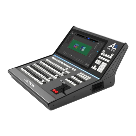
Product overview 2.1 Product profile A6PLUS seamless switchboard, a video processing device developed for LED large screen display systems, adopts the industry's top image processing chips and 12- bit digital image processing to produce real and colorful images. It is mainly used in the field of on-site stage performance control. - Page 8 Available with A8 and A6 400 masters Pure hardware drive operation, dual power supply configuration, reliable and stable operation of equipment Page 5 of 43...
-
Page 9: Product Model
2.3 Product model A6PLUS console Model Configuration A6PLUS Console A6PLUS console and accessories A6 master Model Configuration A6 400-E Input: 8DVI+2HDMI+2DP output: 4DVI host +4DVI standby A6 400-F Input: 4DVI+2HDMI+2DP+2SDI+2VGA output: 4DVI host +4DVI standby A6 400-G Input: 12DVI+2HDMI+2DP output: 4DVI host +4DVI standby A6 400-H Input: 8DVI+4HDMI+4DP+4SDI+4VGA output: 4DVI host +4DVI standby A6 400-I... -
Page 10: Appearance Introduction
Appearance introduction 3.1 Product size Unit: mm Page 7 of 43... -
Page 11: Front Panel
3.2 Front panel 3.2.1 Console lighting The access to the Canon lights, which can be connected to 2 lights, is controlled by the back switch of the console. 3.2.2 Touch screen Single click to control can be carried out through the display screen in the way of touch control, and reasonable adjustment of menu and parameters can be made at the same time for real-time monitoring of the preview screen. -
Page 12: Layer Selection
Note: The next level of operation can only be performed when the destination is "red". The "preview" switching "program" is switched according to the status of the destination. Only the "activated" and "selected" status can be switched, and the "inactivated"... -
Page 13: User-Specified Area
3.2.6 User-specified area display/function keys 3.2.7 Key function Under ASSIGN1, four modes, INPUT, PRESET, AUX1 and AUX2 can be switched, which can be switched by function keys ASSIGN1, ASSIGN2, ASSIGN3, ASSIGN4, are all keys with different functions and can be selected freely ... -
Page 14: Led Light Strip
Each of the 1 to 12 keys of PRESET corresponds to a preset, beyond which the page can be turned down, or 48 presets for one page display can be realized by adjusting the function keys, with a maximum of 132 presets supported ... -
Page 15: Shortcut Function Area
3.2.10 Shortcut function area DEST: to be developed LAYER: layer editing INPUT: input function PRSET: Preset function SCREEN: menu navigation MVR: monitoring function USER KEY: to be developed CUE: to be developed ... - Page 16 INPUT: input function HPOS: move intercept horizontal position VPOS: move to intercept vertical position HSIZE: intercept screen with horizontal size. VSIZE: intercept screen with vertical size RESET: reset interception to default Example: press HPOS, type the value through numeric...
- Page 17 PRSET: Preset function LOCK ALL: lock all presets UNLOCK ALL: unlock all presets LOCK UNLOCK: lock/unlock current preset SAVE PVW: save preview template SAVE PGM: save program template OWEITE FROM PVW: preview template overrides the currently selected preset ...
- Page 18 MVR: monitor calling VP ID: correspond to the ID name of the master, multi- control by one machine, and monitoring output controlled by switching VP MODE 4X1: adjust monitor panel splicing mode to 4HX1V MODE 2X2: adjust monitor panel splicing mode to 2HX2V ...
-
Page 19: Numeric Keyboard Area
3.2.11 Numeric keyboard area MOD PGM: program output synchronous preview screen PANEL LOCK: one-key lock console FREEZE PGM: this feature is used for A8 masters BLACK: this feature is used for A8 masters H&V: horizontal and vertical equal proportion H POS: horizontal start V POS: vertical start H SIZE: horizontal size V SIZE: vertical size For example: the current horizontal window is 960. -
Page 20: Rear Panel
3.3 Rear panel Aviation connector network cable interface LAN1: connect to console master LAN2: function yet to be developed USB interface 5V power supply, external equipment such as console can be upgraded with mouse, keyboard and USB flash drive, and 4 ports can be plugged and played. RS232 bus interface (DEBUG) Equipment debugging interface Power interface... -
Page 21: Front Panel Of Master
3.4 Front panel of master SYSTEM (System Indicator Light) Flashing: indicates that the master is running normally (LINK) link indicator Normally on: indicates that the console is connected to the master DATA (data transfer lamp) Flashing: data is being transferred. (ID) ID indicator light: ID1-7 is the combination of lights 1, 2 and 4, which is always on (if ID: 3 is the combination of lights 1 and 2, which is always on). -
Page 22: Rear Panel Of Master
3.5 Rear panel of master 1. ①-⑥ Input board, corresponding input of 1-24 2. ⑦ Multi-screen preview output panel 3. ⑧ Control panel 4. ⑨-⑩ Output panel for providing video image output 5. Power panel for providing dual power backup power supply Page 19 of 43... -
Page 23: Application Scenarios
Application scenarios Tips: When the equipment is connected, disconnect the power supply first. When accessing the wire, confirm whether the wire interface is damaged. Page 20 of 43... -
Page 24: Equipment Connection
Equipment connection 5.1 Single-machine direct connection Connect the LAN1 of the console and the other end to the master IP/LAN port using the RJ45 specification network cable. After the switch on, the LAN1 light on the console is normally on, and the LINK light on the master is normally on, which means the network has been connected. - Page 25 After the switch on, the LAN1 light on the console is normally on, and the LINK light on the master is normally on, which means the network has been connected. Master IDs (1-7) are sorted from small to large, small is master, large is slave. If the master has the same ID number, please turn off a master and access after changing the ID number.
- Page 26 Figure 4.2 Figure 4.3 A6 (ID=1) is master lock A6 (ID=2) is slave lock Page 23 of 43...
-
Page 27: A6Plus Control Software Description
A6PLUS software instructions 6.1 Menu navigation 1. Menu navigation System: switch the master, input, output, debugging and view Edit: target layer debugging and template storage Settings: adjust console and master customizations, upgrades, Save: save user settings Power off: system soft power off ... -
Page 28: Master Settings
5. Message notification column Prompt operation information and error prompt 6. Destination information column Display the currently added destination output information, and select to delete the destination. 6.1.1 Master settings Input Settings Master Settings Output Settings Parameter Adjustment MVR settings ... - Page 29 1. 4K panel card settings Select 4K interface and set parameters in the adjustment column on the right, as shown in Figure 6.1 Figure 6.1 1. EDID Display the current source type and resolution Select the resolution in the EDID list and apply it, and flash it successfully 2.4K Mode ...
-
Page 30: Monitor Panel Settings
lower-left, and lower-right, respectively corresponding to the four input ports. 2. DVI panel card settings Select the DVI interface, set the parameters in the adjustment column on the right, select the resolution in the EDID list and apply it, and flash it successfully. 3. -
Page 31: Destination Settings
6.1.4 Destination settings Multiple destinations can be added, and each destination can be switched individually 8 outputs, 4 masters and 4 standby, select the output port and click Add Destination. Add output information will be displayed in the destination message bar, and then add successfully, as shown in the following Figure: ... -
Page 32: Layer Editing
6.2 Layer editing 6.2.1 Layer area description 1. Input source list, display the input source, resolution and display status under the current VP. Select the layer to select the input source 2. Destinations are displayed in full screen one after another with multiple destinations at the same time 3. -
Page 33: Function Adjustment
Window size: display the size of the current layer at the destination in numerical manner Window position: display the location of the current layer at the destination in a numeric manner Function display 6.2.2 Function adjustment 1. Once the layer is selected, you can set its window settings ... -
Page 34: Key
6.2.3 KEY Key: subtitle overlay, matting (valid only on D layer), and the matting effect as shown below: Select the D layer to turn on the Key switch, and the upper position of the layer displays the color-buckling character to turn on the color-buckling character ... - Page 35 (RGB: Red 10, green 0, blue Matting red background (RGB: Red 255, green 0, blue Matting white background RGB: (red 255 green 255 blue 255) Matting green background (RGB: Red 0, green 128, blue Matting blue background 255/32 (RGB: Red 0, green 0, blue 255) Key type: brightness key In this mode, that light and dark detail of the screen are removed, specifically in gray...
-
Page 36: Preset
6.2.4 Preset Single click to adjust, enter the preset template to save the page Save Preset From PVW: save preview template Save Preset From PGM: save program template Overwrite From PVW: cover preview template Overwrite From PGM: cover program template ... - Page 37 Clone key is valid for the lower layer of the same destination, the picture position is mirrored and clone cannot be applied to the case where the horizontal position is 1 (e.g. 1W*2H/1W*3H/1W*4H). Example: one LED screen requires horizontal two-port splicing (destination mode is 2W*1H).
-
Page 38: Switch
6.2.6 Switch Switching time Quick switch Fade in and out Switching time: minimum 500 milliseconds and maximum 5 seconds in milliseconds (as shown in Figure 10=1000 milliseconds above) You can set the value by adding or subtracting, or you can input a number through the numeric keypad and press Enter to apply it to match fade-in and fade-out CUT: Quickly switch the preview screen to the program AUTO: The preview screen is faded in and out by setting the switching time... - Page 39 Switching type description: Follow: keep switching. After the preview signal is switched to the program (main output), the preview content remains unchanged. Exchange: alternatively switch, the preview screen and the program screen (main output) are exchanged with each other Page 36 of 43...
-
Page 40: Advanced Setting
6.3.1 Advanced setting Manually adjust key brightness Manually adjust the contrast of the OLED Manually adjust LCD backlight Reverse switch for OLED Front light switch 6.3.2 Backup Local backup: save destination information to console ... -
Page 41: Update
6.3.4 Upgrade The USB flash drive is formatted in FAT32 format Copy the console upgrade program to the root directory of the USB flash drive, insert the USB port of the console, click the upgrade console, restart the console after the upgrade is completed, and check the version to see if the upgrade is successful ... -
Page 42: Case Analysis
Case analysis Client needs: watchout plays the material of the organizer, two channels output two signals horizontally (3840*1080), and one field/lottery signal each, the field screen is 5760*1080, and real-time switching of single-screen/three-screen is required 1. The A6PLUS console is connected with a network cable, and outputs 1-3 (program/program) docking sending cards, and the preview connects the preview display 2. - Page 43 The mode is set to 3W*1H (three output ports are divided into three ones horizontally). The destination output source displays the added destination port, the A6 VP master corresponding to the output port Complete adding destination 3. After setting the destination, activate and select the destination, click to set the corresponding destination number, and then click twice to select the destination as the red light is always on, as shown in the following Figure: 5.
- Page 44 (960*1080)/position (4800.0) Output port 1: open four layers (A/B/C/D) to represent 1A.2B windows Output port 2: since the 2B window spans the output port 1 and the output port 2, the B layer key displayed in the output port 2 has also been occupied if the 2B screen uses the B layer in the output port 1 Output port 3: since the 3C window spans the output port 2 and the output port 3, similarly, the 2B screen has shown that the 3C and 4D of the output port 1 are...
-
Page 45: Troubleshooting
Troubleshooting ▶ During installation or use, problems may be encountered, and users may attempt to find the problem by following these steps. If problems are unable to be found, the users can contact their local distributor. No image is output, and the power indicator light is off ▶... -
Page 46: Warranty
Warranty 12 months from that invoice date of the user's purchase of the machine Non-warranty requirements Failure or damage caused by force majeure (e.g. fire, earthquake) or natural disaster (e.g. lightning strike) Failure or damage caused by other abnormal use reasons such as water immersion, collision, stains or surface scratches after use of the machine ...
Need help?
Do you have a question about the A6 PLUS and is the answer not in the manual?
Questions and answers