Table of Contents
Advertisement
Quick Links
Add: 22F, Block C2, Nanshan Zhiyuan, No.1001 Xueyuan Road,
Nanshan District, Shenzhen, China
Email: freedeo@timewaying.com
Website: www.timewaying.com
Tel: (86) 755-8386 9836
Fax: (86) 755-8386 9896
SHENZHEN TIMEWAYING TECHNOLOGY CO.,LTD.
Passive 3D Cinema System
TURBO SCREEN
Model No.: FD-T05F
User Manual
Attention:Please review this User Manual carefully before installation.
Service Hotline:(86) 400 888 6862
Advertisement
Table of Contents

Summary of Contents for FREEDEO TURBO SCREEN FD-T05F
- Page 1 Passive 3D Cinema System TURBO SCREEN Model No.: FD-T05F Add: 22F, Block C2, Nanshan Zhiyuan, No.1001 Xueyuan Road, Nanshan District, Shenzhen, China Email: freedeo@timewaying.com Website: www.timewaying.com Tel: (86) 755-8386 9836 Fax: (86) 755-8386 9896 User Manual Attention:Please review this User Manual carefully before installation.
-
Page 2: Table Of Contents
Contents 1. System Overview..................1 2. System Features..................2 3. Requirements on Cinema Environment............2 4. Digital Projector Setting................2 5. 3D System Components................3 5.1 Turbo Screen Optical Unit................4 5.2 System Bracket..................5 6. Installation of 3D System................6 6.1 Installation of Cabinet Mount Components..........6 6.2 Installation of Motorized Bracket..............7 6.3 Installation of Lifting Gear and Optical Unit..........8 7. -
Page 3: System Overview
1. System Overview 2. System Features Electrical Features Freedeo Turbo Screen 3D cinema system is especially designed for the cinema application. In cooperation with high quality 3D eyewear, the Power supply: AC 100~240V 50/60 Hz system provides stunning 3D images for small or medium size audiences Sync Input: GPIO (37PIN) or 3D interface (15PIN) on screens up to 20m wide. -
Page 4: D System Components
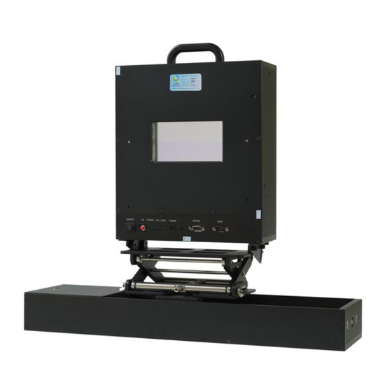
5. System components: 5.1 Turbo Screen Each Turbo Screen system includes following components: Optical Unit, System Bracket, Power Adapter, Power cord Box, SYNC Cable, Motor Driving Signal Cable 282mm 96mm Optical Unit System Bracket Power cord Box Light Incident Window Light Exit Window Figure 5-1-1 Optical Unit Figure 5-1 System Components... - Page 5 5.2 System Components 6. System Installation Each Turbo Screen has a bracket to match with the projector stand. It can 6.1 Install cabinet mount components: adjust height and be used to adjust the Turbo Screen's height, angle, left and right as well as length of cabinet mount components, and fix the components to the front and rear position to best fit the space of the Turbo Screen and projector cabinet with fastener, as shown in Figure 6-1.
- Page 6 6.2 Install Motorized Bracket 6.3 Install lifting gear and optical unit Fix aluminum section (30*60*800mm) to the cabinet mount components Fix lifting gear to the motorized bracket, and then install the optical unit with L shape block, and then install the motorized bracket to the aluminum into the lifting gear, as shown in Figure 6-3.
-
Page 7: System Connection
7. System Connection 7.2 LED status indicators After the connection is completed, turn on the system and digital projector 7.1 System Connection to play 3D movie, check the cables are connected correctly by observing Optical Unit (MOTOR interface)------- Motorized bracket(Motor driving signal interface) the LED status indicators on the front panel, as shown in Figure 7-2. -
Page 8: System Positioning
8. System Positioning 8.2 Height and angle fine adjustment: Turn on the digital projector and load cross calibration pattern from the 8.1 Set the initial position of optical unit: projector, briefly adjust position of up and down, left and right, center the power on optical unit and the digital projector to play 3D movie, the position of the pattern on the light exit window, as shown in Figure 8-2. -
Page 9: System Optical Alignment
9. System Optical Alignment Position projector lens focuses on the screen, fine adjust upper beam and lower beam position to coincide the cross calibration pattern align with Clear 3D imagery synthesis depending on the upper and lower beam image middle beam, when finish, adjust the size of middle beam image to center position and the middle beam image size. -
Page 10: Cautions
Do not touch the light incident window and light exit window directly with your hands. Power off the system when it is not in use. Please use Freedeo polarized 3D glasses when watching 3D movies, to avoid ghosting and color cast problems. ※Please operate under the guidance of professional personage.
Need help?
Do you have a question about the TURBO SCREEN FD-T05F and is the answer not in the manual?
Questions and answers