Table of Contents
Advertisement
Quick Links
Advertisement
Table of Contents

Summary of Contents for FUSHENGTEK Technology WG-7302-E38/J19
- Page 1 WG-7302 WG-7302User’sGuide WG-7302 User’s Guide...
-
Page 2: Table Of Contents
Page 2 WG-7302 Table of Contents » Table of Contents « 1 Introduction ........................8 Ordering Information ......................8 2 Installation Procedure ......................9 2.1 Installing the Board ..............................9 2.2 Requirements IEC60950 ............................10 3 System Specifications ....................... 11 3.1 Component main data ............................ - Page 3 Page 3 WG-7302 Table of Contents 7.7 Serial COM1 – COM6 Ports ..........................25 7.8 Audio Connector(AUDIO) ........................... 26 7.9 GPIO Connector (GPIO) ............................27 7.10 LCD Power (LCD_PWR) ........................... 27 7.11 Clear CMOS (JCM1) ............................27 7.12 Power Button and Reset (PWR) .......................... 27 7.13 “Always On”...
- Page 4 Page 4 WG-7302 Table of Contents Appendix D: Dimensional drawing ..................60 WG-7302 User’s Guide...
- Page 5 Brand and product names are trademarks or registered trademarks of their respective owners Disclaimer FUSHENGTEK Technology reserves the right to make changes without notice to any product, including circuits and/or software described or contained in this manual in order to improve design and/or performance.
- Page 6 Warranty FUSHENGTEK Technology warrants its products to be free from defects in material and workmanship during the warranty period. If a product proves to be defective in material or workmanship during the warranty period FUSHENGTEK Technology will, at its sole option, repair or replace the product with a similar product.
- Page 7 FUSHENGTEK Technology Technical Support and Services If you have questions about installing or using your FUSHENGTEK Technology Product, then please notice that you will find many answers in this Users Guide. To obtain support please contact your local Distributor or Field Application Engineer (FAE).
-
Page 8: Introduction
Document Details 1 Introduction This manual describes theWG-7302 boards made by FUSHENGTEK Technology. In this manual the boards will also be denoted WG-7302-E38/J19. The WG-7302 boards are based on Intel Atom E38xx/J19SoC (System on Chip) “Intel Bay Trail” and will be available in three versions. -
Page 9: Installation Procedure
Page 9 WG-7302 Document Details 2 Installation Procedure 2.1 Installing the Board To get the board running follow these steps. If the board shipped from FUSHENGTEK has already components like RAM and CPU cooler mounted, then relevant steps below can be skipped. 1. -
Page 10: Requirements Iec60950
Page 10 WG-7302 Document Details 8. Mounting the board in chassis Warning: When mounting the board to chassis etc. please notice that the board contains components on both sides of the PCB which can easily be damaged if board is handled without reasonable care. A damaged component can result in malfunction or no function at all. -
Page 11: System Specifications
Page 11 WG-7302 Document Details 3 System Specifications 3.1 Component main data Technical Information Form Factor 3.5" board Atom™ E38xx/J1900 SoC (2 or 4 cores) , Low power 5-10W TDP ® Intel Supports: Atom™ E3805 Single Core 1.33GHz3W ® Intel Atom™... -
Page 12: System Overview
Page 12 WG-7302 Document Details 3.2 System overview The block diagram below shows the architecture and main components of theWG-7302. The key component on the board is the Intel® Atom E38xx SoC (Bay Trail). 2x HDMI CH7511B LVDS 18/24 mSATA (mPCIe) SO-DIMM Memory 1066/1333MHz mPCIe Baytrail... -
Page 13: Connector Locations
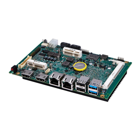
Page 13 WG-7302 Document Details 4 Connector Locations 4.1 WG-7302 – front side E38XX/J19XX SPI flash WG-7302 User’s Guide... -
Page 14: Wg-7302- Back Side
Page 14 WG-7302 Document Details 4.2 WG-7302 – back side Always On SATA Power mPCIe(3G or Wi-Fi) (Pin 1-2 ON, Pin 2-3 NC,) Vin Ext. SATA1 Audio Pin 2-3 Power On Pin 1-2 Reset COM_SEL SODIMM COM (1-6) GPIO LVDS or eDP mSATA mPCIe LCD Power Button... -
Page 15: Connector Definitions
Page 15 WG-7302 Document Details 5 Connector Definitions The following sections provide pin definitions and detailed description of all on-board connectors. The connector definitions follow the following notation: Column name Description Shows the pin-numbers in the connector. The graphical layout of the connector definition tables is made similar to the physical connectors. -
Page 16: Io-Area Connectors
Page 16 WG-7302 Document Details 6 IO-Area Connectors 6.1 HDMI Connectors (HDMI1, HDMI2) The HDMI® interface is available through the standard 19 pin Type A HDMI® connector Signal Description Type TMDS2+ TMDS data 2 (positive) DSO-3.3 Ground TMDS2- TMDS data 2 (negative) DSO-3.3 TMDS1+ TMDS data 1(positive) - Page 17 Page 17 WG-7302 Document Details The signals for the Ethernet ports are as follows: Signal Description MDI[0]+ / MDI[0]- In MDI mode, this is the first pair in 1000Base-T, i.e. the BI_DA+/- pair, and is the transmit pair in 10Base-T and 100Base-TX. In MDI crossover mode, this pair acts as the BI_DB+/- pair, and is the receive pair in 10Base-T and 100Base-TX.
-
Page 18: Usb Connectors (Io Area)
Page 18 WG-7302 Document Details 6.3 USB Connectors (IO Area) The WG-7302B board contains support for 1 USB3.0/2.0 port (Lower USB port, USB1)and3 USB2.0 port (USB2, USB3, USB4) in the IO area. USB 2.0 ports allowing data transfers up to 480Mb/s. The USB 3.0 port allowing data transfers up to 5Gb/s. (Two internal USB ports are available via internal 8-pin connectors) For USB2.0 cabling it is required to use only High Speed USB cable, specified in USB2.0 standard: For USB3.0 cabling it is required to use only High Speed USB cable, specified in USB3.0 standard:... -
Page 19: Dc Power Jack Connector (Vin Ext.)
Page 19 WG-7302 Document Details USB Ports 1 and 2 are mounted together, USB2 (USB2.0) on top of the USB1 (USB3.0/USB2.0). Note Type Signal Signal Type Note USB2- USB2+ 5V/SB5V USB1- USB1+ 5V/SB5V RX0- TX0+ RX0+ TX0- Note 1: In order to meet the requirements of USB standard, the 5V input supply must be at least 5.00V Signal Description USBn+ USBn-... -
Page 20: Internal Connectors
Page 20 WG-7302 Document Details 7 Internal Connectors 7.1 Power Connector (J1.) Header Signal Min. Typ. Max. Units +9.0 +12.0 +24.0 Power +9.0 +12.0 +24.0 Power Maximum allowed current on each pin is 5A. Available cable kit: Power Cable 7.2 Internal SATA Power Connector (SATA_PWR.) Header Signal Description... -
Page 21: Sata (Serial Ata) Disk Interface (Sata1)
Page 21 WG-7302 Document Details 7.3 SATA (Serial ATA) Disk interface The WG-7302’s Support SATA 2.0 standard. Sata connector pinning: Signal Type Ioh/Iol Note SATA* TX+ SATA* TX- SATA* RX- SATA* RX+ Signal Description SATA* RX+ / RX- Host transmitter differential signal pair SATA* TX+ / TX- Host receiver differential signal pair Available cable kit:... -
Page 22: Lvds Flat Panel Connector (J8)
Page 22 WG-7302 Document Details 7.4 LVDS Flat Panel Connector (J8) The LVDS and eDP connector is based on 40 pole connector. The Connector reserved to automatically adjust the screen brightness ALS (Ambient Lightsensor) InterfaceforeDP (Supported on win8 or win 8.1system). Note Type Signal... -
Page 23: Analog Connector (Vga)
Page 23 WG-7302 Document Details Notes: Windows API will be available to operate the BKLTCTL signal. Some Inverters have a limited voltage range 0- 2.5V for this signal: If voltage is > 2.5V the Inverter might latch up. Some Inverters generates noise on the BKLTCTL signal, causing the LVDS transmission to fail (corrupted picture on the display). -
Page 24: Usb Connectors (Usb2 And Usb3)
Page 24 WG-7302 Document Details 7.6 USB Connectors (USB2 and USB3) The WG-7302B support two internal USB 2.0 ports (USB5 and USB6) allowing data transfers up to 480Mb/s. Legacy Keyboard/Mouse and wakeup from sleep states are supported. Over-current detection on all fourteen USB ports is supported. -
Page 25: Serial Com1 - Com6 Ports
Page 25 WG-7302 Document Details 7.7 Serial COM1 – COM6 Ports 4X RS232 and 2X232/422/485 serial ports are available on the WG-7302. Description Type Signal Signal Type Description Serial number RS232 signal RS_232_A_RX RS_232_A_TX RS232 signal COM1 RS232 signal RS_232_B_RX RS_232_B_TX RS232 signal COM2... -
Page 26: Audio Connector(Audio)
Page 26 WG-7302 Document Details 7.8 Audio Connector(AUDIO) The on-board Audio circuit implements High Definition Audio with UAA (Universal Audio Architecture), featuring 24-bit stereo DAC and 20-bit stereo ADCs. Description Description Type Signal Signal Type Line-out right Line-out left Microphone Mic right Mic left Microphone... -
Page 27: Gpio Connector (Gpio)
Page 27 WG-7302 Document Details 7.9 GPIO Connector (GPIO) PullUP Ioh/ Type Signal Signal Type Ioh/ PullUP 3.3V 10k ohm GPIO0 GPIO1 10k ohm 10k ohm GPIO2 GPIO3 10k ohm 10k ohm GPIO4 GPIO5 10k ohm 10k ohm GPIO6 GPIO7 10k ohm 11 12 3.3V... -
Page 28: Always On" (Auto_Btn)
Page 28 WG-7302 Document Details 7.13 “Always On” (AUTO_BTN) The “Always On” can be used to implement hardware controlled always ON by jumper. When “Always On” is selected, the board will power up automatically when power is connected. The board can still be shut down by PWRBTN_IN# (power button in) activation (via PWR). AUTO_BTN Description pin1-2... -
Page 29: Slot Connectors (Mpcie, Msata)
Page 29 WG-7302 Document Details 8 Slot Connectors (mPCIe, mSATA) 8.1 mPCIe or mSATA slot The mSATA port support mPCIe, mSATA and Debug module. (No USB is included). Note Type Signal Signal Type Note WAKE# +3.3V Debug signal Debug signal +1.5V CLKREQ# LEDG... -
Page 30: Mpcie Slot
Page 30 WG-7302 Document Details 8.2 mPCIe slot The MPCIE port support mPCIe. (USB is included) Note Type Signal Signal Type Note WAKE# +3.3V +1.5V CLKREQ# PWR GND CLKN CLKP PWR GND PWR GND RST# PCIE_RX_DN +3.3V PCIE_RX_DP PWR GND +1.5V PWR GND SMB_CLK... -
Page 31: Bios
Page 31 WG-7302 Document Details 9 BIOS The BIOS Setup is used to view and configure BIOS settings for the board. The BIOS Setup is accessed by pressing the <Del>-key (<F2>-key on BIOS version v.16 or below) after the Power-On Self-Test (POST) memory test begins and before the operating system boot begins. -
Page 32: Advanced
Page 32 WG-7302 Document Details 9.2 Advanced Function Option Description ACPI Settings The ACPI Configuration Page CPU Configuration The CPU Configuration Page OS Selection The OS Select Page IDE Configuration The IDE Configuration Page CSM Configuration The CSM Configuration Page USB Configuration The USB Configuration Page SIO Configuration... -
Page 33: Acpi Settings
Page 33 WG-7302 Document Details 9.2.1 ACPI Settings Function Option Description Enable ACPI Auto Conf Disabled Enable or Disable BIOS ACPI Auto Enabled Configuration. Enable Hibernation Disabled Enable or Disable System ability to Hibernate(OS/S4 Sleep State).This option ... -
Page 34: Cpu Configuration
Page 34 WG-7302 Document Details 9.2.2 CPU Configuration Function Option Description Socket 0 CPU Information Show socket 0 CPU information. Number of cores to enable in each Active Processor core processor package. Limit CPUID Maximum Disabled Disable for windows XP. ... -
Page 35: Os Selection
Page 35 WG-7302 Document Details 9.2.3 OS Selection Function Option Description OS Selection Windows 8.X OS Selection Windows 7 WG-7302 User’s Guide... -
Page 36: Ide Configuration
Page 36 WG-7302 Document Details 9.2.4 IDE Configuration Function Option Description Serial-ATA (SATA) Enable / Disable Serial-ATA Disabled Enabled SATA Mode Select IDE / AHCI IDE mode AHCI mode Serial-ATA Port 0 Enable / Disable Serial-ATA Port 0 Disabled ... -
Page 37: Csm Configuration
Page 37 WG-7302 Document Details 9.2.5 CSM Configuration Function Option Description CSM Support Enbale / Disbale CSM Support. Disabled Enabled GateA20 Active This option is useful when any RT code is Upon Request executed above 1MB. Always Option ROM Messages ... -
Page 38: Usb Configuration
Page 38 WG-7302 Document Details 9.2.6 USB Configuration Function Option Description Legacy USB Support Disabled Enables or Disable Legacy USB support. Auto option Enabled disables legacy support if no USB devices are Auto connected. DISABLE option will keep USB devices available only for EFI applications. -
Page 39: Sio Configuration
Page 39 WG-7302 Document Details 9.2.7 SIO Configuration Function Option Description Serial Port 1 Enable / Disable Serial Port 1 Serial Port 2 Enable / Disable Serial Port 2 Serial Port 3 Enable / Disable Serial Port 3 Serial Port 4 Enable / Disable Serial Port 4 Serial Port 5 Enable / Disable Serial Port 5... - Page 40 Page 40 WG-7302 Document Details 9.2.7.1 Serial Port 1 Function Option Description Use This Device Disabled Enable or Disable this Logical Devcie. Enabled Use Automatic Settings Allows user to change Device’s Possible Io=3F8h;IRQ4;DMA; Resource settings. New settings will ...
- Page 41 Page 41 WG-7302 Document Details 9.2.7.2 Serial Port 2 Function Option Description Use This Device Disabled Enable or Disable this Logical Enabled Devcie. Possible Use Automatic Settings Allows user change Device’s Resource settings. Io=3F8h;IRQ4;DMA; Io=3F8h;IRQ3,4,5,7,9,10, New settings will be reflected 11,12,DMA;...
- Page 42 Page 42 WG-7302 Document Details 9.2.7.3 Serial Port 3 Function Option Description Use This Device Disabled Enable or Disable this Logical Enabled Devcie. Possible Use Automatic Settings Allows user change Device’s Resource settings. Io=3F8h;IRQ4;DMA; Io=3F8h;IRQ3,4,5,7,9,10, New settings will be reflected 11,12,DMA;...
- Page 43 Page 43 WG-7302 Document Details 9.2.7.4 Serial Port 4 Function Option Description Use This Device Disabled Enable or Disable this Logical Enabled Devcie. Possible Use Automatic Settings Allows user change Device’s Resource settings. Io=3F8h;IRQ4;DMA; Io=3F8h;IRQ3,4,5,7,9,10, New settings will be reflected 11,12,DMA;...
- Page 44 Page 44 WG-7302 Document Details 9.2.7.5 Serial Port 5 Function Option Description Use This Device Disabled Enable or Disable this Logical Enabled Devcie. Possible Use Automatic Settings Allows user change Device’s Resource settings. Io=3F8h;IRQ4;DMA; Io=3F8h;IRQ3,4,5,7,9,10, New settings will be reflected 11,12,DMA;...
-
Page 45: Chipset
Page 45 WG-7302 Document Details 9.3 Chipset Function Option Description North Bridge North Bridge Parameters South Bridge South Bridge Parameters WG-7302 User’s Guide... -
Page 46: North Bridge
Page 46 WG-7302 Document Details 9.3.1 North Bridge Function Option Description Config Intel IGD Settings Intel IGD Configuration Graphics Power Management Graphics Power Management Control Options Control LCD Settings LCD Control WG-7302 User’s Guide... - Page 47 Page 47 WG-7302 Document Details 9.3.1 .1 Intel IGD Configuration Function Option Description Integrated Graphics D Enable : Enable Integrated Graphics Device Disabled (IGD) when selected as the primary video Enabled Adaptor. Disable: Always disable IGD IGD Turbo Enable ...
- Page 48 Page 48 WG-7302 Document Details DOP CG Enable / Disable DOP Clock Gating Disabled Enabled GTT Size Select the GTT Size IGD Thermal Enable / Disable IGD Thermal Disabled Enabled Spread spectrum clock ...
- Page 49 Page 49 WG-7302 Document Details 9.3.1 .3 LCD Control Function Option Description LCD Panel Type VBIOS Default Select LCD panel used by 640 x 480 Internal Graphics Device by 800 x 600 selecting the appropriate setup 1024 x 600 item.
-
Page 50: South Bridge
Page 50 WG-7302 Document Details 9.3.2 South Bridge Function Option Description Azalia HD Audio Azalia HD Audio Options USB Configuration USB Configuration Settings WG-7302 User’s Guide... - Page 51 Page 51 WG-7302 Document Details 9.3.2 .1 Azalia HD Audio Function Option Description Audio Configuration Control Detection of the Azalia device. Disabled Disabled=Azalia will be unconditionally Enabled disabled. Enabled=Azalia will unconditionally Enabled. Auto=Azalia will be enabled if. Azalia HDMI Codec ...
- Page 52 Page 52 WG-7302 Document Details 9.3.2 .2 USB Configuration Function Option Description XHCI Mode Enable / Disable USB 3.0 Mode Disabled Enable USB 2.0(EHCI) Support Control the USB EHCI(USB 2.0) Disabled functions. One EHCI controller must Enable always be enabled USB Per Port Control...
-
Page 53: Security
Page 53 WG-7302 Document Details 9.4 Security Function Option Description Administrator password Set Administrator password User password Set User password WG-7302 User’s Guide... -
Page 54: Boot
Page 54 WG-7302 Document Details 9.5 Boot Function Option Description Setup Prompt Timeout Number of seconds to wait for setup activation key.65535(OxFFFF) means indefinite waiting Select the Keyboard Numlock BootupNumLock State state Disabled Enables or disables Quiet Boot Quiet Boot ... -
Page 55: Save & Exit
Page 55 WG-7302 Document Details 9.6 Save & Exit Function Option Description Save Changes and Exit Exit system setup after saving the changes Discard Changes and Exit Exit system setup without saving any changes Save Changes and Reset Reset the system after saving the changes Discard Changes and Reset Reset the system without saving any changes Save Changes... -
Page 56: Appendix A:customized
Page 56 WG-7302 Document Details Appendix A:Customized 1 Display combinations The WG-7302 provides four display interfaces, but the chipset supports up to Dualdisplay.The following table shows a combination of the display. Note: Different Display require differentBill of Materials, so please let us know your needs before you purchase. Default HDMI0 and HDMI1 is available. -
Page 57: Appendix B:gpio Sample Code
Page 57 WG-7302 Document Details Appendix B:GPIO Sample Code The WG-7302 provideseightGeneral Purpose I/O Ports. Each of them that can be individually programmed as input or output.The GPIO register be accessed though IO access mode. GPIO Group Select Register BaseAddress: 0x298 Offset: 0x00 Attribute: R/W Size: 8 bits... - Page 58 Page 58 WG-7302 Document Details Sample Code MOV DX, 298H MOV AL, 04H OUT DX, AL :Select GPIO Group4 MOV DX, 299H MOV AL, 0FFH OUT DX, AL :Set GPIO 0 ~ 7 as Input MOV DX, 29AH IN AL,DX :Read GPIO 0 ~ 7 input status MOV DX,299H MOV AL, 00H...
-
Page 59: Appendix C:watchdog Sample Code
Page 59 WG-7302 Document Details Appendix C:WatchDog Sample Code The WG-7302 provides a Watchdog Timer . The Watchdog Time consists of an 8-bit programable time-out counter and a control and status register.The units of Watchdog Timer counter can be suppport second/minute.When Watchdog Timer time-outevent is occcurring,The system will be perform Reset.The Watchdog Timer's register be accessed though IO access mode. - Page 60 Page 60 WG-7302 Document Details Appendix D: Dimensional drawing WG-7302 User’s Guide...
Need help?
Do you have a question about the WG-7302-E38/J19 and is the answer not in the manual?
Questions and answers