Table of Contents
Advertisement
Quick Links
Ring Light Kit
Ring Light Module
Battery Module
取扱説明書
Instruction Manual
こ の 度 は 、 ダ イ ブ エ ク ス ト リ ー ム 製 品 を お 買 い 上 げ い た だ き 、
誠 に あ り が と う ご ざ い ま す 。
本製品をご使用の前に、この取扱説明書をよくお読みください。
また、 保証書は別紙で同梱しておりますので大切に保管してください。
Thank you for purchasing an DiveExtreme product.
Before using this product, please read this Instruction Manual
thoroughly.
Advertisement
Chapters
Table of Contents

Summary of Contents for DiveExtreme DL2001
- Page 1 こ の 度 は 、 ダ イ ブ エ ク ス ト リ ー ム 製 品 を お 買 い 上 げ い た だ き 、 誠 に あ り が と う ご ざ い ま す 。 本製品をご使用の前に、この取扱説明書をよくお読みください。 また、 保証書は別紙で同梱しておりますので大切に保管してください。 Thank you for purchasing an DiveExtreme product. Before using this product, please read this Instruction Manual thoroughly.
- Page 2 製品の特徴 • フラッシュモード搭載 (2 段階調光) DL2001リングライトキッ トはオリンパス TG シリーズに最適設計され ・TG シリーズの内蔵フラッシュ位置に合わせて受光センサーを配置 た小型軽量リングライトです。 しているため、光ファイバーなしでフラッシュモードが動作します。 • TG シリーズに最適化された光学設計 • 直感的な操作が可能な回転モードダイアル ・ リング部の薄型化とダイレクトセッ トにより ※ 最短照射距離 3.5cm。 ・マグネット式回転モードダイヤル。ボタンレス構造による高い防水 ・小型でも水中での 4 隅のケラレはありません。 性能。モードが後方から視認でき、直感的な操作を可能にします。 ・最大 1200lm のムラのない均一なリング光。多様な撮影状況に対 応できる5 段階調光+フラッシュモード (2 段階調光) 。 • モジュール構造 ・色温度:5000K / 演色性:Ra80 以上...
-
Page 3: Table Of Contents
はじめに 目次 • 本書の内容を無断で複写することは、個人としてご利用にな 安全上のご注意 ........... 4 る場合を除き禁止されています。 同梱品一覧 ............6 • 本製品の内容については、予告無しに変更することがあります。 各部位名称 ............8 • 本製品の不適切な使用により、損害が生じた場合第三者からの ライトモジュールキャップの取り外しと取り付け方法 ..10 いかなる請求に関し、当社では一切の責任を負いません。 バッテリーモジュールキャップの取り外しと取り付け方法 ... 11 • 本製品の故障、当社指定外の第三者による分解、修理、改造 防水仕様について ..........12 その 他の理由により生じた損害に関し、当社では一切の責任 ご使用前のメンテナンス ........14 を負いません。 本体を充電する ..........16 ご使用方法 ............17 ※本製品には、電子回路や充電式リチウムイオン電池が組込まれ... -
Page 4: 安全上のご注意
安全上のご注意 ■安全上のご注意 • 分解・改造をしない。 • 製品を正しく安全にお使いいただくために、ご使 用の前には • モジュールを単体で水中に持ち込まない。 この 「安全上のご注意」を必ずお読みください。 • この 「安全上のご注意」には安全のための重要な情報が記載 ※ライトモジュールとバッテリーモジュールは 水中での接続・ されていますので、必ず守ってください。 取り外しはできません。 • 以下の表示の区分は、記載内容 を守らず、誤った使い方をし • 火の中に入れたり、オーブンで加熱しない。 た場合に生じる危害や損害の程度を説明しています。 • 高温の場所で使用や放置をしない。 • 乳幼児の手の届く場所に置かない。 死亡または重傷を負う危険性が大きいと想定 される内容です。 死亡または重傷を負う可能性が想定される内 • 人の目に向けて点灯させない。 容です。 • バッテリーモジュール USB コ ネクタを、 金 属 のピンなど で 損害を負うことや、物的損害発生が想定される... - Page 5 • 家庭用電 源や AC アダプターは、プラグを根元まで確実に差 の構造上、点灯する場合があるため、留め金に強力な磁石を使 し込む。 用しているバッグに本製品入れるときは留め金付近のポケットな • 本体を振り回したり投げたりしない。 どには入れない。 • マグネットを使用したダイビング用器材、水中撮影用アクセサ リーなどと組合せて使用しない。 • 陸上では長時間 (5 分以上)点灯させない。 • 床や机などの上に、光源を下向きにした状態で点灯させない。 • 異臭、異常音、変形、煙が出るなどの異常が生じた場合は、直 ちに使用を中止する。 • 水中にエントリーする際に、本製品を持ったまま飛び込まない。 • モジュール接続時は、O リングの点検を行う。 • モジュールの接続は、正しく行う。 • ライトモジュール/バッテリーモジュールの保管時は、付属のモ ジュールキャップを装着する。 • 長期間使用しない場合は、 AC アダプターをコンセントから抜く。 • 本製品はスイッチにマグネットを使用しているので時計、電子機 器等、マグネットにより影響を受ける製品をそばに置かない。 • マグネットを使用した製品の近くに本製品を近づけると、製品...
-
Page 6: 同梱品一覧
コネクターキャップセット DE シリコングリス DL-LMC02 DL-FCC01 DL-SG01 O リングに添付します。 P .15 参照 リングライトモジュール本体 DE 六角レンチ、 固定ボルトセット DE フロントプロテクター DE メンテナン用オープナー DL-HX01 (DL2001) DL-MO02 DL-FP01 プロテクター (ハウジング) の DE ライトモジュールキャップ 取り付けに使用します。 メンテナンスナットを取り外すときに DL-LMC02 予備として付属。P .29 参照 P .20 参照 使用します。P .30 参照... - Page 7 ■ バッテリーモジュール DL-BM01 バッテリーモジュール本体 DE バッテリーモジュール キャップ DE USB接続ケーブル (TYPE-C) DL-BMC01 DL-UCC01 ※ USB 対応の AC アダプターは、パソコン・携帯電話端末などの普 及により多くの方が所持されているため、できるだけ無駄をなくし たいという観点から、本製品に USB 対応の AC アダプターは付属 されていません。...
-
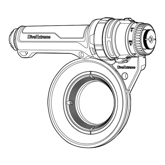
Page 8: 各部位名称
各部位名称 ■リングライトモジュール DL-LM01 O リング ( 赤 ) ライトモジュールキャップ モードロックレバー ( 赤 ) インジケーター ※ライトモジュールキャップに防 ライトモジュールとバッテリー 電 源ON、 バッテリー残量、 水機能はありません。 エラー発生を表示します。 モジュールの接続部を防水します。 フラッシュモード受光口 モードダイヤル メンテナンスナット 電気接点 (4カ所 ) 光ファイバー 水などに濡れた場合は、 き コネクターキャップ (1穴 ) れいに拭き取っ て ください。 ワイヤレスフラッシュ バッテリーロックレバー ( 黒 ) 受光口... - Page 9 各部位名称 ■バッテリーモジュール DL-BM01 アクセサリー ロックリング ( 黒 ) 取り付け穴 ストラップ用穴 拡張アクセサリー 取り付けネジ USB コネクタ 充電表示ランプ バッテリーモジュールキャップ ※バッテリーモジュールキャップに オーバープレッシャーバルブ 防水機能はありません。 電気接点 (4カ所) < 正面 >...
-
Page 10: ライトモジュールキャップの取り外しと取り付け方法
ライトモジュールキャップの取り外しと取り付け方法 ■取り外し ■取り付け 本体底面のバッテリーロックレバー (黒) 方向へ引きながら ①ライトモジュールの指標 ( 白 ) とキャップの を合わせて キャッ プを反時計方向に回して引き抜きます。 キャッ プを差し込みます 。 ②キャッ プを 方向にカチッと音がするまで時計方向に回し ます 。 指標 (白) バッテリーロックレバー (黒)... -
Page 11: バッテリーモジュールキャップの取り外しと取り付け方法
バッテリーモジュールキャップの取り外しと取り付け方法 ■取り外し ■取り付け ①ロックリングを時計方向に止まるまで回します。 ①ロックリングをキャップの指標と が合うまで時計方向 に回します。 ②キャップの指標と を合せてキャップをバッテリーモ ②キャップを引き抜きます。 ジュールに押し込みます。 ③キャップを軽く押さえつけながらロックリングを反時計方向 に回します。 指標 ロックリング... -
Page 12: 防水仕様について
防水仕様について ■二重の防水構造 • バッテリーモジュール内部への浸水を防ぐために、2 つの O リ O リング ( 赤 ) ング (赤)が装着されています。さらに電気接点への浸水を防ぐ 為に防滴パッキン (生活防水レベル IPX6)が施されています。 • 各モジュールが接続された状態 (水中で使用する状態)での、 耐水深は 100m (IPX8) です。100m 以上の水深では使用でき ません。またこの防水は、お客様のメンテナンスにより保たれ 防滴パッキン ます。万一、 本体が水漏れした場合、 内部の保護回路が作動し、 一時的に電源が入らなくなります。 ※モジュールを各々取り外した状態での防水仕様はありません。 ※ USB 接続ケーブルは防水仕様ではありませんので、水に濡ら さないようにご注意ください。... - Page 13 O リング溝 本製品の耐水深 100m 防水は、ライトモジュールの O リングお よび O リング溝とバッテリーモジュール の O リング当て付け面 が密着することによって機能を保っています。 ご購入直後でも水中で使用する前には必ず、以下のメンテナンス を行ってください。 • O リングは消耗品ですので目安として 1 年に一回は交換してく ださい。以下に示す異常があった場合は、必ず新品の専用 O リング (DL-OS02)と交換してください。 • グリスは必ず、専用シリコングリスを使ってください。 • O リン グにヒビ、 キズ、 へ こみなどの 異 常 が あった場 合 は、 必ず新品の専用...
-
Page 14: ご使用前のメンテナンス
ご使用前のメンテナンス 3. O リング溝を綿棒などできれいに清掃します。 1. 防水用 O リング (赤) 2個を取り外します。下図のように O リ ングを指でつまみながら押し出すことにより取り外しやすくな ります。 2. 取り外した O リングにゴミや異物などが付いていないか、キ ズやヒビ割れが無いか確認します。 ※もし、異常がある場合は新品の O リング (DL-OS02)に交換 してください。... - Page 15 4. O リングに専用シリコングリスを塗布します。 5. O リングと O リング溝にごみの付着がないことを入念に確認 してから取り付けます。 ※取り付ける際は、O リングを過度に引っ張ったり、キズを付け ないように注意してください。 米粒半分くらいを 手にとります。 水漏れの可能性がある付着物、キズの一例 (髪の毛、繊維ゴミ、塩の結晶等) 全体に薄く塗ります...
-
Page 16: 本体を充電する
本体を充電する USB 対応の AC アダプターは、パソコン・携帯電話端末など の普及により多くの方が所持されているため、できるだけ無 駄をなくしたいという観点から、本製品に USB 対応の AC ア ダプターは付属されていません。 ※出力が DC5V/1A 以上の AC アダプターをご使用ください。 1. USB 接 続 ケ ーブ ル の 小 さ い コ ネ ク タ ー (Type-C 側 ) を バッテリーモジュールの USB コネクタに差し込みます。※ Type-C コネクターはどちらの方向でも差しこめます。... -
Page 17: ご使用方法
ご使用方法 ライトモジュールとバッテリーモジュールの接続 ・ 取り外し方法です。 : 不用意な点灯から目を保護するために、ライトモ ジュールとバッテリーモジュールを接 続する前に は必ずライトモジュールのモードダイヤルを OFF/ LOCK 位置に合せてください。 指標 (白) ■接続 1. ライトモジュールに装着されているライトモジュールキャッ O リング プとバッテリーモジュールに装着されているバッテリーモ ジュールキャップを取り外します。※ P.11 参照 ロックリング ※ライト/バッテリーモジュール単体での保管時には、必ずこの ライト/バッテリーモジュールキャッ プを取り付けて ください。 CLOSE 2. ライトモジュールに O リングがついていることを確認してく ださい。 3. バッテリーモジュールのロックリングを時計回りに止まるま で回します。ライトモジュールの指標 (白)を を合 わせ止まるまで押し込みます。 4. ロックリングを図の方向に回し、... - Page 18 ■取り外し ライトモジュール底面のバッテリーロックレバー (黒)を の方 向に引きながら、バッテリーモジュールのロックリングを の方向に止まるまで回して引き抜きます。バッテリーモジュール 内部への水滴落下を防ぐため、図の方向に引き抜いてください。 ロックリング バッテリーロックレバー ( 黒 )
-
Page 19: プロテクター (ハウジング)への取り付け・取り外し方法
プロテクター (ハウジング)への取り付け・取り外し方法 ポジションコレクティング機構 (特許出願中) ポジションコレクティング機構:ねじ込みだけの固定方法ではネジを 止めるまで締めつけると、どこで止まるかがわからなく、リングライ トをハウジングに対して水平の位置に固定できませんが、ポジション コレクティング機構の位置決めリングと位置決めボルトにより、リン グライトをハウジングに対して水平に固定することができます。 ネジにねじ込んだだけでは ポジションコレクティング機構により水平位置に どこで止まるかわからない。 固定できます。... - Page 20 ■ プロテクター (ハウジング)への取り付け 【位置決めリングを本体に密着させる】 ① 付属の六 角レン チでリン グライト本体 の 位 置 決 めボ ルト (4カ所) を緩めて、位置決めリングをリングライト本体に密 着させます。位置決めボルトは小さいので紛失しないように 注意してください。予備のボルト (4 個)が付属しています のでご使用時には携行してください。 密着させる 密着させる 位置決めボルト (4カ所) 位置決めリング...
- Page 21 【リングライトをねじ込む】 【リングライトを水平に合わせる】 ② 本体の M52 ネジをハウジングの M52 ネジに時計方向にねじ込み、 ③ 本体を反時計方向に回転させて図の位置で止めてください。 止まるまで回します。 ※必要以上の力で回さないでください。...
- Page 22 【固定ボルトを締める (4カ所) 】 ④ 付属の六角レンチで①で緩めた位置決めボルト (4 カ所) を止まる まで締めつけます。この調整で固定位置を決めることにより、リ ングライトをハウジングから着脱しても同じ位置に固定されます。 繰り返し着脱後に位置がずれてしまった場合は、上記の手順にて 再度調整します。 ※必要以上の力で回さないでください。 ...
- Page 23 ■ プロテクター (ハウジング) からの取り外し リングライトを反時計方向に回して取り外します。 振動等による位置決めボルトの脱落、紛失を防ぐために取外し後 ご使用後は塩がみを防ぐため、リングライトをハウジングから はリアキャップを取り付けてください。 取り外してください。取り外しが固い場合は位置決めボルトを緩 ※位置決めリングのガタがなくなるまで締めつけてください。 めて本体を回してください。 ※破損の恐れがありますのでバッテリーモジュールを掴んで回さ ないでください。 リアキャッ プ...
-
Page 24: 本体の操作方法
本体の操作方法 ■ 光量別連続点灯時間 モードダイヤルを下記の位置に回転させてモード/光量を選択します。 モードダイヤル指標が OFF/ LOCK の位置の時はモードロックレバー モード ライトモード フラッシュモード (赤)を矢印の方向に押しながら回してください。 調光 :移動、運搬時にライトを使用しない時はモードダイ 100lm 200lm 300lm 600lm 1200lm 300lm 600lm ヤルを OFF / LOCK 位置に合わせて不用意に点灯 連続点灯 しないようにしてください。 480 分 360 分 240 分 120 分 60 分 時間 モードロックレバー (赤) ■... - Page 25 ■ ライトモード (5 段階調光) モードダイヤルを 1 (暗) 〜 5 (明)に合わせて光量を調整します。 操作する場合はカメラの内蔵フラッシュを OFF にしてください。 ■ フラッシュモード (2 段階調光) 「フラッシュモード」はカメラの内蔵フラッシュの発光に同期し てライトを短時間 (0.3 秒)発光するモードです。ライトを常 時点灯する撮影では困難な 「光に反応して逃げる被写体」の撮 影に効果があります。発光光量は 2 段階 (HIGH/LOW)から 光ファイバー 選択できます。モードダイヤルをフラッシュ LOW、フラッシュ コネクターキャッ プ HIGH 位置に合わせることで光量を調整します。 ■ 光量調整について ※フラッシュモードを使用する場合は内蔵フラッシュの光漏れを フラッシュモードの光量は 2 段階選択ができます。一眼カメラな 軽減するため光ファイバー...
- Page 26 ■ ハウジングの接続 本機の発光とカメラシャッターの同期を確実にするため、カメ TG シリーズ ラ側の内蔵フラッシュの下記設定を推奨します。 TG シリーズで使用する場合は内蔵フラッ ・内蔵フラッシュがプリ発光するモードをお使いください。 シュ光を本体受光口が直接受光するため ・RC 発光が可能なシステムの場合は 「RC 発光のみ」に設定する 光ファイバーケー ブルは不要です。必ずリ ことで、カメラの電池消耗を防ぐことができます。 ングライトを水平に取り付けてください。 ※ P.19 参照 : ①カメラのフラッシュをマニュアル発光モードに設定 ワイヤレスフラッシュ受光口 するとプリ発光しない場合があり、本機の発光と シャッターの同期がとれないことがあります。 TG シリーズ以外 ②ご自身以外のユーザーが使用するカメラのフラッ シュ、または外部フラッシュに本製品が同期して 市販の光ファイバーケー ブルで内蔵フラッシュとフラッシュモード受光 誤発光をすることを軽減するため、本製品のワイ 口を接続してください。 ヤレスフラッシュ受光口のセンサー感度を低めに 設定しています。TG シリーズカメラの RC モード フラッシュに同期しない場合は、カメラのフラッ シュモードを強制発光に設定してください。...
-
Page 27: 外部フラッシュの接続方法
外部フラッシュの接続方法 ■ SYSTEM シリーズ水 ■ TG シリーズ 外部フラッシュ用光ファイバーケー ブル接続口に市販の光ファイ バーケー ブルを差し込み外部フラッシュと接続します。 ・L 型コネクター付き光ファイバーケー ブル (SEA&SEA、オリン パスなど)は直接接続可能です。 外部フラッシュ用 光ファイバーケーブル接続口 ・コネクターがないタイプの光ファイバーケー ブル (イノンなど) は付属の光ファイバーコネクターキャップにファイバーを差し 込むことで接続できます。 ・ 2穴の光ファイバー コネクターキャップを使えば2灯フラッシュ に対応可能です。 光ファイバー コネクターキャップに光ファイバーを通す前に L型光ファイバー ケーブル きりのような細く尖ったもので穴を貫通させてください。 (1穴) (2穴)... -
Page 28: ご使用後のメンテナンス
ご使用後のメンテナンス • 真水から取り出した後は、乾いた布などで水分を取り除き、 ■ メンテナンス 直射日光の当たらないところで自然乾燥させてください。 • ご使用後は、ご使用時の状態のまま (各モジュールが接続された 状態)常温の真水に 1 時間から2 4時間浸けて塩分を取り除いて :ヘアードライヤーや直射日光などでの乾燥は、 ください。 製 品や O リングの 劣 化や 変 形 の原因となり、 故障や浸水の原因となります。 • 長時間使 用しない 場 合は、ライトモジュールとバッテリー モジュールを取り外して、モジュールキャップを取り付けて 保管してください。 • バッテリーモジュールは制御 基 板を内蔵しているため、保 管状 態でも少しずつバッテリーを消費しますが、故障では ありません。ご使用前は再充電することをお勧めします • ご使用前後の移動、保管中の O リング、O リング当て付け面 へのごみ、ほこりの付着、キズなどを防止するためにライト... - Page 29 ■ フロントプロテクターのメンテナンス フロントプロテクター (DL-FP01)が汚れたり、紛失した場合は 下記のように取付けてください。フロントプロテクターは予備が 1 個付属しています。 フロントプロテクター下図の凸部をリングライトモジュール本体の 溝部全周にはめこんでください。 フロント プロテクター フロント リングライト プロテクター モジュール本体 取付け状態イメージ <断面図>...
- Page 30 ■ モードダイヤルのメンテナンス メンテナンス 塩がみや砂の侵入によりモードダイヤルの動作が重くなった場合 用オープナー など、モードダイヤルを取り外して洗浄します。 : ・モードダイヤルのメンテナンスは製品内への水の 侵入を防ぐためにライトモジュールとバッテリー モジュールを接続状態で行ってください。 ・本製品はマグネット式スイッチを使用しているた めメンテナンス中ライトが不意に点灯する場合が メンテナンスナット あります。メンテナンス作業中は光源を見ないよ うにしてください。 メンテナンスナットの取り外しと洗浄 モードダイヤル ①メンテナンス用オー プナーをメンテナンスナットの溝に図のよう に差し込み反時計方向に回して緩めてから手で回して取り外し、 モードダイヤルを引き抜きます。 ②ライトモジュールのモードダイヤル部、モードダイヤル裏側の 塩分、砂などを流水で洗い流し、直射日光の当たらないところ で自然乾燥させてください。...
- Page 31 メンテナンスナットの取り付け ① 洗 浄、 乾 燥 後に緩 衝用 Oリング (黒) 2 カ所に付属のシリコン ②モードダイヤルの OFF/LOCK を指標 (白)に合わせて差し込み、 グリスを薄く塗布することでモードダイヤルの回転がスムーズ メンテナンスナットを時計方向にを止まるまでねじ込みます。 になります。 メンテナンスナットの取り付け後にモードダイヤルを回転させて メンテナンスナットがモードダイヤルと一緒に回転しないことを Oリング (黒) 確認してください。 メンテナンス用オープナーを使用して締め付けないでくだ さい。破損の恐れがあります。 指標 (白)と OFF/LOCK を合わせる モードダイヤル...
-
Page 32: 別売品一覧
別売品一覧 バッテリーモジュール DE バッテリーモジュールキャップ DE ライトモジュールキャップ DE リアキャップ(M52) DL- BM 01 DL-BMC01 DL-LMC02 DL-RC01 (バッテリーモジュールキャップ付属) DE 光ファイバーコネクターキャップセット DE USB 接続ケーブル(TYPE-C) DE フロントプロテクター(DL2001) DL-FCC01 DL-UCC01 DL-FP01 DE メンテナンス用オープナー DE 六角レンチ、固定ボルトセット DE O リングセット(DL2001) DE シリコングリス DL-MO02 DL-HX01 DL-OS02 DL-SG01... -
Page 33: 製品仕様
製品仕様 *2 機種名 DL2001 リングライトキット 電池寿命 約 500 回 光源 耐水深 100m IPX8(JIS 保護等級8) 照射角度 100°(陸上) 大きさ 幅:175mm X 高さ:145mm X 奥行:55 mm 使用環境 水中 ※陸上で連続点灯すると、高温になり安全 重量 陸上 360g / 水中 98g 装置により減光または消灯します。 使用温度範囲 − 5℃〜+ 45℃ 充電方式 USB 充電 保存温度範囲 − 5℃〜+ 45℃... -
Page 34: アフターサービス
アフターサービス ■ 保証内容および修理に関して 1 保証書の 「お買上げ日」 、 「販売店印」 を必ずご確認の上、 内容をよくお読みいただき、 大切に保管してください。 2 保証期間はお買上げ日より1年間です。 3 修理をお申しつけされる場合 保証期間中:製品に保証書 (別紙) を添えて、 お買上げの販売店にご持参ください。 保証書に記載された内容に基づき修理いたします。 保証期間外:修理が可能な場合は、 ご要望により有料で修理いたします。 4 その他、 製品に関するお問い合わせ、 ご質問などがございましたら、 販売店までご連絡ください。 製造元:株式会社エーオーアイ ・ジャパン Tel : 045-441-0127 〒221-0056 神奈川県横浜市神奈川区金港町2-1 パークタワー横濱ポートサイド2F... - Page 35 Memo...
- Page 36 • Mounts directly on the M52 TG Housing’s lens ring circuit that shuts down the battery when water penetration is detected · The DL2001 can be screwed directly onto the M52 TG Housing’s lens ring, between the modules. Other safety measures include an overheating so no step-up ring is required.
- Page 37 · The contents of this manual may be subject to change without prior notice. Nomenclature ..............42 · In case improper use of this product causes damages, DiveExtreme will How to Remove / Attach the Light Module Cap ....44 not assume any liabilities against any claim from a third party.
-
Page 38: Safety Precautions
Safety Precautions ■ Safety precautions · To ensure safe and correct use, be sure to read the “Safety · Do not disassemble or modify the modules. Precautions” before using the product. · Do not soak a single module in water without connecting it to the ·... - Page 39 · Do not let the AC adapter get wet with a liquid or use it while it is wet. attach the provided insulation cap. · Check periodically that the AC adapter, household power outlet, · When the modules are not to be used for a long period, be sure to and USB port are free of dust.
-
Page 40: Package Content
DE Fiber Connector Set DL-SG01 DL-LMC02 DL-FCC01 Apply this on the O-ring. See P. 49. Main body of the Ring Light Module DE Front Protector(DL2001) DE Allen wrench, DE Maintenance Opener Positioning Bolts(×4) DL-FP01 DL-MO02 Provided as a spare. DL-HX01 Used for removing the maintenance See P. - Page 41 ■ Battery Module DL-BM01 Main body of Battery Module DE Battery Module Cap DE USB Cable:Type-C DL-BMC01 DL-UCC01 * As most people now have USB-compatible AC adapters due to the popularization of PCs and mobile phones, this product is not provided with a USB-compatible AC adapter.
-
Page 42: Nomenclature
Nomenclature ■ Ring light Module DL-LM01 Light Module Cap Indicator O-ring (Red) Mode lock lever (Red) * Not waterproof Provides waterproofing to the Indicates power ON, remaining battery level, and error warnings. connection between the Light Flash mode reception port Module and Battery Module. - Page 43 Nomenclature ■ Battery Module DL-BM01 Accessory Lock Ring Mounting holes Strap hole Accessory Mounting Screw holes USB connector Charge indicator lamp Battery Module Cap * Not waterproof Over- pressure valve Electrical contact <Front>...
-
Page 44: How To Remove / Attach The Light Module Cap
How to Remove / Attach the Light Module Cap ■ How to remove ■ How to attach Turn the cap counterclockwise while pulling the lock lever (black) ① Align the index (white) on the Light Module with the on the bottom of the main body of the Ring Light in the on the cap. -
Page 45: How To Remove / Attach The Battery Module Cap
How to Remove / Attach the Battery Module Cap ■ How to remove ■ How to attach ① Turn the lock ring clockwise until the index on the cap is ① Turn the lock ring clockwise until it stops. aligned with on the Battery Module. -
Page 46: Notes On Waterproofing Specifications
Notes on Waterproofing Specifications ■ Double waterproof construction · To prevent water from penetrating the Battery Module, two O-rings (red) are attached. Also a drip-proof gasket (IPX6 waterproof O-ring (Red) rated) is provided to protect electrical contacts from water ingress. ·... - Page 47 O-ring groove The 100-meter waterproofing of this product is retained by the close contact between the O-ring of the Light Module, its O-ring groove and the O-ring applying surface of the Battery Module. Including the first use after purchase, be sure to perform the following maintenance before using this product underwater.
-
Page 48: Maintenance Before Use
Maintenance before Use 1.Remove the two O-rings (red) for waterproofing. Pinching and 3. Wipe clean the O-ring grooves with a cotton swab. pushing the O-ring as shown in the illustration makes it easier to remove it. 2. Confirm that no dirt or foreign substance is attached to the removed O-rings and that they don’t have any scratches or cracks. - Page 49 4. Apply the dedicated silicone grease on the O-ring. 5.Make sure no dirt is attached to the O-rings and O-ring grooves before attaching them. * When attaching the O-rings, be careful not to pull them too much or scratch them. Use an amount about half the size of a grain of rice.
-
Page 50: Battery Charge
Battery Charge As most people now have USB-compatible AC adapters due to the popularization of PCs and mobile phones, this product is not provided with a USB-compatible AC adapter. This helps reduce the proliferation of unnecessary electronic equipment. * Use an AC adapter with DC 5V/1A output or more. 1. -
Page 51: Connection/Disconnection Methods
Connection/Disconnection Methods The following steps explain how to connect and disconnect the Light Module and Battery Module. : Be sure to set the mode dial on the Light Module to the OFF/LOCK position before connecting the Light Module and Battery Module to protect your Index (white) eyes from inadvertent lighting. - Page 52 ■ How to remove While pulling the battery lock lever (black) on the bottom of the Light Module in the direction of , turn the Battery Module’s lock ring in the direction of as far as it will go and pull it out.
-
Page 53: Attachment To And Removal From The Housing
Attachment to and Removal from the Housing Position Correction Mechanism (patent pending) Position Correction Mechanism: With the previous method for securing the modules (by screwing them onto the Ring Light), it was not possible to know where the modules would be positioned when you turned the lock ring all the way to the end. - Page 54 ■ How to Attach the Housing [Align the positioning ring with the main body of the Ring Light] ① Loosen the positioning bolts (x 4) on the main body of the Ring Light using the provided Allen wrench. Line up the positioning ring with the main body of the Ring Light.
- Page 55 [Screwing in the Ring Light] [Screwing in the Ring Light] ② Screw the M52 thread on the main body of the Ring Light into ③ Turn the Ring Light counterclockwise until it is positioned as the M52 thread on the housing. Screw it in all the way. illustrated.
- Page 56 [Tightening the positioning bolts (x 4)] ④ Fully tighten the positioning bolts (x 4) loosened with the Allen wrench in step ① . Determining the fixing position in this adjustment makes it possible to fix the Ring Light in the same position even after detaching it from and attaching it to the housing.
- Page 57 ■ How to Remove the Housing Turn the Ring Light counterclockwise to remove. To prevent the positioning bolts from coming off and getting lost To prevent salt build-up, remove the Ring Light from the housing when the system is subject to vibrations, attach the rear cap after after use.
-
Page 58: Operation
Operation ■ Continuous lighting duration by light intensity Turn the mode dial to select the mode and light intensity. When the mode dial index is set to the OFF/LOCK position, turn it Mode Light mode Flash mode while pressing the mode lock lever (red) in the direction of the arrow. Brightness : When not using the Ring Light Kit (when carrying control... - Page 59 ■ Light mode (5-step brightness control) To adjust light intensity, set the mode dial to the desired setting between 1 (dark) and 5 (bright). Turn off the camera’s built-in flash before setting the Light mode. ■ Flash mode (2-step brightness control) In the Flash mode, a brief (0.3 sec.) burst of light is emitted in sync with the firing of the camera’s built-in flash.
- Page 60 ■ Connecting the Housing Using a TG-Series Camera To ensure that the Ring Light Kit and camera shutter are synchronized, it is recommended to set the camera’s built-in flash as follows. When the Ring Light Kit is used with a TG- * Select the mode that activates the built-in flash’s pre-emission.
-
Page 61: How To Attach The External Flash
How to Attach the External Flash ■ Using a TG-Series Camera Insert a commercially available optical fiber cable in the external flash port to connect the Ring Light Kit with the external flash. · An optical fiber cable with L-shaped plugs (Sea & Sea, Olympus, etc.) can be directly connected. -
Page 62: Maintenance After Use
Maintenance after Use ■ Using a TG-Series Camera · After taking the product out of the fresh water, wipe with a dry cloth to eliminate moisture and let the product dry naturally in a · After finishing the use of the product, remove the lens, etc. place not exposed to direct sunlight. - Page 63 ■ Maintenance of the front protector (DL-FP01) If the front protector (DL-FP01) gets dirty or lost, attach the spare as illustrated. One spare front protector is provided. Fit the groove on the front protector onto the entire circumference of the Ring Light Module as shown in the illustration below.
- Page 64 ■ Mode dial maintenance If the mode dial is difficult to turn due to salt or sand accumulation, Maintenance opener remove the mode dial and wash it. : · When performing maintenance on the mode dial, do so with the Light Module and Battery Module connected to each other in order to prevent water from getting inside.
- Page 65 Attaching the maintenance nut ① After washing and drying the mode dial, apply a thin layer of the ② Fit the mode dial onto the mode dial shaft while aligning OFF/ provided silicone grease to the two buffering O-rings (black) to LOCK with the index (white) on the Light Module.
-
Page 66: Optional Accessories
DL-BM01 DL-BMC01 DL-LMC02 DL-RC01 (Battery Modul Cap included) DE Fiber Connector Cap DE USB Connection Cable(TYPE-C) DE Front Protector(DL2001) DL-FCC01 DL-UCC01 DL-FP01 DE Maintenance Opener DE Allen wrench,Positioning Bolts(x4) DE O-rings Set (DL2001) DE Silicone grease DL-MO02 DL-HX01 DL-OS02 DL-SG01... -
Page 67: Product Specifications
Product Specifications Product name DL2001 Ring Light Kit Battery life Approx. 500times Light source Withstanding water depth 100 meters, IPX8 (JIS protection class 8) Irradiation angle 100º(overland) Dimensions W175mm x H145mm x D55mm Underwater. Weight 360g overland, 98g underwater * If lit continuously overland, the product... -
Page 68: After-Sale Servicing
After-Sale Servicing ■ Warranty and After-Sale Servicing 1 Confirm that the “Date of purchase” and “Signature of dealer” are entered in the Warranty Card on the back cover of this manual, read its terms and conditions thoroughly, and retain it carefully. 2 The warranty period is one (1) year from the date of purchase. - Page 69 Memo...
- Page 70 MX011P006-02 Printed in China...
Need help?
Do you have a question about the DL2001 and is the answer not in the manual?
Questions and answers