Table of Contents
Advertisement
JAC300 Series Inverter User Manual
First of all, thank you for purchasing the JAC300 series inverter!
The JAC300 series inverter is a high performance vector inverter
designed to drive asynchronous motors. It can be used for driving of
packaging, food, fans, pumps and various automated production
equipment.
This manual introduces the functional characteristics and usage
methods of JAC300 series inverters, including product selection,
parameter setting, operation debugging, maintenance inspection, etc.
Please read this manual carefully before use. Equipment manufacturers
please send this manual with the equipment. End users, convenient for
subsequent reference.
♦
To illustrate the details of the product, the illustrations in this
manual are sometimes in the state of removing the cover or safety
cover. When using this product, be sure to install the cover or cover
as required and follow the instructions in the manual.
♦ The illustrations in this manual are for illustrative purposes only and
may differ from the products you ordered.
♦ The company is committed to continuous improvement of products,
product features will continue to upgrade, and the information
provided is subject to change without notice.
♦If you have any problems in use, please contact our regional agents
or directly contact our customer service center. Customer Service
Phone: 400-680-9991
Unpacking inspection:
When unpacking, please confirm carefully:
Foreword
Precautions
- 1 -
Advertisement
Table of Contents

Summary of Contents for Jarol JAC300 Series
- Page 1 JAC300 Series Inverter User Manual Foreword First of all, thank you for purchasing the JAC300 series inverter! The JAC300 series inverter is a high performance vector inverter designed to drive asynchronous motors. It can be used for driving of packaging, food, fans, pumps and various automated production equipment.
- Page 2 JAC300 Series Inverter User Manual Whether the model name and inverter rating of the machine name are consistent with your order. The box contains the machine you ordered, the product certificate, the user manual and the warranty. Whether the product is damaged during transportation. If any kind of omission or damage is found, please contact our company or your supplier.
-
Page 3: Table Of Contents
JAC300 Series Inverter User Manual CONTENTS Chapter 1 Safety Information and Precautions........4 Chapter 2 Product Information............12 2.1 Product naming and nameplate identification.......12 2.2 Name of each part of the inverter........... 13 2.3 Basic technical specifications..........14 Chapter 3 Installation Instructions............16 3.1 Mechanical installation............. -
Page 4: Chapter 1 Safety Information And Precautions
JAC300 Series Inverter User Manual Chapter 1 Safety Information and Precautions Security definition: In this manual, safety precautions fall into two categories: Danger: A situation that may result in serious injury or even death due to the danger of not operating as required;... - Page 5 JAC300 Series Inverter User Manual Securit Stage of matter y Level ◆ Do not drop the wire lead or screw into the inverter. Otherwise it will cause damage to the inverter! ◆ Install the inverter in a place where there is less vibration and direct sunlight.
- Page 6 JAC300 Series Inverter User Manual Securit Stage of matter y Level connected circuit is tight, otherwise the inverter will be damaged! ◆ No part of the inverter is required to withstand voltage test. The product has been tested at the factory. Otherwise it may cause an accident! ◆...
- Page 7 JAC300 Series Inverter User Manual Securit Stage of matter y Level of the inverter. Otherwise it will cause equipment damage! ◆ Do not perform maintenance and maintenance on the inverter without professional training. Failure to do so may result in personal injury or equipment damage! ◆...
- Page 8 JAC300 Series Inverter User Manual After the motor is used for the first time, before being used for a long time, and before the periodic inspection, the motor insulation inspection should be done to prevent damage to the inverter due to insulation failure of the motor winding. When checking the insulation, be sure to separate the motor wiring from the inverter.
- Page 9 JAC300 Series Inverter User Manual temperature rise, noise and vibration of the motor will increase slightly compared with the power frequency operation. 7 ) The case where the output side has a pressure sensitive device or a capacitor with improved power factor The output of the inverter is PWM wave.
- Page 10 JAC300 Series Inverter User Manual 9)Use outside of rated voltage It is not suitable to use the inverter outside the allowable working voltage range specified in the manual, which may cause damage to the components inside the inverter. If needed,Please use the corresponding step-up or step-down device to transform the power supply and input it to the inverter.
- Page 11 JAC300 Series Inverter User Manual 15)About the adapter motor ● The standard adapter motor is a four-pole squirrel cage induction motor. If it is not the above motor, please select the inverter according to the rated current of the motor.
-
Page 12: Chapter 2 Product Information
JAC300 Series Inverter User Manual Chapter 2 Product Information 2.1 Product naming and nameplate identification 2.1.1 Naming rules JAC300- 004GB – 4 – 5013 Case model Inverter series Phase definition Power size definition 1、Inverter series: representing different series 2、Power size definition: The number indicates the power, ranging from 0.4-400KW, G stands for general purpose machine, P stands for fan pump type, B stands for brake unit 3、Phase number definition: three-phase 380V is indicated by 4, single-phase 220V is represented... -
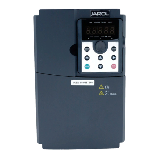
Page 13: Name Of Each Part Of The Inverter
JAC300 Series Inverter User Manual 2.2 Name of each part of the inverter The JAC300 series inverter is a plastic structure type, and the appearance is as shown below: Code name explanation Upper cover Protect internal components keyboard See "Keyboard Operations"... -
Page 14: Basic Technical Specifications
JAC300 Series Inverter User Manual 2.3 Basic technical specifications Item Specification Maximum Vector control:0~500Hz; V/F control:0~500Hz frequency 0.8kHz ~ 12kHz Automatic adjustment of carrier frequency Carrier frequency based on load characteristics Input frequency Digital setting : 0.01Hz Analog setting : Maximum resolution frequency×0.025%... - Page 15 JAC300 Series Inverter User Manual DC braking frequency:0.00Hz~ Maximum frequency DC braking Braking time : 0.0s~36.0s Brake action current value : Built-in brake unit 0.0%~100.0% Jog frequency range:0.00Hz~50.00Hz。 Jog control Jog acceleration/deceleration time0.0s~6500.0s。 The operation panel is given, the control terminal is given, Command source and the serial communication port is given.
-
Page 16: Chapter 3 Installation Instructions
5)Avoid places that are corrosive, flammable, or explosive in the air. 6)Avoid installation in places with oil, dust, and metal dust. 7)JAC300 series plastic casing products are Built-in products, which need to be installed in the final system. The final system should provide corresponding fireproof casing, electrical protective casing and mechanical protective casing, etc., and comply with local laws and... - Page 17 JAC300 Series Inverter User Manual The frequency converter can be mounted on a wall or in a cabinet. The drive must be mounted in the vertical direction. Please check the installation location as described below. 3.1.3 Installation method (1) Mark the position of the mounting hole. For the location of the mounting holes, please refer to the outline drawing of the inverter in the Appendix section;...
- Page 18 JAC300 Series Inverter User Manual (2) Fix the screw or bolt to the marked position; (3) leaning the inverter against the wall; (4) Tighten the fastening screws on the wall. 3.1.4 Single installation Note: The minimum size for B and C is 100mm.
-
Page 19: Electrical Installation
JAC300 Series Inverter User Manual note: 1. When installing inverters with different sizes, please align the upper positions of each inverter before installing. This is convenient for later maintenance. 2. The minimum size requirement for B, D and C is 100mm. - Page 20 JAC300 Series Inverter User Manual Figure 3-2 Single-phase 0.75-2.2kW wiring standard Figure 3.3 Three-phase 0.75-37kW wiring standard Figure 3.4 Three-phase 45-110kW wiring standard (brake resistor matching) Figure 3.5 Three-phase 132-315KW 3.2.2 Main circuit terminal description Inverter main circuit terminal description:...
- Page 21 JAC300 Series Inverter User Manual Figure 3-13 22kW (5041B type) main circuit terminal block Figure 3-14 30kW-37kW (5042B type) main circuit terminal block Figure 3-15 45kW-55kW (5050B type) main circuit terminal block Figure 3-16 75kW-110kW (5061B type) main circuit terminal block...
- Page 22 JAC300 Series Inverter User Manual Figure 3-17 200kW-315kW main circuit terminal block Terminal mark Name Description AC input three-phase power connection point, Three-phase power input R、S、T/L1、L2 single-phase inverter connected to R, S, T any terminal two lines Brake resistor +、PB...
- Page 23 JAC300 Series Inverter User Manual Figure 3-21 Control circuit terminal layout Terminal Function description Category Terminal name symbol Provide power supply of +10V externally, with maximize output External current: 10mA connection of +10V-GND It is generally used as working power +10V power...
- Page 24 JAC300 Series Inverter User Manual Terminal Function description Category Terminal name symbol Digital 2. Input resistance: 2.4kΩ DI2- OP Input 2 3. Voltage range in input level: 9V~30V Digital DI3- OP Input 3 Digital DI4- OP Input 4 Digital DI6- OP...
- Page 25 JAC300 Series Inverter User Manual Terminal Function description Category Terminal name symbol RO1A-RO1C Open terminal 30Vdc ,1A RO2A-RO2C Open terminal Contact drive capacity: Secondary RO2A-RO2B Closed terminal 25V ac,3A,COSØ=0.4 。 interface 30Vdc ,1A Communication Modbus communication interface, 485+,485- Modbus interface non-isolated output 3.2.4 Control loop wiring diagram...
- Page 26 JAC300 Series Inverter User Manual 1) AI analog input terminal: Because weak analog voltage signals are particularly susceptible to external interference, shielded cables are generally required, and the wiring distance should be as short as possible, not more than 20m, as shown in Figure 3-22. In the case where some analog signals are seriously disturbed, a filter capacitor or a ferrite core should be added to the analog signal source side, as shown in Figure 3-23.
- Page 27 JAC300 Series Inverter User Manual Figure 3-24 Schematic diagram of analog input terminal wiring Figure 3-25 Wiring diagram of analog input terminal processing 2) DI digital input terminal: Generally, shielded cables are required, and the wiring distance should be as short as possible, not more than 20m.
- Page 28 JAC300 Series Inverter User Manual Figure 3-27 Multiple inverters DI terminal and drain type wiring ◆Source wiring method (PNP) Figure 3-28 Source wiring method This wiring method must remove the short circuit between the +24V and the OP, connect the +24V to the common terminal of the external controller, and connect the OP to the COM.
- Page 29 JAC300 Series Inverter User Manual Figure 3-29 Wiring diagram of digital output terminal - 29 -...
-
Page 30: Chapter 4 Operation Display
JAC300 Series Inverter User Manual Chapter 4 Operation Display 4.1 Operation and display interface introduction With the operation panel, the inverter can be used to modify the function parameters, the inverter working status monitoring and the inverter running control (starting, stopping). The appearance and... - Page 31 JAC300 Series Inverter User Manual “MF.K” keys. : Unit indicator, used to indicate the unit of the currently displayed data, there are several units: (○ means extinguished; ● means lit) : Hz Frequency unit : A current unit : V Voltage unit : RMP Speed unit : %...
- Page 32 JAC300 Series Inverter User Manual Increment key Increment of data or function code Decrement key Decrease in data or function code In the stop display interface and the operation display interface, the display parameters can be selected Shift key cyclically; when the parameters are modified, the modification bits of the parameters can be selected.
-
Page 33: Chapter 5 Function Parameter List
JAC300 Series Inverter User Manual Chapter 5 Function Parameter List PP-00 is set to a non-zero value, that is, the parameter protection password is set. In the function parameter mode and the user change parameter mode, the parameter menu must be entered after the password is correctly entered. - Page 34 JAC300 Series Inverter User Manual function Factory name Predetermined area change code default terminal command channel ("LOCAL/REMOT" light is on) is controlled by the multi-function input terminals FWD, REV, JOGF, JOGR, etc. Communication command channel ("LOCAL/REMOT" light flashes), the running command is given by the host computer through communication.
- Page 35 JAC300 Series Inverter User Manual function Factory name Predetermined area change code default correspondence curves, among which 3 sets of curves linear relationships points correspondence), and 2 sets of curves are arbitrary curves of 4 points correspondence. Users can pass P4-13~P4-27 function code and A6 group function.
- Page 36 JAC300 Series Inverter User Manual function Factory name Predetermined area change code default When the digital input DI terminal is used as the multi-segment command terminal function, it needs to be set in the P4 group. For details, please refer to the relevant function parameters of the P4 group.
- Page 37 JAC300 Series Inverter User Manual function Factory name Predetermined area change code default frequency source X and the auxiliary frequency source Y), it is necessary to pay attention to: 1. When the auxiliary frequency source is digital timing, the preset frequency (P0-08) does not work.
- Page 38 JAC300 Series Inverter User Manual function Factory name Predetermined area change code default digits: frequency source primary secondary operation relationship 0: main + auxiliary 1: main - auxiliary 2: the maximum of both 3: the minimum of the two The frequency reference channel is selected by this parameter.
- Page 39 JAC300 Series Inverter User Manual function Factory name Predetermined area change code default Upper limit Lower limit frequency P0-14 ~ maximum frequency P0-12 50.00Hz ☆ P0-10 frequency 0.00Hz ~ maximum frequency P0-10 When the upper limit frequency source is set to the...
- Page 40 JAC300 Series Inverter User Manual function Factory name Predetermined area change code default returns to the set value. This feature reduces the chance of the drive overheating alarm. 0.00s ~ 650.00s(P0-19=2) 0.0s ~ 6500.0s(P0-19=1) Model 0s ~ 65000s(P0-19=0) Acceleration Acceleration time refers to the time required for the...
- Page 41 JAC300 Series Inverter User Manual function Factory name Predetermined area change code default Frequency This parameter is used to determine the resolution command P0-22 ★ of all frequency-dependent function codes. resolution 0: no memory 1 : memory This function is only available when the frequency source is digitally set.
- Page 42 JAC300 Series Inverter User Manual function Factory name Predetermined area change code default to the frequency set by P0-25. Figure 6-1 shows the acceleration/deceleration time. When P0-25 acceleration/deceleration time is related to the set frequency. If the set frequency changes frequently, the acceleration of the motor changes, so pay attention to the application.
- Page 43 JAC300 Series Inverter User Manual function Factory name Predetermined area change code default frequency source selection Thousands: automatic running binding frequency source selection The meaning of the above frequency reference channel is the same as the main frequency source X selection P0-03, please refer to P0-03 function code description.
- Page 44 JAC300 Series Inverter User Manual function Factory name Predetermined area change code default resistance Asynchronous Tuning 0.001Ω ~65.535Ω(Inverter power<=55kW ) motor rotor P1-07 ★ 0.0001Ω ~6.5535Ω(Inverter power>55kW) parameter resistance Asynchronous Tuning 0.01mH ~655.35mH (Inverter power<=55kW ) motor leakage P1-08 ★...
- Page 45 JAC300 Series Inverter User Manual function Factory name Predetermined area change code default Use static tuning 2 when the motor has a large inertia load that is not easily disengaged and vector control is required. The motor type nameplate parameters P1-00~P1-05 must be correctly set before the parameters are self-learned.
- Page 46 JAC300 Series Inverter User Manual function Factory name Predetermined area change code default Speed loop P2-01 0.01s ~10.00s 0.50s ☆ integration time 1 Switching P2-02 0.00 ~P2-05 5.00Hz ☆ frequency 1 Speed loop P2-03 proportional gain 1 ~100 ☆ Speed...
- Page 47 JAC300 Series Inverter User Manual function Factory name Predetermined area change code default Increasing the proportional gain and reducing the integration time can speed up the dynamic response of the speed loop. However, if the proportional gain is too large or the integration time is too small, the system can oscillate.
- Page 48 JAC300 Series Inverter User Manual function Factory name Predetermined area change code default 0: Function code P2-10 setting 1: AI1 2: AI2 Torque upper 3: AI3 limit source 4: PULSE setting (DI5) P2-09 ☆ speed control 5: Communication given mode...
- Page 49 JAC300 Series Inverter User Manual function Factory name Predetermined area change code default The vector control current loop PI adjustment parameter, which is automatically obtained after the asynchronous machine is dynamically tuned, generally does not need to be modified. Need to be reminded that the integral regulator of the current loop does not use the integration time as the dimension, but directly sets the integral gain.
- Page 50 JAC300 Series Inverter User Manual function Factory name Predetermined area change code default voltage and rated frequency of group P1. Assume voltage source input For X (X is 0~100% value), the relationship between inverter output voltage V and frequency F is: V/F=2 * X * (motor rated...
- Page 51 JAC300 Series Inverter User Manual function Factory name Predetermined area change code default Multi-point P3-03 0.00Hz~P3-05 0.00Hz ★ frequency point 1 Multi-point P3-04 0.0%~100.0% 0.0% ★ voltage point 1 Multi-point P3-05 P3-03~P3-07 0.00Hz ★ frequency point 2 Multi-point P3-06 0.0%~100.0% 0.0%...
- Page 52 JAC300 Series Inverter User Manual function Factory name Predetermined area change code default 0.0% to 200.0% This parameter is valid only for asynchronous motors. VF slip compensation can compensate the motor speed deviation generated by the asynchronous motor when the load increases, so that the motor speed can be basically stabilized when the load changes.
- Page 53 JAC300 Series Inverter User Manual function Factory name Predetermined area change code default 0 to 200 During the deceleration of the inverter, the overexcitation control can suppress the rise of the bus voltage and avoid overvoltage faults. The larger the overexcitation gain, the stronger the suppression effect.
- Page 54 JAC300 Series Inverter User Manual function Factory name Predetermined area change code default 0: Digital setting (P3-14) 1: AI1 2: AI2 3: AI3 4: PULSE pulse setting (DI5) separated P3-13 5: Multi-segment instructions ☆ voltage source 6: Simple PLC 7: PID 8: Communication given Note: 100.0% corresponds to the rated voltage of...
- Page 55 JAC300 Series Inverter User Manual function Factory name Predetermined area change code default the PA group introduction. 8, communication given The voltage is given by the host computer through communication. The VF separation voltage source selection is similar to the frequency source selection.
- Page 56 JAC300 Series Inverter User Manual function Factory name Predetermined area change code default 1:After the voltage is reduced to 0, the frequency is reduced again. After the V/F split output voltage is first decremented to 0V according to the voltage fall time (P3-15), the frequency is decremented to 0Hz according to the deceleration time (P0-18).
- Page 57 JAC300 Series Inverter User Manual function Factory name Predetermined area change code default returns to the overcurrent speed. After the point is below, the frequency starts to accelerate upward to the target frequency, and the actual acceleration time is automatically lengthened. If the actual acceleration time cannot meet the requirements, the “...
- Page 58 JAC300 Series Inverter User Manual function Factory name Predetermined area change code default n coefficient In the high frequency region, the motor drive current is small, and the speed of the motor drops greatly with respect to the same stall current below the rated frequency. In order to improve the operating characteristics of the motor, the stall operating current above the rated frequency can be reduced, in some centrifuges.
- Page 59 JAC300 Series Inverter User Manual function Factory name Predetermined area change code default Overvoltage stall P3-22 650.0V ~800.0V 760.0V ★ operating voltage Overvoltage P3-23 0:invalid 1:effective ★ stall enable Overvoltage stall suppression P3-24 0 ~100 ☆ frequency gain Overvoltage stall P3-25 0 ~100...
- Page 60 JAC300 Series Inverter User Manual voltage gain Overvoltage stall maximum P3-26 0 ~50Hz ★ rising frequency limit Please note when using a braking resistor or when installing a brake unit or when using an energy feedback unit: Please set P3-11 “overexcitation gain” value to “0” . If it is not “0” , it may cause excessive current during operation.
- Page 61 JAC300 Series Inverter User Manual 4:Forward jog(FJOG ) 5:Reverse jog(RJOG ) (FJOG is jog forward running, RJOG is jog reverse running. Jog running frequency, jog acceleration/deceleration time see description of function codes P8-00, P8-01, P8-02.) 6:Terminal UP 7:Terminal DOWN (The frequency is incremented or decremented when the frequency is given by the external terminal.
- Page 62 JAC300 Series Inverter User Manual 21 : Acceleration/deceleration prohibition (Ensure that the inverter is not affected by external signals (except for the stop command) and maintain the current output frequency.) 22:PID pause (PID temporarily expires, the inverter maintains the current output frequency, and the PID adjustment of the frequency source is no longer performed.)
- Page 63 JAC300 Series Inverter User Manual (Through the four states of these two terminals, 4 sets of motor parameters can be switched. For details, see Attachment 3.) 43:PID Parameter switching (When the PID parameter switching condition is DI terminal (PA-18=1), when the terminal is invalid, the PID parameter uses PA-05 to PA-07;...
- Page 64 JAC300 Series Inverter User Manual Multi-segment PC-01 instruction1 Multi-segment PC-02 instruction 2 Multi-segment PC-03 instruction 3 Multi-segment PC-04 instruction 4 Multi-segment PC-05 instruction 5 Multi-segment PC-06 instruction 6 Multi-segment PC-07 instruction 7 Multi-segment PC-08 instruction 8 Multi-segment PC-09 instruction 9...
- Page 65 JAC300 Series Inverter User Manual acceleration time 4 P8-07 、P8-08 The following table shows the function description of the motor selection terminal. Terminal 1 Acceleration or deceleration Corresponding time selection parameter Motor 1 P1, P2 group Motor 2 A2 group 0.000s~1.000s...
- Page 66 JAC300 Series Inverter User Manual This parameter defines four different ways to control the operation of the drive via external terminals. Note: For convenience of explanation, the following three terminals DI1, DI2, and DI3 in the multi-function input terminals of DI1 to DI10 are selected as external terminals.That is, the functions of the three terminals DI1, DI2, and DI3 are selected by setting the values of P4-00 to P4-02.
- Page 67 JAC300 Series Inverter User Manual reverse direction As shown in the figure above, in the closed state of K1, K2 disconnects the inverter from forward rotation, K2 closes the inverter reverse rotation; K1 disconnects and the inverter stops running. 2:Three-wire control mode 1:This mode DI3 is the enable terminal, and the direction is controlled by DI1 and DI2 respectively.
- Page 68 JAC300 Series Inverter User Manual As shown in the figure above, in the control mode, when the SB1 button is closed, press the SB2 button to turn the inverter forward. Press the SB3 button to reverse the inverter. When the SB1 button is turned off, the inverter stops.During normal start-up and operation, it is necessary to keep the SB1...
- Page 69 JAC300 Series Inverter User Manual 0.001Hz/s ~65.535Hz/s Used to set the terminal UP/DOWN to adjust the set Terminal frequency, the speed of the frequency change, that is, UP/DOWN the amount of change per second. P4-12 1.00Hz/s ☆ When P0-22 (frequency point) is 2, the value ranges Rate of from 0.001 Hz/s to 65.535 Hz/s.
- Page 70 JAC300 Series Inverter User Manual In different applications, the meaning of the nominal value corresponding to 100.0% of the analog setting is different. For details, please refer to the description of each application part. The following illustrations are for two typical settings:...
- Page 71 JAC300 Series Inverter User Manual AI curve 3 maximum input P4-26 -100.0% ~+100.0% 100.0% ☆ correspondin g setting filtering P4-27 0.00s ~10.00s 0.10s ☆ time PULSE curve P4-28 -10.00V ~P4-25 0.00V ☆ minimum input PULSE curve minimum P4-29 -100.0% ~+100.0% 0.0%...
- Page 72 JAC300 Series Inverter User Manual curve4(4 points, see A6-00 ~ A6-07) curve5(4 Point, see A6-08 ~ A6-15 ) AI2 Curve selection(1 ~5,Same Ten digit above) Hundred AI3 Curve selection(1 ~5,Same s digit above) The ones digit of the function code, ten digits and hundred digits are used to select, the analog input AI1, AI2, AI3 corresponding setting curve.
- Page 73 JAC300 Series Inverter User Manual If 0 is selected, when the AI input is lower than the “ minimum input ” , the corresponding setting of the analog quantity is the curve “ minimum input corresponding setting ” determined by the function code (P4-14, P4-19, P4- 24 ).
- Page 74 JAC300 Series Inverter User Manual B-RO1C) Extended relay P5-03 function selection ☆ (RO2A-RO2B-RO2C) 0:no output 1: When the inverter is running (The inverter is running, there is output frequency (can be zero), and the ON signal is output at this time.) 2:Fault output (failure for free stop) When the inverter fails and the fault stops, the ON signal is output.
- Page 75 JAC300 Series Inverter User Manual 15:Ready to run When the main circuit of the inverter and the control loop power supply have been stabilized, and the inverter does not detect any fault information, the inverter outputs the ON signal when it is in the operable state.
- Page 76 JAC300 Series Inverter User Manual When the running frequency reaches the lower limit frequency, the ON signal is output. This signal is also ON during the stop state. 38:Alarm output (all faults) When the inverter fails and the processing mode of the fault is continuous operation, the inverter alarm output.
- Page 77 JAC300 Series Inverter User Manual P5-13 AO2 Gain -10.00 ~+10.00 1.00 ☆ The above function codes are generally used to correct the zero drift of the analog output and the deviation of the output amplitude. It can also be used to customize the required AO output curve.
- Page 78 JAC300 Series Inverter User Manual speed. However, setting too large may cause the tracking effect to be unreliable. Starting P6-03 0.00Hz~10.00Hz 0.00Hz ☆ frequency Start P6-04 frequency 0.0s ~100.0s 0.0s ★ hold time To ensure motor torque at start-up, set the appropriate starting frequency. In order to fully establish the magnetic flux when the motor starts, the starting frequency needs to be maintained for a certain period of time.
- Page 79 JAC300 Series Inverter User Manual response speed. Starting DC braking is only effective when the startup mode is direct startup. At this time, the inverter first performs DC braking according to the set starting DC braking current, and then starts running after the DC braking time is started.
- Page 80 JAC300 Series Inverter User Manual When the set frequency is above the rated frequency, the acceleration/deceleration time is: ƒ is the set frequency,ƒb is the rated frequency of the motor, and T is the time from the 0 frequency acceleration to the rated frequency ƒb.
- Page 81 JAC300 Series Inverter User Manual Stop P6-11 braking start 0.00Hz~Maximum frequency 0.00Hz ☆ frequency brake P6-12 0.0s ~100.0s 0.0s ☆ waiting time braking P6-13 current 0% ~100% ☆ stop braking P6-14 0.0s ~100.0s 0.0s ☆ time at stop DC braking start frequency at stop: During the deceleration stop, when the running frequency decreases to this frequency, the DC braking process starts.
- Page 82 JAC300 Series Inverter User Manual braking process. 30% ~200% Speed The maximum current limit of the speed tracking Model P6-18 tracking process is within the range of the “ speed tracking determinat ★ current current” setting. If the set value is too small, the effect of the speed tracking will be worse.
- Page 83 JAC300 Series Inverter User Manual Bit11: AI3 Voltage(V) Bit12: Count value Bit13: Length value Bit14: Load speed display Bit15: PID set up 0000~FFFF Bit00:PID Feedback Bit01:PLC stage Bit02:PULSE Input pulse frequency (kHz) Bit03:Operating frequency 2(Hz) Bit04:Remaining running time Bit05:AI1 pre-correction voltage(V) Bit06:AI2 pre-correction voltage(V)
- Page 84 JAC300 Series Inverter User Manual Bit10:Load speed Bit11:PID set up Bit12:PULSE Input pulse frequency(kHz) 0.0001~6.5000 When the load speed needs to be displayed, the Load speed corresponding relationship between the inverter output display P7-06 1.0000 ☆ frequency and the load speed is adjusted by this factor parameter.
- Page 85 JAC300 Series Inverter User Manual determinat Model deceleration P8-08 0.0s ~6500.0s determinat ☆ time 4 The JAC300 provides 4 sets of acceleration/deceleration time, which are P0-17\P0-18 and the above three groups of acceleration and deceleration time. The definitions of the 4 groups of acceleration and deceleration time are exactly the same. Please refer to the related instructions of P0-17 and P0-18.
- Page 86 JAC300 Series Inverter User Manual reversal Set the transition time at the output 0Hz during the dead time forward/reverse transition of the inverter, as shown below: Reverse P8-13 frequency 0:allow 1 :Prohibited ☆ prohibition frequency 0:Running at the following frequency limit...
- Page 87 JAC300 Series Inverter User Manual arrival time multi-function digital DO outputs an ON signal. 0h~65000h Used to set the running time of the inverter. cumulative P8-17 When the accumulated running time (P7-09) reaches ☆ arrival this set running time, the inverter multi-function digital time DO outputs ON signal.
- Page 88 JAC300 Series Inverter User Manual When the running frequency is higher than the frequency detection value, the multi-function output DO of the inverter outputs ON signal, and after the frequency is lower than the certain frequency value of the detected value, the DO output ON signal is canceled.
- Page 89 JAC300 Series Inverter User Manual 0:invalid 1:effective This function code is used to set whether the skip frequency valid during acceleration deceleration. When set to valid, when the running frequency is in the skip frequency range, the actual running frequency will skip the set skip frequency boundary.
- Page 90 JAC300 Series Inverter User Manual frequency points Deceleration time 1 and deceleration P8-26 0.00Hz~Maximum frequency 0.00Hz ☆ time 2 switch frequency point This function is valid when the motor is selected as motor 1 and the acceleration/deceleration time is not selected by DI terminal switching. It is used to select different acceleration/deceleration time according to the operating frequency range without running through the DI terminal during the running of the inverter.
- Page 91 JAC300 Series Inverter User Manual frequency detection value 1 Arbitrary arrival frequency P8-31 0.0%~100.0%(Maximum frequency) 0.0% ☆ detection width 1 Arbitrary arrival P8-32 frequency 0.00Hz~Maximum frequency 50.00Hz ☆ detection value 2 0.0%~100.0%(Maximum frequency) When the output frequency of the inverter is within the...
- Page 92 JAC300 Series Inverter User Manual When the output current of the frequency inverter is less than or equal to the zero current detection level and the duration exceeds the zero current detection delay time, the inverter multi-function DO outputs ON signal. The figure below shows a schematic diagram of zero current detection.
- Page 93 JAC300 Series Inverter User Manual Arbitrary arrival P8-41 0.0%~300.0%( Motor rated current) 0.0% ☆ current 2 width When the output current of the frequency inverter is within the positive and negative detection width of any set current, the frequency inverter multi-function DO outputs ON signal.
- Page 94 JAC300 Series Inverter User Manual limit of input voltage protection value When the value of analog input AI1 is greater than P8-46, or the AI1 input is less than P8-45, the inverter multi-function DO outputs “AI1 input overrun” ON signal to indicate whether the input voltage of AI1 is within the set range.
- Page 95 JAC300 Series Inverter User Manual is calculated or not is affected by the function code PA-28. At this time, the PID stop operation (PA-28=1) must be selected. 0.0 ~6500.0 minute arrival When the running time of this startup reaches this P8-53 0.0Min...
- Page 96 JAC300 Series Inverter User Manual 1)When the motor running current reaches 175% of the rated motor current, the motor is overloaded after 2 minutes of continuous operation.(Err11); Under the condition that the motor running current reaches 115% of the rated motor current, the motor overload (Err11) is reported after continuous operation for 80 minutes.
- Page 97 JAC300 Series Inverter User Manual overload is calculated as follows: T = T1 + (T2 - T1)*(I – I1)/( I2 –I1) = 4 + (6 - 4)*(150% – 145%)/( 155% –145%) = 5(分钟)It can be concluded that the motor needs to be overloaded for 2 minutes at 150% motor current, and the motor overload protection gain is: P9-01 = 2 ÷...
- Page 98 JAC300 Series Inverter User Manual Fault action selection 0:No action P9-10 ☆ during 1:action automatic fault reset Fault auto P9-11 0.1s ~100.0s 1.0s ☆ reset interval Single digit:Input phase loss protection option Ten digit:Contactor suction protection option 0:Prohibited 1:allow Choose whether to protect the input phase loss or contactor pull-in.
- Page 99 JAC300 Series Inverter User Manual 0:fault free 1:Reserved 2:Acceleration over current 3:Deceleration over current 4:Constant speed over current First fault P9-14 - ● 5:Acceleration over voltage type 6:Deceleration over voltage 7:Constant speed over voltage 8:Buffer resistor overload 9:Undervoltage 10:Frequency inverter overload 11:Motor overload...
- Page 100 JAC300 Series Inverter User Manual recent) fault Input terminal status for the third P9-20 - - ● (most recent) fault Output terminal status for the P9-21 - - ● third (most recent) fault Inverter status at the third (most P9-22 -...
- Page 101 JAC300 Series Inverter User Manual fault Run time at P9-34 second - - ● fault Frequency P9-37 at the first - - ● fault Current P9-38 - - ● the first fault Bus voltage P9-39 at the first - -...
- Page 102 JAC300 Series Inverter User Manual single digit) Ten thousand digits:Abnormal communication(Err16) (same as single digit) Single digit:Reserved Ten digits : Abnormal function code read and write Fault (Err21) protection 0 Free Downtime P9-48 00000 ☆ action 1 Stop by downtime mode selection 2 Hundreds digit:Reserved...
- Page 103 JAC300 Series Inverter User Manual occurs 0.0%~100.0% (100.0% Corresponding to the maximum frequency P0-10) When a fault occurs during the running of the Backup frequency inverter and the fault is handled in the P9-55 frequency is 100.0% ☆ continuous mode, the inverter displays A** and runs at abnormal the frequency determined by P9-54.
- Page 104 JAC300 Series Inverter User Manual voltage Instantaneous stop non-stop P9-61 0.00s ~100.00s 0.50s ☆ voltage rise judgment time Instantaneous stop and stop action P9-62 60.0% ~100.0%( Standard bus voltage) 80.0% ☆ judgment voltage Instantaneous stop non-stop P9-71 0 ~100 ☆...
- Page 105 JAC300 Series Inverter User Manual If the load-shedding protection function is valid, when the inverter output current is less than the load-drop detection level P9-64 and the duration is longer than the load-off detection time P9-65, the inverter output frequency is automatically reduced to 7% of the rated frequency. During load-shedding protection, if the load recovers, the drive automatically resumes to operate at the set frequency.
- Page 106 JAC300 Series Inverter User Manual PA-01 Numerical 0.0%~100.0% 50.0% ☆ given 0:AI1 1:AI2 2:AI3 3:AI1-AI2 PA-02 Feedback 4:PLUSE Pulse given ☆ source 5:Communication given 6:AI1+AI2 7:MAX(|AI1|, |AI2|) 8:MIN(|AI1|, |AI2|) 0:Positive action When the feedback signal of the PID is less than the given amount, the inverter output frequency rises.
- Page 107 JAC300 Series Inverter User Manual Proportional gain Kp1 : Determine the adjustment strength of the entire PID regulator. The larger the Kp1, the greater the adjustment intensity. The parameter 100.0 indicates that when the deviation between the PID feedback amount and the given amount is 100.0%, the PID regulator adjusts the output frequency command to the maximum frequency.
- Page 108 JAC300 Series Inverter User Manual required for the PID reference value to change from 0.0% to 100.0%. When the PID reference changes, the PID reference value changes linearly according to the given change time, which reduces the adverse effects of the given sudden change on the system.
- Page 109 JAC300 Series Inverter User Manual The two sets of PID parameters can be switched by the multi-function digital DI terminal or automatically according to the deviation of the PID. When the multi-function DI terminal is selected for switching, the multi-function terminal function selection should be set to 43 (PID parameter switching terminal).
- Page 110 JAC300 Series Inverter User Manual output deviation PA-23 0.00% ~100.00% 1.00% ☆ positive maximum output deviation PA-24 0.00% ~100.00% 1.00% ☆ reverse maximum This function is used to limit the difference between PID output two beats (2ms/beat) in order to suppress the PID output from changing too fast and stabilize the inverter operation.
- Page 111 JAC300 Series Inverter User Manual minimum value, you can choose whether to stop the integration. If you choose to stop the integration, then the PID integration stops counting, which may help reduce the overshoot of the PID. Feedback 0.0%:Do not judge feedback loss PA-26 0.0%...
- Page 112 JAC300 Series Inverter User Manual 0: Relative to the center frequency (P0-07 frequency Swing source) frequency For the variable swing system. The swing varies with PB-00 ☆ the center frequency (set frequency). setting 1: relative to the maximum frequency (P0-10) method For a fixed swing system, the swing is fixed.
- Page 113 JAC300 Series Inverter User Manual Pulse number PB-07 0.1 ~6553.5 100.0 ☆ per meter The above function code is used for fixed length control. The length information needs to be collected through the multi-function digital input terminal. The number of pulses sampled by the terminal is divided by the number of pulses per meter PB-07, and the actual length PB-06 can be calculated.
- Page 114 JAC300 Series Inverter User Manual PC-04 Multi-segment instruction 4 -100.0% ~100.0% 0.0% ☆ PC-05 Multi-segment instruction 5 -100.0% ~100.0% 0.0% ☆ PC-06 Multi-segment instruction 6 -100.0% ~100.0% 0.0% ☆ PC-07 Multi-segment instruction 7 -100.0% ~100.0% 0.0% ☆ PC-08 Multi-segment instruction 8 -100.0% ~100.0%...
- Page 115 JAC300 Series Inverter User Manual When used as a frequency source, the PLC has three modes of operation. These three modes are not available as a VF separation voltage source. among them: 0: Single run end shutdown After the inverter completes a single cycle, it will automatically stop and need to give the running command again to start.
- Page 116 JAC300 Series Inverter User Manual The PLC stop memory records the running phase and running frequency of the previous PLC when it stops, and continues to run from the memory phase in the next run. If you choose not to remember, the PLC process will be restarted each time you start.
- Page 117 JAC300 Series Inverter User Manual Simple acceleration/deceler PC-29 0 ~3 ☆ ation time selection Simple PLC 6th run PC-30 0.0s(h)~6553.5s(h) 0.0s(h) ☆ time Simple acceleration/deceler PC-31 0 ~3 ☆ ation time selection Simple PLC 7th run PC-32 0.0s(h)~6553.5s(h) 0.0s(h) ☆...
- Page 118 JAC300 Series Inverter User Manual Simple 12th PC-42 0.0s(h)~6553.5s(h) 0.0s(h) ☆ run time Simple 12th PC-43 acceleration/deceler 0 ~3 ☆ ation time selection Simple 13th PC-44 0.0s(h)~6553.5s(h) 0.0s(h) ☆ run time Simple PLC section 13 acceleration and PC-45 0 ~3 ☆...
- Page 119 JAC300 Series Inverter User Manual Single digit:MODBUS 0:300BPS 1:600BPS 2:1200BPS Communicati PD-00 3:2400BPS 4:4800BPS 5:9600BPS ☆ on baud rate 6:19200BPS 7:38400BPS 8:57600BPS 9:115200BPS MODBUS 0: no parity (8-N-2) 1: even parity (8-E-1) PD-01 ☆ Data Format 2: odd parity (8-O-1) 3: no parity (8-N-1) Local 0:Broadcast address...
- Page 120 JAC300 Series Inverter User Manual 0: no operation 01: Restore factory parameters, excluding motor parameters After setting PP-01 to 1, most of the inverter's function parameters are restored to the factory default parameters, but the motor parameters, frequency command decimal...
- Page 121 JAC300 Series Inverter User Manual 3: AI3 4: PLUSE pulse given source 5: Communication given 6: MIN (AI1, AI2) selection 7: MAX (AI1, AI2) torque control (1-7 full scale of the option, corresponding to the A0-03 mode number setting) Torque digital...
- Page 122 JAC300 Series Inverter User Manual reverse maximum frequency It is used to set the forward or reverse maximum running frequency of the inverter under the torque control mode. When the inverter torque is controlled, if the load torque is less than the motor output torque, the motor speed will continue to rise.
- Page 123 JAC300 Series Inverter User Manual Fast current 0: not enabled A5-04 limiting ☆ 1: enable enable 60.0% ~140.0% It is used to set the voltage value of the inverter undervoltage fault Err09. The inverter with different voltage levels is 100.0%, corresponding to different voltage points, respectively:...
- Page 124 JAC300 Series Inverter User Manual function name Display range mailing address code U0-03 Output voltage (V) 0V~1140V 7003H U0-04 Output current (A) 0.00A~655.35A 7004H U0-05 Output power (kW) 0~32767 7005H Output torque (%) Motor output U0-06 -200.0%~200.0% 7006H torque percentage output value...
- Page 125 JAC300 Series Inverter User Manual function name Display range mailing address code U0-14 Load speed display 0~65535 700EH U0-15 PID set up 0~65535 700FH U0-16 PID Feedback 0~65535 7010H The PID set value and feedback value are displayed. The value format is as follows:...
- Page 126 JAC300 Series Inverter User Manual function name Display range mailing address code U0-30 Main frequency X display 0.00Hz~500.00Hz 701EH U0-31 Auxiliary frequency Y display 0.00Hz~500.00Hz 701FH When P7-12 (load speed display decimal point) is 1, the display range is -500.00Hz to 500.00Hz When P7-12 (load speed display decimal point) is 2, the display range is -3200.0Hz ~ 3200.0Hz...
- Page 127 JAC300 Series Inverter User Manual function name Display range mailing address code Visually display whether terminal functions 41 to 59 are valid Display mode is similar to U0-43 The digital tube represents functions 41 to 48, 49 to 56, 57 to 59 from right to left.
-
Page 128: Chapter 6 Selection And Size
JAC300 Series Inverter User Manual Chapter 6 Selection and Size 6.1 Inverter electrical specifications 表 6-1 JAC300 Inverter model and technical data Adapter motor heat power Input Output Power supply Inverter model Current Current consu capacity mption Single phase power supply:220V,50/60Hz JAC300-0R4GB-S2-5013 0.016... -
Page 129: Inverter Appearance And Size
JAC300-55G-4-5050B 1.80 JAC300-75G-4-5061B 1.84 JAC300-90G-4-5061B 2.08 JAC300-110G-4-5061B 2.55 JAC300-132G-4-5063 3.06 JAC300-160G-4-5063 3.61 JAC300-200G-4-5071B 4.42 JAC300-220G-4-5071B 4.87 JAC300-250G-4-5083 5.51 JAC300-280G-4-5083 6.21 JAC300-315G-4-5083 7.03 6.2 Inverter appearance and size Figure 6-1 JAC300 series Plastic structure dimensions and installation dimensions - 129 -... -
Page 130: Keyboard Size
JAC300 Series Inverter User Manual Figure 6-2 JAC300 series sheet metal structure dimensions and installation dimensions Table 6-2 JAC300 appearance and mounting hole size A(mm) B(mm) H(mm) W(mm) D(mm) Power Mounting model (KW) aperture Installation size Dimensions (mm) 5013 0.75-5.5 φ5... -
Page 131: Selection Of Brake Unit And Braking Resistor
JAC300 Series Inverter User Manual Figure 6-4 Keyboard bracket opening size 6.5 Selection of brake unit and braking resistor Table 6-3 JAC300 Inverter Brake Kit Selection Table Inverter model Brake resistor Braking Brake Remarks recommended resistor unit power recommended resistance... -
Page 132: Chapter 7 Maintenance And Troubleshooting
JAC300 Series Inverter User Manual JAC300-22GB-4-5041B 1500W ≥22Ω JAC300-30G-4-5042B 2500W ≥16Ω JAC300-37G-4-5042B 3.7 kW ≥12.6 Ω JAC300-45G-4-5050B 4.5 kW ≥9.4Ω JAC300-55G-4-5050B 5.5 kW ≥9.4Ω Optional JAC300-75G-4-5061B 7.5 kW ≥6.3Ω JAC300-90G-4-5061B 4.5 kW×2 ≥9.4Ω×2 JAC300-110G-4-5061B 5.5 kW×2 ≥9.4Ω×2 JAC300-132G-4-5063 6.5 kW×2 ≥6.3Ω×2... - Page 133 JAC300 Series Inverter User Manual Daily inspection items: 1) Whether the sound changes abnormally when the motor is running 2) Is vibration generated during motor operation? 3) Does the inverter installation environment change? 4) Is the inverter cooling fan working properly?
- Page 134 JAC300 Series Inverter User Manual Judging criteria: Whether there are cracks in the fan blades, etc., whether the sound has abnormal vibration when starting up. 2) Filter electrolytic capacitor Possible causes of damage: poor input power quality, high ambient temperature, frequent load jumps, and electrolyte aging.
-
Page 135: Fault Alarm And Countermeasure
JAC300 Series Inverter User Manual 7) The relevant service fees are calculated according to the uniform standards of the manufacturer. If there is a contract, the contract is prioritized. 7.2 Fault alarm and countermeasure When a fault occurs in the operation of the JAC300 inverter system, the inverter will immediately protect the motor from output and the inverter fault relay contact will act. - Page 136 JAC300 Series Inverter User Manual Operation Fault name panel Troubleshoot the cause Troubleshooting display 1. There is grounding or short circuit 1. Eliminate peripheral faults in the output circuit of the inverter. Perform motor parameter 2. The control mode is vector and...
- Page 137 JAC300 Series Inverter User Manual Operation Fault name panel Troubleshoot the cause Troubleshooting display process. install braking resistor Control 1. The input voltage is not within the 1. Adjust voltage Err08 power failure scope specified by the specification. specification 1, instantaneous power outage 2.
- Page 138 JAC300 Series Inverter User Manual Operation Fault name panel Troubleshoot the cause Troubleshooting display of the inverter when the motor is In addition to failure running 3. Seek technical support 3, the drive board is abnormal 4, seeking technical support...
- Page 139 JAC300 Series Inverter User Manual Operation Fault name panel Troubleshoot the cause Troubleshooting display EEPROM Read and Err21 1、EEPROM Chip damage 1、Replace the main control board write failure Inverter 1, according to overvoltage fault 1、Overpressure hardware Err22 handling 2、Overcurrent failure 2、Overcurrent fault handling...
-
Page 140: Fault Alarm And Countermeasure
JAC300 Series Inverter User Manual Operation Fault name panel Troubleshoot the cause Troubleshooting display 1. Reduce the load and check the 1. Is the load too large or the motor Wave-by-wav motor mechanical stalls? e current Err40 conditions. 2, the frequency converter selection... - Page 141 JAC300 Series Inverter User Manual Serial Fault phenomenon possible reason Solution number The grid voltage is not or too low; The switching power supply on the inverter drive board is faulty; rectifier bridge Check the input power; damaged; Check the bus voltage;...
-
Page 142: Appendix C: Modbus Communication Protocol
Appendix C: Modbus Communication Protocol JAC300 series inverters provide RS485 communication interface and support Modbus-RTU slave communication protocol. The user can realize centralized control through computer or PLC, set the inverter running command through the communication protocol, modify or read the function code parameters, and read the working status and fault information of the inverter. - Page 143 JAC300 Series Inverter User Manual including: function code requiring action, transmission data and error checking. The response of the slave also adopts the same structure, including: action confirmation, return data and error check. If the slave receives an error while receiving information, or fails to complete the action requested by the host, it will organize a fault message as a response to the host.
- Page 144 C.2 Communication data structure The Modbus protocol communication data format of JAC300 series inverter is as follows. The inverter only supports reading or writing of Word type parameters. The corresponding communication read operation command is 0x03;...
- Page 145 JAC300 Series Inverter User Manual If the slave detects a communication frame error, or the read/write is unsuccessful due to other reasons, it will reply the error frame. Data frame field description: Frame header START Idle more than 3.5 characters of transmission time Slave address ADR Address range:1 ~247 ;0 =Broadcast address...
- Page 146 JAC300 Series Inverter User Manual Data H The data to be acknowledged, or the data to be written, is transmitted Data L with the high byte first and the low byte after. CRC CHK High position Detection value: CRC16 check value. When transmitting, the high byte is first and the low byte is after.
- Page 147 JAC300 Series Inverter User Manual crc_value^=*data_value++; for(i=0;i<8;i++ ) if(crc_value&0x0001) crc_value=(crc_value>>1)^0xa001; else crc_value=crc_value>>1; return(crc_value); The address of the communication parameter defines the function of reading and writing function code (some function codes cannot be changed and are only used by the manufacturer or monitored): C .
- Page 148 JAC300 Series Inverter User Manual Function code group Communication access Communication modify the function number address code address in RAM P0~PE group 0xP000 ~0xPEPF 0x0000~0x0EPF A0~AC group 0xA000 ~0xACPF 0x4000~0x4CPF U0 group 0x7000~0x70PF Note that since the EEPROM is frequently stored, it will reduce the lifetime of the EEPROM, so some function codes are in communication.
- Page 149 JAC300 Series Inverter User Manual Feedback speed 1004H Output current 1014H 0.1Hz 1005H Output Power 1015H Remaining running time Parameter Parameter Parameter Description Parameter Description address address AI1 Pre-correction 1006H Output torque 1016H voltage AI2 Pre-correction 1007H Running speed 1017H...
- Page 150 JAC300 Series Inverter User Manual 0003:Forward turn 0007:Fault reset 0004:Reverse jog Read the inverter status: (read only) Status word address Status word address 0001:Forward running 0002:Reverse run 3000H 0003:Downtime Parameter lock password check: (If the return is 8888H, it means the password check is passed)
- Page 151 JAC300 Series Inverter User Manual 0004: Constant speed over 0017: Motor short circuit to ground current 001A: Run time arrives 0005: Accelerated overvoltage 001B: User-defined fault 1 0006: Deceleration 001C: User-defined fault 2 overvoltage 001D: Power on time arrives 0007: Constant speed...
- Page 152 JAC300 Series Inverter User Manual 0: No parity: data format <8, N, 2> Predetermined 1: Even check: data format <8, E, 1> area 2: Odd parity: data format <8, O, 1> 3: No parity: data format <8-N-1> The data format set by the host computer and the inverter must be the same. Otherwise, the communication cannot be performed.
-
Page 153: Warranty Agreement
JAC300 Series Inverter User Manual protocol selection Predetermined 0: Non-standard Modbus protocol; 1: Standard area Modbus protocol PD-05=1: Select the standard Modbus protocol. PD-05=0: When the command is read, the number of bytes returned by the slave is one byte more than the standard Modbus protocol. - Page 154 JAC300 Series Inverter User Manual 4) The collection of maintenance costs shall be subject to the latest revised “Maintenance Price List” of our company. 5) This warranty card will not be reissued under normal circumstances. Please be sure to keep this card and present it to the maintenance personnel at the time of warranty.
- Page 155 JAC300 Series Inverter User Manual Unit address: client company name: Contact: information Postal code: contact number: Product number: product Body barcode (paste here): information Agent name: (Maintenance time and content): malfunction information Repair man: - 155 -...
Need help?
Do you have a question about the JAC300 Series and is the answer not in the manual?
Questions and answers