Table of Contents
Advertisement
Quick Links
DECLARATIONS
U.S. Radio Frequency FCC Compliance
This device complies with Part 15 of the FCC Rules. Operation is subject to the following two
conditions:
(1) This device may not cause harmful interference, and
(2) This device must accept any interference received, including interference that may cause
undesired operation.
This equipment has been tested and found to comply with the limits for a Class B digital
device, pursuant to Part 15 of the FCC Rules. These limits are designed to provide reasonable
protection against harmful interference in a residential installation. This equipment generates,
uses, and can radiate radio frequency energy and, if not installed and used in accordance with
the instructions, may cause harmful interference to radio communications. However, there is
no guarantee that interference will not occur in a particular installation. If this equipment does
cause harmful interference to radio or television reception, which can be determined by turning
the equipment off and on, the user is encouraged to try to correct the interference by one or
more of the following measures:
• Reorient or relocate the receiving antenna.
• Increase the separation between the equipment and receiver.
• Connect the equipment into an outlet on a circuit different from that to which the receiver is
connected.
• Consult the dealer or an experienced radio/TV technician for help.
Any Changes or modifications not expressly approved by the party responsible for compliance
could void the user's authority to operate the equipment.
ISED RSS Warning:
This device complies with Innovation, Science and Economic Development Canada license-
exempt RSS standard(s). Operation is subject to the following two conditions: (1) this device may
not cause interference, and (2) this device must accept any interference, including interference
that may cause undesired operation of the device.
QUICK INDEX
Settings
Steps
1 Pairing
P1 (hold for 2s) > Stop (hold for 2s
2
Switch Rotating Direction Up + Down (hold for 2s)
Upper Limit: Up (hold for 2s) > Up + Stop (hold for 2s)
3 Set Upper/Lower Limits
Lower Limit: Down (hold for 2s) > Down + Stop (hold for 2s)
4 Add/Remove Fav. Position P2 > Stop > Stop
5 Roller/Sheer Mode Switch Up + Down (hold for 5s) > Stop
Upper: Up + Stop (hold for 5s) > Up or Dn > Up + Stop (hold for 2s)
6 Adjusting the Limits
Lower: Dn + Stop (hold for 5s) > Up or Dn > Dn + Stop (hold for 2s)
7 Add/Remove a Remote
P2 (existing) > P2 (existing) > P2 (new)
Increase Motor Speed: P2 > Up > Up
8 Speed Regulation
Decrease Motor Speed: P2 > Down > Down
TROUBLESHOOTING
Problem - The motor has no response
Cause
Solution
Battery in motor is depleted
Recharge with compatible AC adaptor and check
connection and positioning of solar panel
Insufficient charging from Solar Panel
Check connection and orientation of solar panel.
Wall switch battery is discharged
Replace battery or check placement.
or not installed properly
Radio interference / shielding
Ensure wall switch and the antenna on the motor
are positioned away from metal objects.
Receiver distance is too far
Move wall switch to a closer position.
Power failure
Check power supply to motor is connected/active.
Incorrect wiring
Check that wiring is connected correctly.
Problem - The Motor beeps 10 times when in use
Cause
Solution
Battery voltage is low/ SolarPanel Issue
Recharge with AC adapter or check connection and
positioning of solar PV panel
Problem - Cannot program a single motor (multiple motors respond)
Cause
Solution
Multiple Motors are paired to the same
Always reserve a channel for programming.
BEST PRACTICE - Provide an extra 15 channel
remote in your multi-motor projects for individual
control and programming purposes
To work on a single motor at a time, place all other
motors into sleep mode. Press the "P1" button
(about 6 ec) on the motor head until motor jog x2
and beep x2.
)
PROGRAMMING AND USERS GUIDE
SPECIFICATIONS
Voltage
Radio Frequency
Transmitting Power
Operating Temperature
RF Modulation
Lock Function
IP Rating
Transmission Distance
SAFETY INSTRUCTIONS
SAFETY INSTRUCTIONS
Declarations
1. Do not expose motor to humid, damp, or extreme temperature conditions.
2. Do not drill into motor.
3. Do not cut the antenna. Keep it clear from metal objects.
FCC Text - text 01
4. Do not allow children to play with this device.
5. If the power cable or connector is damaged, do not use.
6. Ensure the power cable and antenna are clear and protected from moving parts.
7. Cable routed through walls should be properly isolated.
8. Motor should be mounted in horizontal position only.
9. Before installation, remove unnecessary cords and disable equipment not needed for powered
operation.
Do not dispose of in general waste.
Do not dispose of in general waste.
Please recycle batteries and damaged electrical products appropriately.
Please recycle batteries and damaged electrical products appropriately.
TM
SURFACE MOUNTED
WALL SWITCH
3V (CR2430)
433.92 MHz Bi-directional
10 milliwatt
14°F to 122°F (-10°C to 50°C)
FSK
Yes
IP20
up to 200m (outdoor)
AMP25B
Charging Instructions
Add A zoom in on the
Micro-USB Port
Instruction
charging port
LED light
Features
P1 button
Lithium Battery Switch
This motor has a built in Li-ion battery pack with integrated charge management.
Max power input for recharging: 5V 2A.
Before first use please charge motor for 6 hours. Using 5V charger (most phones charger is 5V ) .
Fields of Application
During operation, when the motor starts, the buzzer will beep 10 times, indicating a low-voltage alarm and
needs to be charged.
During operation, the voltage was detected to be too low, the battery was about to run out, the battery stopped
running and needed to be recharged.
Rechargeable Battery
Roller
Sheer
Revolve
Roman shades
Specifications
Blinking red:
Blinking green:
Solid green:
Low battery alert
Charging is processing
Battery has
finished charging.
Working temperature: -10℃ ~ +50℃
Radio Frequency: 433.925MHz
Input Voltage: USB 5V 1A / USB 5V 2A
Maximum Running Time: 6 minutes
The motor is suitable for motorization of roller blinds, sheer shadings, roman shades, and zebra shades.
P1 Button Instructions
Following data for reference
Rated Torque
Rated Speed
Rated Power
Model
(N.m)
(rpm)
(W)
AMP25B - 0.7/34
0.7
34
8
AMP25B -1.1/28
1.1
28
8
Add visual explanation of P1 - file 02
Attention
Never drop, knock, drill or submerge the motor. Keep the power cable in right position as following.
Important safety instructions to be read before installation.
Incorrect installation can lead to serious injury and will void manufacturer's liability and warranty.
-1-
Safety
1. Do not expose motor to humid, damp or extreme temperature conditions.
2. Do not drill into motor.
3. Do not cut the antenna and keep it clear from metal objects.
4. Do not allow children to play with this device.
5. If power cable or connector is damaged, do not use.
6. Ensure correct crown and drive adaptor are used.
7. Ensure power cable and aerial is clear and protected from moving parts.
8. Cable routed through walls shall be properly isolated.
9. Motor is to be mounted in horizontal position only.
10. Before installation, remove unnecessary cords and disable equipment not needed for powered
operation.
11. Installation and programming to be performed by a qualified professional, use or modification outside
the scope of this instruction may void warranty.
-2-
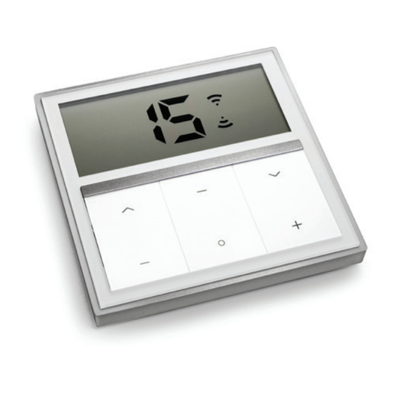
WALL SWITCH OVERVIEW
Please read prior to installation and use. Save these instructions for future reference.
BUTTON INSTRUCTIONS
LCD Display
LCD Display
Up
Up
Down
Down
Lower Channel
Lower Channel
Higher Channel
Higher Channel
Stop
Group Control
Group Control
Stop
P1 Button
LED
light
P1 button
Lithium Battery Switch
HORIZONTAL
ROLLER / SHEER
BLIND
DUAL / WOVEN
TILT MOTOR
MOTOR
REPLACING THE BATTERY
a. Unscrew with the screwdriver then gently press down the cover.
b. Install battery (CR2430) with positive (+) side facing up.
c. Gently assemble the cover back and replace screw with screwdriver.
a.
b.
ADVANCED SETTING - DISABLE LIMIT SETTING
a. Press and hold "Stop" button more than 15s.
Action on
Wall Switch will show "L" (lock).
Wall Switch
b. In the next 10s, press one "P2" button on
the back of Wall Switch. Wall Switch will show
Wall Switch
Response
"o", then the Wall Switch switches to "Lock"
mode to disable the following commands:
Action on
- Change Motor Direction
Wall Switch
- Setting the Upper and Lower Limit
- Adjust Limit
- Roller Mode or Sheer Mode
Wall Switch
Response
c. Press and hold "Stop" button more than 15s.
Wall Switch will show "U" (unlock).
d. In the next 10s, press one "P2" button on
the back of Wall Switch. Wall Switch will show
Action on
"o". The Wall Switch now switches to "Unlock"
Wall Switch
mode, you can access all control functions.
*This advanced feature is intended to be used
Wall Switch
after all shade programming is completed. User
Response
Mode will prevent accidental or unintended
changing of limits.
P2
P2
P2
P2
Power line
P1 Button
Signal line
HONEYCOMB
CELLULAR
MOTOR
c.
a.
Stop
b.
P2 Button
c.
d.
P2 Button
Stop
Advertisement
Table of Contents

Summary of Contents for ALTA BLISS SURFACE MOUNTED WALL SWITCH
- Page 1 WALL SWITCH OVERVIEW DECLARATIONS Please read prior to installation and use. Save these instructions for future reference. U.S. Radio Frequency FCC Compliance This device complies with Part 15 of the FCC Rules. Operation is subject to the following two BUTTON INSTRUCTIONS conditions: (1) This device may not cause harmful interference, and (2) This device must accept any interference received, including interference that may cause...
- Page 2 SET LOWER LIMIT Action on CHANNEL OPTIONS 6. ROLLER MODE AND SHEER MODE Wall Switch a. Press “Down” button to lower Down Down Stop the shade, then press “Stop” button ROLLER SHADE MODE -Default Action on SELECT A CHANNEL Action on when it is in the desired lower limit.
Need help?
Do you have a question about the BLISS SURFACE MOUNTED WALL SWITCH and is the answer not in the manual?
Questions and answers