
Summary of Contents for BA SYSTEMS BAS 918S
- Page 1 BAS 918S/929S Manual Manual BA Systems—Petershvilevej 1—DK-3200 Helsinge—http://www.basystems.dk...
-
Page 2: Table Of Contents
Basic Controller operation ..................66 Menu structure ..................... 66 Scheme selection ....................67 Scheme activation ....................68 Regulation mode ....................69 Scheme setup ...................... 70 Info Screen ......................72 Watch Screen ...................... 72 Setup for IP access ....................73 BA Systems—Petershvilevej 1—DK-3200 Helsinge—http://www.basystems.dk... -
Page 3: Introduction
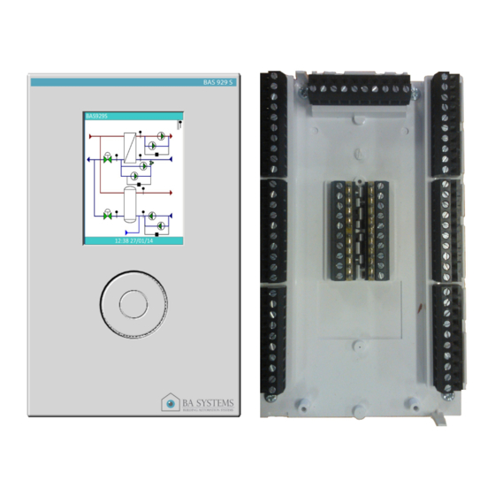
BAS 918S/929S Manual Introduction: Thank you for choosing a BAS 918S/929S controller. Please make sure that you have received the correct controller version and all the materials included. The difference between the two controllers are only the supported I/O. Please look at the following illustrations. -
Page 4: Materials Included
Produkt front 4 pcs. of , 3.9mm x 32 mm screws for wall mount Cable relief bracket for cable retention at socket 2 pcs. of 3.0mm x 8 mm screws for cable relief bracket mounting (4) BA Systems—Petershvilevej 1—DK-3200 Helsinge—http://www.basystems.dk... -
Page 5: Product Mount
Use a sharp knife to cut the plastic along or within the lines of the markings. When cutout is made in the connector end of the front, cables are inserted here and may be retained in the socket using the cable releif bracket. BA Systems—Petershvilevej 1—DK-3200 Helsinge—http://www.basystems.dk... -
Page 6: Installation
Generic socket connections are defined in placement and function in the following draw- ings and descriptions. This indicates the maximum I/O configuration for the BAS9XXS controller. Please note that the variant you have bought may have reduced configuration. BA Systems—Petershvilevej 1—DK-3200 Helsinge—http://www.basystems.dk... - Page 7 BAS 918S/929S Manual Controller profile: BA Systems—Petershvilevej 1—DK-3200 Helsinge—http://www.basystems.dk...
- Page 8 BAS 918S/929S Manual Controller front: Dimensions for wall mount are indicated from above drawing. BA Systems—Petershvilevej 1—DK-3200 Helsinge—http://www.basystems.dk...
-
Page 9: Terminals Description
Protected against reverse polarity and as indicated by + and – signs. input voltages up to 40V. Capability per I/O number: Channel 1..10: 0-1600 ohm (PT1000) Channel 1,3,5,7,9,10: 0/2-10V Channel 9,10:0/4-20 mA DC Channel 9,10:0..44900 ohm (NTC) BA Systems—Petershvilevej 1—DK-3200 Helsinge—http://www.basystems.dk... -
Page 10: Functional Description
Please see visualization below. Circulation Pump BAS9XXS CONTROLLER DOXB DOXA "DO" RELAY CONNECTED HAS 0-10V 1V DROP OVER THE TERMINALS DO2B DO2A D01B D01A Circulation Pump BAS9XXS CONTROLLER DOXB DOXA 24VAC/DC 0-10V DO2B DO2A D01B D01A SECONDARY RELAY BA Systems—Petershvilevej 1—DK-3200 Helsinge—http://www.basystems.dk... - Page 11 An advantage of this is that there is only one common reference. As shown above, a 5 wire cable is sufficient for connection to 4 pcs of thermal sensors. Please note though, that sensor calibration is recommended because of increased voltage drop over the common reference. BA Systems—Petershvilevej 1—DK-3200 Helsinge—http://www.basystems.dk...
- Page 12 + analog input wire. Example, connecting Pressure Transmitter: 24V SUPPLY BAS9XXS CONTROLLER PRESSURE TRANSMITTER TERMINALS 24VAC/DC AI(X)- AI(X)+ 0-10V 4-20mA SUPPLY CONNECTED AT THE LOAD, TO AVOID DISTURBING THE ANALOG MEASUREMENT BA Systems—Petershvilevej 1—DK-3200 Helsinge—http://www.basystems.dk...
- Page 13 INPUTS AND ANALOG OUTPUTS ARE CONNECTED IN THE CONTROLLER, SO ONE REFERENCE WIRE IS SUFFICIENT Stepmotor output ports Is not available on the current versions of the BAS9XXS controllers. Please contact the supplier for more information. BA Systems—Petershvilevej 1—DK-3200 Helsinge—http://www.basystems.dk...
-
Page 14: Option Module Connection
BUS- for configu- ration mode) -24V B (MINUS) BUS - NET B (BUS MINUS) Bus interfaces with differential signaling (all except MBUS) must use twisted pair cabling. One pair for a bus interface, RS485, KNX or LON. BA Systems—Petershvilevej 1—DK-3200 Helsinge—http://www.basystems.dk... -
Page 15: Modbus
The controller is always using BACnet port BAC0/47808 and is given the name BAS9XXS Device. The controller ID can be configured by the menu system, operated through the scroll button. The ID is by default set to 1. BA Systems—Petershvilevej 1—DK-3200 Helsinge—http://www.basystems.dk... -
Page 16: Bas918S Configuration
BAS 918S/929S Manual BAS 918S configuration: BA Systems—Petershvilevej 1—DK-3200 Helsinge—http://www.basystems.dk... -
Page 17: Bas929S Configuration
BAS 918S/929S Manual BAS 929S configuration: BA Systems—Petershvilevej 1—DK-3200 Helsinge—http://www.basystems.dk... -
Page 18: Scheme List
The list below defines available schemes: Central heating Central heating and Hot water tank Central heating with Heat Exchanger Central heating with Heat Exchanger and Hot water tank Dual Central heating Dual Central heating with Heat Exchanger BA Systems—Petershvilevej 1—DK-3200 Helsinge—http://www.basystems.dk... -
Page 19: Scheme Introduction
Water metering in the following control scemes is optional. Scheme selection therefore includes of water metering ”on” or ”off” selection. Symbol description Symbol Description Flow meter Modulation control valve Outdoor temperature sensor Gate valve Pump Temperature sensor Hot water tank with temperature sensor Heat exchanger Pressure transmitter BA Systems—Petershvilevej 1—DK-3200 Helsinge—http://www.basystems.dk... -
Page 20: Scheme 1, Central Heating
BAS 918S/929S Manual Scheme 1, process diagram: Central heating (CH) BAS918S or BAS929S BA Systems—Petershvilevej 1—DK-3200 Helsinge—http://www.basystems.dk... - Page 21 Motor valves will often have a common terminal for NUL and Analog reference (-). If so AO÷ and NUL must be connected. Water metering scaling to be defined when selecting controlling scheme. Above wiring assumes that the components Circulation pump and Motor valve is to be supplied by 240VAC. BA Systems—Petershvilevej 1—DK-3200 Helsinge—http://www.basystems.dk...
- Page 22 Water metering scaling to be defined when selecting controlling scheme. 24VAC as well as 24VDC may be used as supply. Above wiring assumes that Circulation pump and Motor valve is selected to support the same supply as the controller. BA Systems—Petershvilevej 1—DK-3200 Helsinge—http://www.basystems.dk...
- Page 23 These are all default values that may be changed Default activation: The circulation pump is activated once every 24 hours if no other regulation is detected. The valve for regulation is likewise activated once every 24 hours if no other regulation is de- tected. BA Systems—Petershvilevej 1—DK-3200 Helsinge—http://www.basystems.dk...
- Page 24 Status (0:Stop, 1:Manuel, 2:Auto run, 3:Auto stop) Energy state (0:Auto, 1:Vinter, 2:Force start, 3:Force stop, 4:Day/off, 5:Night/off) Values measured Out door sensor temperature Forward temperature Not used (returns 0) Return temperature Motor valve position i percent Pump Stop/Start BA Systems—Petershvilevej 1—DK-3200 Helsinge—http://www.basystems.dk...
- Page 25 Energy state (0:Auto, 1:Vinter, 2:Force start, 3:Force stop, CV1_SV_stat 4:Day/off, 5:Night/off) Values measured _CV1_TC901 Out door sensor temperature _CV1_TC301 Forward temperature _CV1_TC401 Return temperature _EMPTY_ Not used (returns 0) _CV1_MV401 Motor valve position i percent _CV1_CP301 Pump Stop/Start BA Systems—Petershvilevej 1—DK-3200 Helsinge—http://www.basystems.dk...
-
Page 26: Scheme 2, Central Heating And Hot Water Tank
BAS 918S/929S Manual Scheme 2, process diagram: Central heating (CH) and Hot water tank (HWT) Centralvarme blandesløjfe med varmtvandsbeholder BAS918S or BAS929S BA Systems—Petershvilevej 1—DK-3200 Helsinge—http://www.basystems.dk... - Page 27 Motor valves will often have a common terminal for NUL and Analog reference (-). If so AO÷ and NUL must be connected. Water metering scaling to be defined when selecting controlling scheme. Above wiring assumes that the components Circulation pump and Motor valve is to be supplied by 240VAC. BA Systems—Petershvilevej 1—DK-3200 Helsinge—http://www.basystems.dk...
- Page 28 Water metering scaling to be defined when selecting controlling scheme. 24VAC as well as 24VDC may be used as supply. Above wiring assumes that Circulation pump and Motor valve is selected to support the same supply as the controller. BA Systems—Petershvilevej 1—DK-3200 Helsinge—http://www.basystems.dk...
- Page 29 These are all default values that may be changed Default activation The circulation pump is activated once every 24 hours if no other regulation is detected. The valve for regulation is likewise activated once every 24 hours if no other regulation is detected. BA Systems—Petershvilevej 1—DK-3200 Helsinge—http://www.basystems.dk...
- Page 30 01.00 until 70°C Tank temperature is reached or until 03.00 o’clock. All setpoints/timers may be adjusted in the controlling scheme parameters. Circulation pump The Hot water circulation pump is controlled by a real time clock based timer for start / stop. BA Systems—Petershvilevej 1—DK-3200 Helsinge—http://www.basystems.dk...
- Page 31 Status (0:Stop, 1:Manuel, 2:Auto run, 3:Auto stop) Energy state (0:Auto, 1:Vinter, 2:Force start, 3:Force stop, 4:Day/off, 5:Night/off) Central Heating/Values measured Out door sensor temperature Forward temperature Not used (returns 0) Return temperature Motor valve position i percent Pump Stop/Start BA Systems—Petershvilevej 1—DK-3200 Helsinge—http://www.basystems.dk...
- Page 32 7:Saturday, 8:All days Return limiter forced set point Pump state (0:Off, 1:On) Status (0:Stop, 1:Dag, 2:Nat, 3:Legionella) Hot Water Tank/Values measured Tank temperature Return temperature (if selected) Circulation temperature Motor valve position in percent Pump state (0:Off, 1:On) BA Systems—Petershvilevej 1—DK-3200 Helsinge—http://www.basystems.dk...
- Page 33 Energy state (0:Auto, 1:Vinter, 2:Force start, 3:Force stop, CV1_SV_stat 4:Day/off, 5:Night/off) Central Heating/Values measured _CV1_TC901 Out door sensor temperature _CV1_TC301 Forward temperature _CV1_TC401 Return temperature _EMPTY_ Not used (returns 0) _CV1_MV401 Motor valve position i percent _CV1_CP301 Pump Stop/Start BA Systems—Petershvilevej 1—DK-3200 Helsinge—http://www.basystems.dk...
- Page 34 Pump state (0:Off, 1:On) VB1_s Status (0:Stop, 1:Dag, 2:Nat, 3:Legionella) Hot Water Tank/Values measured _VB1_TC301 Tank temperature _VB1_TC401 Return temperature (if selected) _VB1_TC402 Circulation temperature _VB1_MV401 Motor valve position in percent _VB1_CP401 Pump state (0:Off, 1:On) BA Systems—Petershvilevej 1—DK-3200 Helsinge—http://www.basystems.dk...
-
Page 35: Scheme 3, Central Heating With Heat Exchanger
BAS 918S/929S Manual Scheme 3, process diagram: Central heating with Heat Exchanger BAS918S or BAS929S BA Systems—Petershvilevej 1—DK-3200 Helsinge—http://www.basystems.dk... - Page 36 Motor valves will often have a common terminal for NUL and Analog reference (-). If so AO÷ and NUL must be connected. Water metering scaling to be defined when selecting controlling scheme. Above wiring assumes that the components Circulation pump and Motor valve is to be supplied by 240VAC. BA Systems—Petershvilevej 1—DK-3200 Helsinge—http://www.basystems.dk...
- Page 37 Water metering scaling to be defined when selecting controlling scheme. 24VAC as well as 24VDC may be used as supply. Above wiring assumes that Circulation pump and Motor valve is selected to support the same supply as the controller. BA Systems—Petershvilevej 1—DK-3200 Helsinge—http://www.basystems.dk...
- Page 38 These are all default values that may be changed Default activation The circulation pump is activated once every 24 hours if no other regulation is detected. The valve for regulation is likewise activated once every 24 hours if no other regulation is detected. BA Systems—Petershvilevej 1—DK-3200 Helsinge—http://www.basystems.dk...
- Page 39 Status (0:Stop, 1:Manuel, 2:Auto run, 3:Auto stop) Energy state (0:Auto, 1:Vinter, 2:Force start, 3:Force stop, 4:Day/off, 5:Night/off) Values measured Out door sensor temperature Forward temperature Not used (returns 0) Return temperature Motor valve position i percent Pump Stop/Start BA Systems—Petershvilevej 1—DK-3200 Helsinge—http://www.basystems.dk...
- Page 40 Energy state (0:Auto, 1:Vinter, 2:Force start, 3:Force stop, CV1_SV_stat 4:Day/off, 5:Night/off) Central Heating/Values measured _CV1_TC901 Out door sensor temperature _CV1_TC301 Forward temperature _CV1_TC401 Return temperature _EMPTY_ Not used (returns 0) _CV1_MV401 Motor valve position i percent _CV1_CP301 Pump Stop/Start BA Systems—Petershvilevej 1—DK-3200 Helsinge—http://www.basystems.dk...
-
Page 41: Scheme 4, Central Heating With Heat Exchanger And Hot Water Tank
BAS 918S/929S Manual Scheme 4, process diagram: Central heating with heat exchanger and hot water supply BAS918S or BAS929S BA Systems—Petershvilevej 1—DK-3200 Helsinge—http://www.basystems.dk... - Page 42 Motor valves will often have a common terminal for NUL and Analog reference (-). If so AO÷ and NUL must be connected. Water metering scaling to be defined when selecting controlling scheme. Above wiring assumes that the components Circulation pump and Motor valve is to be supplied by 240VAC. BA Systems—Petershvilevej 1—DK-3200 Helsinge—http://www.basystems.dk...
- Page 43 Water metering scaling to be defined when selecting controlling scheme. 24VAC as well as 24VDC may be used as supply. Above wiring assumes that Circulation pump and Motor valve is selected to support the same supply as the controller. BA Systems—Petershvilevej 1—DK-3200 Helsinge—http://www.basystems.dk...
- Page 44 These are all default values that may be changed Default activation The circulation pump is activated once every 24 hours if no other regulation is detected. The valve for regulation is likewise activated once every 24 hours if no other regulation is de- tected. BA Systems—Petershvilevej 1—DK-3200 Helsinge—http://www.basystems.dk...
- Page 45 01.00 until 70°C Tank temperature is reached or until 03.00 o’clock. All setpoints/timers may be adjusted in the controlling scheme parameters. Circulation pump The Hot water circulation pump is controlled by a real time clock based timer for start / stop. BA Systems—Petershvilevej 1—DK-3200 Helsinge—http://www.basystems.dk...
- Page 46 Status (0:Stop, 1:Manuel, 2:Auto run, 3:Auto stop) Energy state (0:Auto, 1:Vinter, 2:Force start, 3:Force stop, 4:Day/off, 5:Night/off) Central Heating/Values measured Out door sensor temperature Forward temperature Not used (returns 0) Return temperature Motor valve position i percent Pump Stop/Start BA Systems—Petershvilevej 1—DK-3200 Helsinge—http://www.basystems.dk...
- Page 47 7:Saturday, 8:All days Return limiter forced set point Pump state (0:Off, 1:On) Status (0:Stop, 1:Dag, 2:Nat, 3:Legionella) Hot Water Tank/Values measured Tank temperature Return temperature (if selected) Circulation temperature Motor valve position in percent Pump state (0:Off, 1:On) BA Systems—Petershvilevej 1—DK-3200 Helsinge—http://www.basystems.dk...
- Page 48 Energy state (0:Auto, 1:Vinter, 2:Force start, 3:Force stop, CV1_SV_stat 4:Day/off, 5:Night/off) Central Heating/Values measured _CV1_TC901 Out door sensor temperature _CV1_TC301 Forward temperature _CV1_TC401 Return temperature _EMPTY_ Not used (returns 0) _CV1_MV401 Motor valve position i percent _CV1_CP301 Pump Stop/Start BA Systems—Petershvilevej 1—DK-3200 Helsinge—http://www.basystems.dk...
- Page 49 Pump state (0:Off, 1:On) VB1_s Status (0:Stop, 1:Dag, 2:Nat, 3:Legionella) Hot Water Tank/Values measured _VB1_TC301 Tank temperature _VB1_TC401 Return temperature (if selected) _VB1_TC402 Circulation temperature _VB1_MV401 Motor valve position in percent _VB1_CP401 Pump state (0:Off, 1:On) BA Systems—Petershvilevej 1—DK-3200 Helsinge—http://www.basystems.dk...
-
Page 50: Scheme 5, Dual Central Heating
BAS 918S/929S Manual Scheme 5, process diagram: Dual Central heating BAS918S or BAS929S BA Systems—Petershvilevej 1—DK-3200 Helsinge—http://www.basystems.dk... - Page 51 Motor valves will often have a common terminal for NUL and Analog reference (-). If so AO÷ and NUL must be connected. Water metering scaling to be defined when selecting controlling scheme. Above wiring assumes that the components Circulation pump and Motor valve is to be supplied by 240VAC. BA Systems—Petershvilevej 1—DK-3200 Helsinge—http://www.basystems.dk...
- Page 52 Water metering scaling to be defined when selecting controlling scheme. 24VAC as well as 24VDC may be used as supply. Above wiring assumes that Circulation pump and Motor valve is selected to support the same supply as the controller. BA Systems—Petershvilevej 1—DK-3200 Helsinge—http://www.basystems.dk...
- Page 53 These are all default values that may be changed Default activation The circulation pump is activated once every 24 hours if no other regulation is detected. The valve for regulation is likewise activated once every 24 hours if no other regulation is detected. BA Systems—Petershvilevej 1—DK-3200 Helsinge—http://www.basystems.dk...
- Page 54 Status (0:Stop, 1:Manuel, 2:Auto run, 3:Auto stop) Energy state (0:Auto, 1:Vinter, 2:Force start, 3:Force stop, 4:Day/off, 5:Night/off) Centarl Heating circuit 1/Values measured Out door sensor temperature Forward temperature Not used (returns 0) Return temperature Motor valve position i percent Pump Stop/Start BA Systems—Petershvilevej 1—DK-3200 Helsinge—http://www.basystems.dk...
- Page 55 Status (0:Stop, 1:Manuel, 2:Auto run, 3:Auto stop) Energy state (0:Auto, 1:Vinter, 2:Force start, 3:Force stop, 4:Day/off, 5:Night/off) Centarl Heating circuit 2/Values measured Out door sensor temperature Forward temperature Not used (returns 0) Return temperature Motor valve position i percent Pump Stop/Start BA Systems—Petershvilevej 1—DK-3200 Helsinge—http://www.basystems.dk...
- Page 56 Energy state (0:Auto, 1:Vinter, 2:Force start, 3:Force stop, CV1_SV_stat 4:Day/off, 5:Night/off) Central Heating circuit 1/Values measured _CV1_TC901 Out door sensor temperature _CV1_TC301 Forward temperature _CV1_TC401 Return temperature _EMPTY_ Not used (returns 0) _CV1_MV401 Motor valve position i percent _CV1_CP301 Pump Stop/Start BA Systems—Petershvilevej 1—DK-3200 Helsinge—http://www.basystems.dk...
- Page 57 Energy state (0:Auto, 1:Vinter, 2:Force start, 3:Force stop, CV2_SV_stat 4:Day/off, 5:Night/off) Central Heating circuit 2/Values measured _CV2_TC901 Out door sensor temperature _CV2_TC301 Forward temperature _CV2_TC401 Return temperature _EMPTY_ Not used (returns 0) _CV2_MV401 Motor valve position i percent CV2_CP301 Pump Stop/Start BA Systems—Petershvilevej 1—DK-3200 Helsinge—http://www.basystems.dk...
-
Page 58: Scheme 6, Dual Central Heating With Heat Exchanger
BAS 918S/929S Manual Scheme 6, process diagram: Dual Central heating with Heat Exchanger BAS918S or BAS929S BA Systems—Petershvilevej 1—DK-3200 Helsinge—http://www.basystems.dk... - Page 59 Motor valves will often have a common terminal for NUL and Analog reference (-). If so AO÷ and NUL must be connected. Water metering scaling to be defined when selecting controlling scheme. Above wiring assumes that the components Circulation pump and Motor valve is to be supplied by 240VAC. BA Systems—Petershvilevej 1—DK-3200 Helsinge—http://www.basystems.dk...
- Page 60 Water metering scaling to be defined when selecting controlling scheme. 24VAC as well as 24VDC may be used as supply. Above wiring assumes that Circulation pump and Motor valve is selected to support the same supply as the controller. BA Systems—Petershvilevej 1—DK-3200 Helsinge—http://www.basystems.dk...
- Page 61 These are all default values that may be changed Default activation The circulation pump is activated once every 24 hours if no other regulation is detected. The valve for regulation is likewise activated once every 24 hours if no other regulation is detected. BA Systems—Petershvilevej 1—DK-3200 Helsinge—http://www.basystems.dk...
- Page 62 Status (0:Stop, 1:Manuel, 2:Auto run, 3:Auto stop) Energy state (0:Auto, 1:Vinter, 2:Force start, 3:Force stop, 4:Day/off, 5:Night/off) Central Heating circuit 1/Values measured Out door sensor temperature Forward temperature Not used (returns 0) Return temperature Motor valve position i percent Pump Stop/Start BA Systems—Petershvilevej 1—DK-3200 Helsinge—http://www.basystems.dk...
- Page 63 Status (0:Stop, 1:Manuel, 2:Auto run, 3:Auto stop) Energy state (0:Auto, 1:Vinter, 2:Force start, 3:Force stop, 4:Day/off, 5:Night/off) Values measured circuit 2 Out door sensor temperature Forward temperature Not used (returns 0) Return temperature Motor valve position i percent Pump Stop/Start BA Systems—Petershvilevej 1—DK-3200 Helsinge—http://www.basystems.dk...
- Page 64 Energy state (0:Auto, 1:Vinter, 2:Force start, 3:Force stop, CV1_SV_stat 4:Day/off, 5:Night/off) Central Heating circuit 1/Values measured _CV1_TC901 Out door sensor temperature _CV1_TC301 Forward temperature _CV1_TC401 Return temperature _EMPTY_ Not used (returns 0) _CV1_MV401 Motor valve position i percent _CV1_CP301 Pump Stop/Start BA Systems—Petershvilevej 1—DK-3200 Helsinge—http://www.basystems.dk...
- Page 65 Energy state (0:Auto, 1:Vinter, 2:Force start, 3:Force stop, CV2_SV_stat 4:Day/off, 5:Night/off) Central Heating circuit 2/Values measured _CV2_TC901 Out door sensor temperature _CV2_TC301 Forward temperature _CV2_TC401 Return temperature _EMPTY_ Not used (returns 0) _CV2_MV401 Motor valve position i percent CV2_CP301 Pump Stop/Start BA Systems—Petershvilevej 1—DK-3200 Helsinge—http://www.basystems.dk...
-
Page 66: Basic Controller Operation
PIN code shown Is Scheme Restart selected ? Scheme now active/ Regulation running Scheme selection Scheme setup 3-point PID Scheme 1 Scheme 2 Analog PID Restart Use return limiter Scheme 3 Cancel Scheme 6 BA Systems—Petershvilevej 1—DK-3200 Helsinge—http://www.basystems.dk... -
Page 67: Scheme Selection
The actual schemes supported are shown and detailed in the previous sections. Central heating Central heating and hot water Double Central heating With the “Central heating” scheme selected, the following sections will show setup and operation. BA Systems—Petershvilevej 1—DK-3200 Helsinge—http://www.basystems.dk... -
Page 68: Scheme Activation
Enter one short push and the change is accepted. Finally scroll to the ”OK” position and push the button. The selections will now be saved into the scheme and regulation will be active. BA Systems—Petershvilevej 1—DK-3200 Helsinge—http://www.basystems.dk... -
Page 69: Regulation Mode
Besides from the “Info” and “Clock” screen, menu mode will show all data available for the active regulation scheme and enable any configuration option. In the following, all menu screens will be shown and described in details. BA Systems—Petershvilevej 1—DK-3200 Helsinge—http://www.basystems.dk... -
Page 70: Scheme Setup
Submenu “Actual” is shown below as an example: Central heating/actual Outdoor temperature 12.8 °C Flow temp. 42.2 °C Return temp. 31.4 °C Flow temp. Ref. 42.0 °C Return temp. limitation 51.4 °C Valve 12:38 11/08/13 BA Systems—Petershvilevej 1—DK-3200 Helsinge—http://www.basystems.dk... - Page 71 The code is “5555”. This will further enable change of passwords and the ability to create new users or modify rights for existing users. Misc. Setup/Manual control Manual control: °C Off time: 4320 min 12:38 11/08/13 To terminate and exit, execute a long push on the scroll wheel. BA Systems—Petershvilevej 1—DK-3200 Helsinge—http://www.basystems.dk...
-
Page 72: Info Screen
This menu allow settings of current time, GMT offset, Daylight saving time on/off, date for- mat, Controller language, and finally the screen saver activation time in minutes. BAS918S Time: 11:38 11/8/13 Setup: GMT Offset: Auto DST: Date format: DD/MM/YY Language: Screensaver: 12:38 11/08/13 BA Systems—Petershvilevej 1—DK-3200 Helsinge—http://www.basystems.dk... -
Page 73: Setup For Ip Access
For mobile units a web browser and a dedicated application must be installed. The following operating systems are supported - Windows - Linux - MAC OS - Android The Android application is downloaded from the BA Systems WEB page using the link http://www.basystems.dk/Tools/Releases/Android/BAS_Web_Client.apk BAS918S DHCP: Active Static TCP/IP setup: TCP/IP address: 192.168.1.251...
Need help?
Do you have a question about the BAS 918S and is the answer not in the manual?
Questions and answers