Table of Contents
Advertisement
Quick Links
Advertisement
Table of Contents

Summary of Contents for Per Vices Crimson TNG
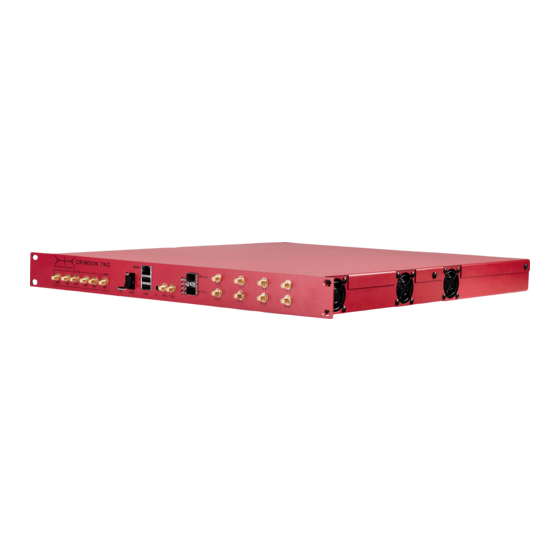
- Page 1 CRIMSON TNG USER MANUAL PER VICES CORPORATION...
-
Page 2: Table Of Contents
Contents Contents Change Log ..........Preface . -
Page 3: Contents
Hardware Set Up ......... 37 Crimson TNG Network Configuration ......38 Network Set Up: Host PC Management IP Address . - Page 4 CONTENTS 9 Updating Crimson TNG MCU Firmware ......... . 57 Automatic MCU Update Pre-requisites .
-
Page 5: Change Log
CONTENTS Change Log Date and Revision Notes 2016-05-02: Rev A: Initial Release 2016-05-18: Rev B: Populating Specifications 2016-07-12: Rev C: Update System Architecture Section and Diagrams 2016-09-22: Rev D: Update Top Level and Digital Board Architecture Diagrams 2016-10-20: Rev E: Include SMA Torque Specifications 2016-12-08: Rev F: Update Installation and Configuration Chapter 2017-06-12: Rev G: Update Networking section to include instructions on how to update Crimson IP address... -
Page 6: Preface
Preface Crimson TNG Crimson TNG is a high performance, wide band, high gain, direct conversion quadrature software defined radio transceiver and signal processing platform. It has four channels, each comprised of independent receive and transmit blocks, capable of processing up to 325MHz of instantaneous RF bandwidth from DC to 6.8GHz and synchronized using a JESD204B subclass 1 link to ensure... - Page 7 This product provides a sophisticated platform capable of advanced RF Signal processing and includes a robust and fully integrated RF chain. Our hope is that you will find Crimson TNG to be a useful and dependable companion in your engineering, development, and research efforts.
-
Page 8: Disclaimer
Vices neither assumes nor authorizes any person to assume for it any other liability. Use of this device is at your own risk. Per Vices shall not be liable for any damages, direct or indirect, incurred or arising from the use of this product. In no event will Per Vices be liable for loss of profits, loss of use, loss of data, business interruption, nor for punitive, incidental, consequential,... -
Page 9: Warnings
CONTENTS Warnings WARNING RISK OF ELECTRIC SHOCK Do not attempt to modify or touch the internals of this device. Ensure host computer is properly grounded during operation. Disconnect AC power during installing or removal. WARNING HOT SURFACE This device may become very hot during operation; avoid contact. Ensure adequate ventilation and that unobstructed fan inlets. -
Page 10: Specifications And Interfaces
Table 1.1: Absolute Ratings: Exposure or sustained operation at absolute ratings may permanently damage Crimson TNG. Ensure fan inlets (located on both sides of the device) are not blocked during operation. -
Page 11: Observed Performance
1. SPECIFICATIONS AND INTERFACES Observed Performance Crimson TNG is a very flexible radio and signal processing platform that supports high bandwidth communications over a wide tuning range. The hardware and signal processing capabilities may be configured to support a very wide variety of applications, each with their own figures of merit. It is, therefore, fairly challenging to provide uniform performance specifications across those different... - Page 12 1. SPECIFICATIONS AND INTERFACES Table 1.2: Observed Performance. These specifications reference observations taken during internal use and development. Calibration Measurements relative to 20˚C Specification Units Common Radio RF Stage (ADF4355) 6800 Baseband Stage Dynamic Range SFDR Receive Radio RF Input Power Noise Figure, Rx RF St Power Gain High...
-
Page 13: External Interfaces
1. SPECIFICATIONS AND INTERFACES External Interfaces Crimson TNG has a number of user accessible interfaces through which the device can connect to external sources and sinks. Management functions are carried out over a web page hosted by the Crimson TNG transceiver and accessible using the Management Ethernet port on the front face of the device. -
Page 14: Operating System
If you have any questions or concerns about optical fibre requirements, please do not hesitate to contact us. Mechanical Crimson TNG conforms to a 1U form factor and 19-inch+ rack. A mechanical diagram is included in Chapter 10. There is a significant difference between a 10GBASE-X interface (4 serial lanes specified to 3.125Gbps using 8b/10b coding), and the 10GBASE-R interface (1 serial lane specified to 10.3125Gbps using 64b/66b coding) that... -
Page 15: Rf Chain
1. SPECIFICATIONS AND INTERFACES RF Chain Simulated RF chain performance (based on component specifications) yield the simulated perfor- mance indicated in Table 1.3. As both the receive and transmission chains use variable stages, the figures were calculated using midpoint references for attenuation and gain stages. With proper tuning and calibration, you should expect better values. -
Page 16: System Architecture
System Architecture Overview Crimson TNG uses a highly modular design consisting of five boards. Each board is connected using shielded, high speed cabling to support its operation (Figure 2.1). The power board provides power to the digital, time, receive (Rx), and transmit (Tx) boards. The digital board provides an interface to control, configure, and send/receive data to/from the receive (Rx), transmit (Tx), and... -
Page 17: Power Distribution
FPGA (Figure 2.3 on the next page). The ARM (HPS) portion of the board hosts the web server through which Crimson TNG can be configured, and a UART serial port, which is used to communicate with the Rx, Tx, and time modules. A separate high speed link allows serial data to be shared directly between the Rx and Tx boards and the FPGA fabric. -
Page 18: Time Board
Figure 2.3: Digital board system block diagram. Time Board Clock distribution on the Crimson TNG transceiver is fairly robust. The internal reference source is an oven-controlled crystal oscillator (OCXO) that provides a very stable (5ppb) and accurate 10MHz signal and may be tuned using the AD5624R nanoDAC. A single ended external reference clock may also be used, provided it meets the input swing requirements listed on the specifications... - Page 19 2. SYSTEM ARCHITECTURE A buffered copy of the 100MHZ VCXO output is also provided to a second LMK04828, through a second HMC 988. The buffered output drives the second PLL of the second LMK04828 and provides clocking to all frequency synthesizers for each front end channel. A buffered output of the analog reference signal is also provided (Ext.PLL) and a buffered copy of the original 100MHz reference signal is available on Ext.
-
Page 20: Receive Board Radio Chain
2. SYSTEM ARCHITECTURE Receive Board Radio Chain The Crimson TNG receive board consists of a radio front end terminating with the Texas In- struments dual channel ADC16DX370 analog-to-digital converter, as shown in Figure 2.6. This architecture is duplicated four times, once for each channel. -
Page 21: Fpga Dsp Chains
2. SYSTEM ARCHITECTURE FPGA DSP Chains A simplified illustration of the DSP chains for transmit (Figure 2.8) and receive (Figure 2.9) provides a broad outline of the FPGA processing from the SFP+ ports to the converters. CORDIC Deframing VITA/Trig FIFO Resampler Mixer SFP+... - Page 22 2. SYSTEM ARCHITECTURE bandwidth on those channels is 81.25MHz. It is possible to obtain the full 325MSPS bandwidth on all four output channels with custom firmware, however, this limits the number of available receive channels. If your application demands full bandwidth on each channel, please contact us and we can provide you with custom firmware.
-
Page 23: System Operation
System Operation Flow Control and Start of Burst This section addresses some of the mechanisms behind flow control and start of burst. The current code requires the temporal variance between the Host PC and Crimson to be less than 20ppm/s for convergence to be achieved. On non-realtime operating systems, operating at the highest sample rates, it is sometimes the case that this error may vary under load the system performs differently, which causes us to occasionally lose convergence. -
Page 24: Latency
3. SYSTEM OPERATION 3. You start streaming data, and achieve steady state. At this point, your host PC is sending radio data in UDP packets at uniform intervals, which are being re-transmitted by the switch. 4. The Crimson transmission sample buffer holds steady at 85% - the default value which helps provide sufficient margin for start of burst, and damp out any routine fluctuations. -
Page 25: Receive Or Transmit Latency
3. SYSTEM OPERATION Receive or Transmit Latency This measurement concerns itself with measuring the time elapsed from when an signal incident on the antenna is processed and presented to the user. Alternatively, it is the time elapsed from when a user application sends radio samples, to the time those samples are transmitted over the antenna. Various sources contribute to this latency, including the radio chain, converters, FPGA DSP, pack- etization, buffering, network transmission latency, and OS receive latency. - Page 26 3. SYSTEM OPERATION pkt,bytes (3.4) τ de f rame f ramesize c,nw Given that Crimson uses complex samples of 32 bits each, S = 4, and the Ethernet framer smpl,size is 64 bits, S = 8, with a network clock of f = 156.25M Hz , and the default specified f ramesize c,nw...
- Page 27 This table provides ping statistics over a point-to-point connection between a host PC and Crimson for various packet counts, using an Emulex Corporation NIC, a default Crimson TNG image, and the populated with the results of: ping -f -c <N> <Address>, where N is the number of packets (as an integer), and Address corresponds to the destination IP address.
-
Page 28: Round Trip Latency
3. SYSTEM OPERATION Of course, this poses a very substantial and critical problem: The transmission of radio data requires a tightly coupled and synchronous data flow in order to effectively represent arbitrary wave forms. When we run out of user data to transmit to the DAC (ie: we are in an underflow condition), we therefore need to insert samples into the data stream to ensure specified performance , and to provide a well defined mode of operation. - Page 29 3. SYSTEM OPERATION kernel), using the latest kernel drivers (to ensure optimal network card performance), and proces- sor and core affinity provide the most immediate benefit. In addition, purchasing a network card optimized for low latency applications provides additional benefit. Lower latency applications may benefit from a modified stock image that uses a low latency IP core, and reduces sample buffer size - please contact us directly for more information.
-
Page 30: Triggers
Nonstandard option The stock Crimson TNG product does not provide hardware support for per-channel triggers; though this section discusses both global and per-channel triggers, for per-channel trigger operation, please contact us for a hardware upgrade to your Crimson TNG product that enables per-channel trigger support. -
Page 31: Global Trigger Sensitivity
Per Channel (U.Fl) Triggers Nonstandard Option The default Crimson TNG unit does not expose per channel triggers; please contact us for more information on this optional hardware upgrade. Per Channel triggers operate similarly to the global trigger, except that there is one unique trigger per radio channel. -
Page 32: Trigger Parameter Summary
4. TRIGGERS Trigger Parameter Summary fpga/trigger/ sma_dir sma_pol rx/{a,b,c,d}/trigger/ edge_sample_num edge_backoff sma_mode trig_sel ufl_dir ufl_mode ufl_pol tx/{a,b,c,d}/trigger/ edge_sample_num edge_backoff gating sma_mode trig_sel ufl_dir ufl_mode ufl_pol Trigger Parameter Descriptions The following provides a more detailed description of all the trigger parameters. sma_dir Path state/fpga/trigger/sma_dir... -
Page 33: Edge_Sample_Num
4. TRIGGERS and the triggered state by VCC (active high). If the value is "negative", then the trigger shall be reversed (active low). NOTE: The trigger input has a fixed, weak, pull-up. The polarity is set using FPGA logic. This means that you must actively sink the trigger input to GND for proper operation during blanking periods;... -
Page 34: Trig_Sel
Description Trigger mode associated with U.Fl channel trigger ports. Nonstandard Option The default Crimson TNG unit does not expose per channel triggers; please contact us for more information on this optional hardware upgrade. Additional Information This specifies whether the U.Fl per channel triggers should be edge or level sensitive, and operates identically to the sma_mode property, except that trigger behaviour is specific and exclusive to the specified radio channel. -
Page 35: Ufl_Dir
Description Specifies direction of Per Channel U.Fl Trigger port, with respect to the FPGA. Nonstandard Option The default Crimson TNG unit does not expose per channel triggers; please contact us for more information on this optional hardware upgrade. Additional Information This property works similarly to the sma_dir property, except it is channel specific. -
Page 36: Ssh
4. TRIGGERS You can directly set the trigger behaviour through the Crimson state tree. The state tree is located in /var/crimson/state. The relative path to one of the specified properties is specified above. You may also get and set selected properties through UHD. Example code demonstrating this functionality is available in the UHD repository. -
Page 37: Installation And Configuration
4. Connect 10G SFP+ cables from 10GBASE-R network card installed in host computer to SFP+ ports on front of Crimson TNG. 5. Turn on the unit and wait for the LEDs on the front of Crimson TNG to light up. -
Page 38: Crimson Tng Network Configuration
Figure 5.2: Physical installation of Crimson hardware. Crimson TNG Network Configuration Crimson TNG boasts three network ports: there is a dedicated management port, and two data ports. Each port must be correctly configured to ensure proper operation, as indicated in Figure... - Page 39 A and C sent over SFP+ A, and channels B and D sent over SFP+ B, as illustrated in Figure 5.4. The default network values are listed in Table 5.1. A recommended client networking configuration is shown in Table 5.2. Table 5.1: Default Crimson TNG Interface Addresses, Including UDP Destination Ports for SFP+ Headers. SFP+ Interfaces...
- Page 40 IP: Data Port B Port: 42827 Figure 5.4: Default networking set up for Crimson TNG. The destination IP addresses for receive ports may be modified using the web GUI. The default configuration sees information from Rx A sent to the destination IP address of 10.10.10.10.
-
Page 41: Network Set Up: Host Pc Management Ip Address
You can reconfigure the IP address and host name by clicking on the «Debug» tab of the home page. You can also SSH into Crimson TNG with user name root. By default, there is no password set up. -
Page 42: Network Set Up: Host Pc Sfp+ Ip Addresses
7. Click OK To confirm that you have successfully configured the Management port, type 192.168.10.2 into your web browser. If you have successfully configured the IP, you will be taken to the Crimson TNG web UI shown in Figure 5.5. -
Page 43: Build Per Vices Libuhd Driver And Install Gnu Radio
GNU Radio that has been compiled with the Ettus libUHD version. Ensuring that you have correctly installed the Per Vices libUHD version, and then recompiling GNU Radio ensures consistency in the library versions and fixes any errors. - Page 44 Detailed instructions, including the dependencies, are available at: http://files.ettus.com/manual/page_build_guide.html Note: In order to use Crimson TNG with UHD, you must download the Per Vices UHD version as it contains all the required modifications needed to support the Per Vices drivers.
- Page 45 $ make install Install GNURadio Once you have installed Per Vices libUHD, you must obtain a version of GNU Radio. If you are not familiar with git, make, and various build flow, we suggest you use the latest release: http://GnuRadio.org/releases/GnuRadio/ You should be able to use the gnuradio version associated with your distribution, though you will have to ensure that you use the Per Vices UHD version in lieu of the distribution provided version.
- Page 46 5. INSTALLATION AND CONFIGURATION Enter the GnuRadio directory, and checkout to an appropriate release version. Here, we use v3.7.13.4 $ cd GnuRadio $ git checkout v3.7.13.4 Initialize and update the VOLK submodule, ensuring you choose the same tag as gnuradio: $ git submodule init $ git pull --recurse-submodules=on origin v3.7.13.4 $ git submodule update...
- Page 47 files WILL cause problems down the road; either move them somewhere else, or delete them. 4. Download the Per Vices UHD driver sources code, and compile and install it. a) For compatability, you may want to use the “-DCMAKE_INSTALL_PREFIX=/usr” cmake flag to install binaries to /usr (this is consistent with most linux distributions).
-
Page 48: Network Set Up: Modifying Crimson Management Ip Address
5. INSTALLATION AND CONFIGURATION 4. Remove the default gnuradio variant: ./pybombs recipes remove gr-recipes 5. Create a new prefix for pv; ./pybombs prefix init /home/<username>/pybombs/pervices -a pervices 6. Build UHD using: ./pybombs -p pervices install –static uhd gnuradio38 7. When prompted, please CONFIRM that you are installing libuhd from source. The above steps should allow you to successfully install UHD using pybombs and from the Per Vices repositories. -
Page 49: Ping Test
5. INSTALLATION AND CONFIGURATION Ping test This is the most basic test and serves to check if a route exists between your host computer and the specified IP address. Assuming the management IP address is W.X.Y.Z, then you can run this test by typing;... -
Page 50: Add New Management Ip Address
5. INSTALLATION AND CONFIGURATION second time without. In a correct configuration, with a single Crimson device, you should be able to automatically find the device without specifying the address. To run this test, and assuming the management IP address is W.X.Y.Z, type the following; [host_pc]$ uhd_find_devices --args ’addr=W.X.Y.Z’... -
Page 51: Removing Management Ip Address
5. INSTALLATION AND CONFIGURATION the new management port, then to run uhd_find_devices, and uhd_usrp_probe, and then to run a simple GNUradio script that is known to work - and ensuring that you have also applied your final, intended, configuration on the host computer as well. Removing Management IP address CAREFULLY TEST CHANGES TO NETWORK PARAMETERS, AND ENSURE FUNCTIONALITY, PRIOR TO MAKING THESE... -
Page 52: Led Sequence
Once you write to this file, the changes will be applied on the next reboot. LED Sequence When Crimson TNG is powered on, the four status LEDs next to the SD card will begin to light up. A normal LED sequence is shown in Figure 5.12. -
Page 53: Use And Operation
UHD drivers, and also provides a web interface. You may also directly configure the device over SSH. The device can be configured using the Per Vices UHD drivers. This allows for easy interface with software devices, and provides some compatibility with USRP devices. -
Page 54: Crimson Tng Device Data Format
Crimson TNG Device Data Format Crimson TNG uses complex, signed, 32-bit integers to communicate data over the SFP+ ports. Data Format Data are transmitted in IQ pairs. Each IQ pair is 32 bits, with the I and Q components represented by two 16 bit signed integers. -
Page 55: Troubleshooting
Troubleshooting Table 8.1 on the next page shows some of the common problems you may encounter when first configuring Crimson TNG. The default UHD installation includes a diagnostic program, called, “crimson_diagnostic.sh”, that checks your host system for various common misconfigurations, and reports them. This functionality can aid troubleshooting and initial set up. - Page 56 <BROADCAST, MULTICAST, UP, LOWER_UP> Confirm you have configured the correct network interface. If the Crimson TNG MGMT port does not respond to ping, try configuring a different network interface with the settings listed in Table 5.2 on page 40.
-
Page 57: Updating Crimson Tng
2. A client terminal with SSH and SCP installed. Automatic MCU Update Procedure 1. Copy the firmware binaries over to Crimson TNG, and place them within the /home/root/pv_mcu directory. If you are using the default configuration and wish to update all the MCUs, you can use the following scp invocation: cd <firmware_directory>... -
Page 58: Manual Mcu Update Pre-Requisites
9. UPDATING CRIMSON TNG 2. Once you have copied the MCU binaries, you must program them. This is done from within Crimson TNG. Accordingly, you need to SSH into the machine, then run the MCU update routine located in the /home/root/pv_mcu directory: ssh root@192.168.10.2... - Page 59 file to the boot loader, and subsequently carries out another memory operation (-U) to set the fuses to (fuse2:w:0xBF:m). 4. Congratulations! You have successfully updated the Crimson TNG MCU firmware. Remember to confirm that you are burning the correct boot loader firmware file to the correct board!
-
Page 60: Fpga Firmware
Figure 9.1: A sample Atmel Programmer. FPGA Firmware The FPGA firmware used by Crimson TNG is stored on the provided Crimson TNG SD card and is loaded onto the FPGA during boot. This procedure describes how to replace or update the FPGA code stored on the SD card. -
Page 61: Fpga Update Procedure
filename of soc_system.rbf. The SD Card shipped with your Crimson TNG platform. 3. Mini SD Card Reader All Crimson TNG transceivers ship with a USB card reader. Alternatively, you may use your own. 4. A computer to copy over the SD Card. - Page 62 You must ensure you cleanly unmount the partition. You risk corrupting the firmware image (and possibly even Crimson TNG) if you simply remove the USB key without first unmounting (safely removing) the USB key! For added security, type «sync» to flush file system buffers prior to removing the SDCard.
-
Page 63: Fpga Signal Tap
9. UPDATING CRIMSON TNG Figure 9.3: FPGA JTAG header location on digital board. You may use this jumper to attach a USB Blaster 2 device on to Crimson TNG, which enables you to use Signal Tap or carry out JTAG searches. -
Page 64: Crimson Tng Mechanical
Crimson TNG Mechanical... - Page 65 P e r V i c e s C o rp o ra t i o n TX D TX C TX B TX A SFP+B RX D RX B RX A RX C TRIG Figure 10.1: Crimson TNG Mechanical...
Need help?
Do you have a question about the Crimson TNG and is the answer not in the manual?
Questions and answers