Table of Contents
Advertisement
Advertisement
Table of Contents

Summary of Contents for MicroP XRF-2000 Series
- Page 1 Operating MANUAL For XRF-2000 Series Rev. 5.12 December 26, 2012...
- Page 2 XRF-2000 Series Operating Manual...
- Page 3 XRF-2000 Series Operating Manual IMPORTANT – PLEASE READ THIS FIRST! COPYRIGHT○ c 2011 MicroP Co., Ltd. ALL RIGHT RESERVED PLEASE READ CAREFULLY THE OPERATION AND APPROPRIATE MAINTENANCE INSTRUCTIONS IN THIS MANUAL BEFORE ATTEMPTING TO OPERATE THE EQUIPMENT. NOTWITHSTANDING MICRO PIONEER’S LIMITED WARRANTY,...
-
Page 4: Table Of Contents
3.1.3 Exit ..................21 3.2 Display ..................... 21 3.3 Cal ....................22 3.4 Etc ....................23 3.5 MicroP Co., Ltd................. 23 4. Main Toolbar 4.1 System Configuration ............... 25 4.2 Set Limit ................... 25 4.3 SET Measuring Time ................ 25 4.4 View Statistic Window .............. - Page 5 XRF-2000 Series Operating Manual 4.9.2 2D(Point)................47 4.9.3 3D(Scan)................48 4.9.4 3D(Point) ................48 4.10 Random Stage................49 4.11 Set Measuring Unit................. 49 4.12 Set Decimal Point................50 4.13 Cal File Select Window ..............50 4.14 Recalibration Window ..............
-
Page 6: Introduction
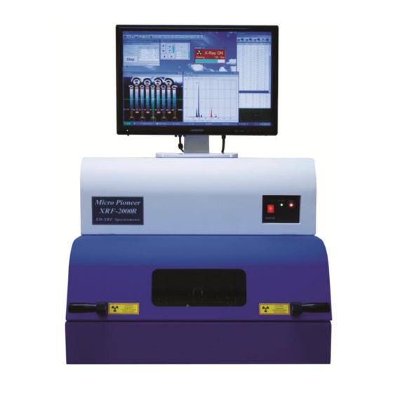
XRF-2000 systems are designed to measure the thickness of multi coating elements or detect the elements in analyzed samples and determine their concentrations using X-Ray fluorescence (XRF). The analysis performed by XRF-2000 series can by divided into three categories: Thickness measurement – measure the thickness of multilayer coating ... -
Page 7: Principles Of Operation
XRF-2000 Series Operating Manual 1.2 Principles of Operation XRF-2000 Series systems utilize the phenomenon that when a sample is irradiated with x-ray radiation, the sample’s atoms are excited. As the atoms return to their stable state, they emit x-ray photons (X-ray Fluorescence –... -
Page 8: Typical Specification
XRF-2000 Series Operating Manual liquid or thin film form; or even be a few layers of elements plated on a thick base substrate. In most cases, samples are analyzed with minimal preparations. 1.3 TYPICAL SPECIFICATIONS Input Power 115/220 VAC, 50/60Hz, 150W (maximum) Typically 220VAC 0.5A... - Page 9 XRF-2000 Series Operating Manual...
-
Page 10: System Operation
XRF-2000 Series Operating Manual 2. System Operation 2.1 Safety Considerations Standard Procedures All standard safety procedures for operating electrical machinery should apply to spectrometers of this series. Each system is intended to be operated only as indicated in its Operation Manual. -
Page 11: Radiation Safety
XRF-2000 Series Operating Manual 2.2 Radiation Safety XRF-2000 Series equipment is intrinsically safe from radiation hazards. Every machine is inspected prior to its delivery, ensuring that level of radiation anywhere around the sample chamber is not higher than the ambient radiation in the free environment. The instruments are equipped with safety magnetic switches to ensure that proper shielding is in place during x-ray operation, avoiding a possibility of exposure to radiation. -
Page 12: Software Installation
Make sure your computer is correctly connected and then turn on the monitor and computer. XrayV5 is software of XRF-2000 series and updated periodically. You can download it from MicroP Co., Ltd. web site www.micropioneer.com. The system has its own storage device as USB memory. When the system is connected to computer, USB memory will be your hard disk which is named XRF-2000. -
Page 13: Drive Installation
XRF-2000 Series Operating Manual 2.5 Drive Installation 2.5.1 Connect System to Computer System Power On and connect system to computer through the USB cable. Then “Found New Hardware window will be displayed as below. Cancel all windows for driver installation and make sure if your system disk drive recognized as follow. -
Page 14: Install Drivers
XRF-2000 Series Operating Manual 2.5.2 Install Drivers Go to Control Panel System Device Manager There are two uninstalled drivers, USB device which is EZ Cap (Video Capture Card) and XRF-2000 which are USB serial converter and USB serial port. - Page 15 XRF-2000 Series Operating Manual Click Next will install the driver for USB serial converter. After installing the driver you can see the USB Serial Converter in Device Manager as bellow. Right Click again on XRF-2000 and “Update drive software”.
- Page 16 XRF-2000 Series Operating Manual Finally you can see the USB Serial Converter and USB Serial Port in Device Manager as below; Right Click on USB Device and “Update drive software”. Click Browse Icon and select E:\XRayV5\Driver\EzCap directory.
-
Page 17: To Increase System Speed
XRF-2000 Series Operating Manual 2.5.3 To Increase System Speed Quit the XRayV5 program. Go to Control panel -> System -> Device Manager -> Ports (COM & LTP) -> USB Serial Port -> Properties -> Port Settings -> Advanced and change Latency time to 2 as follows. -
Page 18: Running Xrf-2000 Software
XRF-2000 Series Operating Manual 2.5 Running XRF-2000 software ① Turn on the XRF-2000 Series Machine. ② Turn on the computer (if not already done) and click the XrayV5 icon on the desk top to active XrayV5. ③ Enter Password “t” and click on the opening message. -
Page 19: File Menu
XRF-2000 Series Operating Manual 3.1 File Menu 3.1.1 Config window Menu 1 Focus Laser: Control brightness of laser on Camera Window Excel (Open Office is available in public) Send Data: ON/OFF data transfer to Excel. Excel file must be opened prior to data transfer. -
Page 20: Administrator Login
XRF-2000 Series Operating Manual Menu2 Z down when door open: Enable Z axis down to specified distance when door is opened. Auto focus (Only flat Sample): Enable automatic focus prior to start measurement. Stage control direction: Dir. Stage moves stage same direction with stage control direction. -
Page 21: Exit
XRF-2000 Series Operating Manual Main window & Main toolbar : Re Calibration, New Calibration, Measuring correction, Density correction menus are enabled when administrator Login. Select Cal File : Delete Cal File and comment on Cal File are enabled when administrator is logged in. -
Page 22: Cal
XRF-2000 Series Operating Manual 3.3 Cal Description of function is described in Chapter 4 except following. Measuring Correction : Make user correction Gain=1 Offset=0 is default value which means measuring correction is not effected to result. -
Page 23: Etc
XRF-2000 Series Operating Manual 3.4 Etc Description of function is described in Chapter 4 except the following. Auto cycle interval: Input Auto cycle interval time. The interval time is measuring time plus rest time. 3.5 MicroP Co., Ltd. Display Micro Pioneer company information, Software version and System... -
Page 24: Main Toolbar
XRF-2000 Series Operating Manual 4. Main Toolbar Laser Focus, Send to Excel, Change Password, Program Mode Set control limit of Result Set measuring time Display statistic window Display Spectrum windows Display Camera window Display Stage control window Display Periodic Table window Display 2D &... -
Page 25: System Configuration
XRF-2000 Series Operating Manual System Configuration Refer to chapter 3.1.1 Set Limit Lower : Lower limit value for Low Mode Upper : Upper limit value for Up Mode Mode Low : Measured data is bigger than 'Lower value' means good ... -
Page 26: View Statistic Window
XRF-2000 Series Operating Manual Clock Time≥ Preset Time Enter measuring time and click OK or press enter key. View Statistic Window Statistic Window displays thickness or concentration of samples and statistical information. Also provide a function of preview, print, user defined print form, adding comment and open/save file. -
Page 27: Print Menu
XRF-2000 Series Operating Manual 4.4.2 Print Menu Select a different type of print form such as UPA type, CMI type etc. Each menu has a preview mode, direct print mode and print to image mode. Set option report menu to fix the print form as one of the various. -
Page 28: Diff Block Menu
XRF-2000 Series Operating Manual 4.4.3 Diff Block Menu This Menu allows printing different applications’ results in same format on same paper. Select Cal file and analyze sample and drag result and Save, go another Cal file and analyze sample and drag result and Save. -
Page 29: Setup Menu
XRF-2000 Series Operating Manual 4.4.4 Setup Menu 4.4.4.1 Configuration All option for print form is able to define in configuration menu, such as customer name, company logo and others. - Page 30 XRF-2000 Series Operating Manual 4.4.4.2 Edit User Defined Print File 1) Open the Statistic Window The sequence of creating the user defined print form is Setup -> Edit user defined print file -> Save edited user defined print file -> Set user defined print file ->...
- Page 31 XRF-2000 Series Operating Manual The relation between setup table and hard copy of the user defined print file is as follows.
- Page 32 XRF-2000 Series Operating Manual The print position of X and Y means as follows.
- Page 33 XRF-2000 Series Operating Manual 3) Add/Delete Item ADD -Select item to add, specify print position and click Add Icon then save to user defined print file(*.UDP).
- Page 34 XRF-2000 Series Operating Manual Delete – Select item to delete and click Cut Icon then save to user defined print file(*.UDP). 4) Edit Item Edit – Select item to edit and change the print option such as position, color, Font and line width etc. and click Modi Icon then save to user...
- Page 35 XRF-2000 Series Operating Manual 5) Sample of User Print Form...
-
Page 36: Spectrum Window
XRF-2000 Series Operating Manual Spectrum window 4.5.1 Qualitative Analysis The objective of qualitative analysis is to identify the elemental component of unknown substances. The first step in qualitative analysis is spectra acquisition. Following spectra acquisition, the spectra must be manipulated and studied to best determine additional spectra acquisition and/or the qualitative answer desired. -
Page 37: Editing And Manipulating Spectra
XRF-2000 Series Operating Manual 4.5.2 Editing and Manipulating Spectra Automatic identification of peaks can be performed after spectra have been acquired. Click the Setup pull-down menu. Click Display element symbol in the Spectrum Window. Then the symbols of the elements will be displayed as follows;... - Page 38 XRF-2000 Series Operating Manual window display the possible element, channel, KeV and Data(CPS) as shown in above. The Green peak on right side is peak for Silver K-a(22.16KeV) but it is not identified automatically because the center of the sliver K-a moved to the left (called peak shift) as 21.96KeV. Therefore the...
- Page 39 XRF-2000 Series Operating Manual Clicking specific element shows its information such as Atomic number, Energy Value etc. and two vertical lines (blue lines) which is ROI low and ROI High are placed on the Spectrum window. Below is example of clicking...
- Page 40 XRF-2000 Series Operating Manual Click Right button shows menus to initialize, expend/reduce the vertical scale and reset to original spectrum.
-
Page 41: Camera Display Window
XRF-2000 Series Operating Manual Camera window Open/Save: Save sample image as bmp or jpg format. Copy: Copy sample image to clipboard. Start view: Start capturing sample image. Comment: Enter comment text to print. Print: Print sample image. -
Page 42: Sub Beam
XRF-2000 Series Operating Manual 4.6.1 Sub Beam: Generate multi indicator To change the camera window size, hold and drag right side or corner of the camera window. -
Page 43: Find Beam Center
XRF-2000 Series Operating Manual 4.6.2 Find Beam Center To find beam center, use below position reference. Click Find beam center on Camera Window. Place center of camera to Cu Part of the position reference and click Start. - Page 44 XRF-2000 Series Operating Manual Place center of camera to Sn Part of the position reference and click Start. Place center of camera to Cu Part of the position reference again and click Start. Place center of camera to border line between Cu and Sn of the position...
- Page 45 XRF-2000 Series Operating Manual When system finish to find the center of beam, make sure the vertical line coincide with border line between Cu and Sn. If does not, Go setup -> Adjust scale position. Adjust vertical line to border line between Cu and Sn. Click SET.
-
Page 46: Stage Control Window
XRF-2000 Series Operating Manual Stage Control Window Moving speed will be changed by the mouse operation. Left button is slow speed control. The speed will be changed by the clicked position. The inner position is slow speed and outer position is fast speed. Right button is fast speed control by using acceleration and deceleration method. -
Page 47: 3D Measure Window
XRF-2000 Series Operating Manual 2D&3D Measure Window 4.9.1 2D(Step) ex) 5 times analysis at intervals of 10mm from current position. Clicking direction starts to measure. Current Position 10mm Moving Direction 4.9.2 2D(Point) Move Sample to start position and Click Reg. Start Button. -
Page 48: Scan)
XRF-2000 Series Operating Manual 4.9.3 3D (Scan) No. of X meas. Point (4) X mm Y mm No. of Y Meas. Point (3) 4.9.4 3D (Point) Left Top Right Top Right Bottom Place camera position and cursor to left top and click Reg. Axis Button. -
Page 49: Random Stage
XRF-2000 Series Operating Manual 4.10 Random Stage Open/Save : Open/Save position data file. Set: Register the axis data. Space bar also works. Run: Start the measuring. Del: Clear all axis data. Ref: with saved position data, set ref.1 and 2 recalculate all other data. -
Page 50: Set Decimal Point
XRF-2000 Series Operating Manual 4.12 Set Decimal Point 4.13 Cal File Select Window Set: Use the selected cal file. Edit comment: Edit the comment of selected cal file. Delete: Delete the selected cal file. -
Page 51: Recalibration Window
XRF-2000 Series Operating Manual 4.14 Recalibration Window Recalibration procedure. 1) Manual axis calibration. - Set one calibration standard (ex: Au Inf.) on the stage. - Adjust position and focus. - Select desired (ex: Au Inf.) row on 'Calibration Data' window. -
Page 52: New Calibration
XRF-2000 Series Operating Manual 3) Click the Right button of mouse will be display the pop-up menu. View Spectrum: display standard’s spectrum on spectrum window.\ Clear selected CPS: Clear CPS for selected row data. Clear all CPS: Clear entire CPS in Cal data. - Page 53 XRF-2000 Series Operating Manual Double Click on Beam size, Meas Time and High Voltage, then Edit Cal. Mode window appears. Do as shown below. Select Cal. Mode which is just created. Target Dead time is 5% for Proportional Counter, 30% for PIN...
- Page 54 XRF-2000 Series Operating Manual New calibration will use pre-defined cal mode. Click Start Cal. button, and enter number of standard foil. Follow the message on New Calibration Window. Click OK to accept tube current.
- Page 55 XRF-2000 Series Operating Manual Load reference standard and click start. Example of Calibration : Enter or modify the thickness and composition value. Save new calibration.
-
Page 56: Quantitative Calibration
XRF-2000 Series Operating Manual 4.15..2 Quantitative Calibration Click icon for new calibration (ex: RoHs Plastic) Double Click on Beam size, Meas Time and High Voltage, then Edit Cal. Mode window appears. Do as shown below. - Page 57 XRF-2000 Series Operating Manual Select Cal. Mode which is just created. Target Dead time is 5% for Proportional Counter, 30% for PIN Diode detector. Click Start Cal. And check as below. Click OK.
- Page 58 XRF-2000 Series Operating Manual Enter number of standard sample Using around middle concentration of standard, get tube current by clicking Start. Click OK to accept tube current.
- Page 59 XRF-2000 Series Operating Manual Load reference standard and click start. Example of Calibration Enter or modify the composition value in green box. Display Resolution: change decimal point of Thickness, Concentration and CPS. Calibration Unit: Select concentration unit or specify unit ...
- Page 60 XRF-2000 Series Operating Manual After acquiring all standard, calibration curve must be reviewed and change calibration parameters to get a good result. Go to Setup -> Set condition in Cal data window. Method: Select Empirical or FP- The unknown sample spectrum is compared to that of standards and the spectrum most similar is used for estimating the unknown sample's composition.
- Page 61 XRF-2000 Series Operating Manual Remove sum peak: Sum, or pileup, peaks arise because two incoming x rays arrive at the pulse processor (amplifier) within a time frame that is less than the fast discriminator can detect the peak from the first event. This results in peaks that have energies with the sum of the two incoming x-ray events.
-
Page 62: Plating Bath Calibration
XRF-2000 Series Operating Manual 4.15.3 Plating Bath Calibration Click icon for new calibration on the tool bar (ex: Sn-Pb content in plating bath) Double Click on Beam size, Meas Time and High Voltage, then Edit Cal. Mode window appears. Do as shown below. Try to change numerical filter to get better... - Page 63 XRF-2000 Series Operating Manual Select Cal. Mode which is just created. Select biggest collimator and set measuring time as 100 sec. High Voltage must be adjusted regarding measuring element. Ex) ZnNi = 35KV, SnPb = 47KV New calibration will use pre-defined cal mode. Click Start Cal. button, and enter...
- Page 64 XRF-2000 Series Operating Manual Follow the message on New Calibration Window. Load SnPb infinity, Sn infinity, Pb infinity and general water in sample cup and click start step by step. Click OK to accept tube current.
- Page 65 XRF-2000 Series Operating Manual Load reference standard and click start. Example of Calibration : Enter or modify the composition value. Prepare Plating water standards as follows (Example). Plating water standards must be measured by AAS to verify its concentration. SnPb #1 = Sn 6g/L+Pb 1g/L...
- Page 66 XRF-2000 Series Operating Manual Sample Cup preparation (Substitution)
-
Page 67: System Adjustment Window
XRF-2000 Series Operating Manual 4.16 System Adjustment Window 4.16.3 General System Adjust is for positioning to the right energy location of the known peaks in KeV using Reference Standard which is contained Cu and Sn. Load Reference standard on the stage and adjust XY & focus. -
Page 68: Focus Laser
XRF-2000 Series Operating Manual 4.17 Focus Laser On/Off Focus Laser. 4.18 Lamp On/Off Lamp for Camera. 4.19 Set Y Stage Auto Move Analysis position moves to near door side when cover is opened and moves to analysis position automatically when cover is closed. -
Page 69: Maintenance
XRF-2000 Series Operating Manual 6. Maintenance Following these maintenance steps will insure normal and reliable operation of the system. This maintenance is intended to be performed by the operator. 1) Fan Filters Once a month clean the cabinet fan filter. - Page 70 XRF-2000 Series Operating Manual A further aid is to define the problem nature by the following criteria: 1. Is the problem always the same? 2. Does the problem appear at regular intervals or random intervals? The correct answers to many of the questions suggested above may not be an easy task, although the solution to many may be very simple.
-
Page 71: Appendix
XRF-2000 Series Operating Manual Appendix A. X-RAY FLUORESCENCE (XRF) When a primary x-ray excitation source from an x-ray tube or a radioactive source strikes a sample, the x-ray can either be absorbed by the atom or scattered through the material. The process in which an x-ray is absorbed by the atom by transferring all of its energy to an innermost electron is called the “photoelectric effect.”... - Page 72 XRF-2000 Series Operating Manual...
-
Page 73: New Calibration For Disk
XRF-2000 Series Operating Manual Appendix B New Calibration for Disk (V5 Version) Thickness Calibration (ex: NiP//Al) 1. On Main Window, Go File → Administrator Login → “t” → Enter. Click icon for new calibration on tools Bar and set as shown below. - Page 74 XRF-2000 Series Operating Manual 4. Click Button in the new Calibration Window to proceed. 5. Enter number of standard foil.
- Page 75 XRF-2000 Series Operating Manual 6. Follow the message in the New Calibration Window to get optimized Tube Current. 7. Click OK to accept optimized tube current.
- Page 76 XRF-2000 Series Operating Manual 8. Enter thickness value for each standard and load standard into chamber and click button in the new Calibration Window.
- Page 77 XRF-2000 Series Operating Manual Example of Calibration 9. Click button to save new calibration File.
- Page 78 XRF-2000 Series Operating Manual 10. Using Random Stage Recipe Click Random Stage on Tool Bar. Open position Data file. Click Pencil Icon. Click Car Icon to run.
-
Page 79: New Calibration For Rohs
XRF-2000 Series Operating Manual Appendix C New Calibration for RoHS_Plastic 1. Step Go File -> Administrator Login -> “t” -> O.K. Click icon for new calibration (ex: RoHs Plastic) Set acquisition parameters as shown below. - Page 80 XRF-2000 Series Operating Manual Load middle range concentration of standard samples. Click Auto set TC button, then system will show you optimized TC value. Click Add Step button. If you have another standard samples such as Cl (Halogen Free) which means multi-acquisition parameters, repeat again using different acquisition parameters.
- Page 81 XRF-2000 Series Operating Manual 2. Layer Click periodic table on tool bar and drag element to be analyzed into layer window. The final settings are as shown bellow.
- Page 82 XRF-2000 Series Operating Manual 3. Std Enter Standard Name for Layer 0 and Layer 1 as below. Click one of standard name and load standard sample in chamber the click Measuring Std.
- Page 83 XRF-2000 Series Operating Manual Repeat measuring for layer 1 as layer 0. 4. Intensity Finally check intensity for each layer as follows.
- Page 84 XRF-2000 Series Operating Manual 5. Save CAL File Enter Application Name and click Save to CalFile.
-
Page 85: Calibration For Csfp
XRF-2000 Series Operating Manual D. Calibration for CSFP This procedure is for unsatisfied FP result or new FP calibration. 1. Login and get Factory service On main window, go File -> Administrator Login -> “t” -> O.K. Place cursor on Main window and click the Main window then press Alt+Ctrl+Shif simultaneously and hold these keys and type “pioneerok”. - Page 86 B. Measuring spectrum Load FP Standard provided by MicroP Co., Ltd in to sample chamber. Add Step: Select acquisition parameter (PF, HV, TC, Col) and click Add Step.
- Page 87 XRF-2000 Series Operating Manual 4. Making Exc Click Periodic table and drag and drop elements into making EXC window. Enter Fit Line and Concentration. The FP standard composition is as follow.
- Page 88 XRF-2000 Series Operating Manual This table can be deleted line by line or all and saved or opened by right click of mouse. Click Do All file to create excitation files for all spectrum or click Do Selected File for specific spectrum.
Need help?
Do you have a question about the XRF-2000 Series and is the answer not in the manual?
Questions and answers