Table of Contents

Summary of Contents for proMtec u-ICC 2.45 compact
- Page 1 Erro! Use a guia Início para aplicar Überschrift 1 ao texto que deverá aparecer aqui. MICROWAVE CONCENTRATION MEASUREMENT µ-ICC 2.45 compact - MANUAL - S/N: A01-PG10-MAE Software version from V.0.21 Version No.: V3 2010-10-01...
-
Page 2: Table Of Contents
Erro! Use a guia Início para aplicar Überschrift 1 ao texto que deverá aparecer aqui. Safety instructions ........................3 Symbols and indices ......................3 Conventional usage......................3 General safety & warning notices ..................3 1.3.1 Environmental conditions ................... 4 1.3.2 Electrical treatments .................... - Page 3 Erro! Use a guia Início para aplicar Überschrift 1 ao texto que deverá aparecer aqui. 8.2.2 Deleting of configuration ..................30 8.2.3 Deleting of all memory ..................... 30 Moving of the measuring range ..................... 31 10 Troubleshooting ........................32 10.1 PIN is not working ......................
-
Page 4: Safety Instructions
Erro! Use a guia Início para aplicar Überschrift 1 ao texto que deverá aparecer aqui. 1 Safety instructions 1.1 Symbols and indices In this manual there are consecutive symbols used to indicate safety instructions. Warning possibility of danger for life and health Attention possibility of danger with light personal damages Notice... -
Page 5: Environmental Conditions
Erro! Use a guia Início para aplicar Überschrift 1 ao texto que deverá aparecer aqui. 1.3.1 Environmental conditions All components require non-corrosive environmental conditions while transporting, stocking and operating. 1.3.2 Electrical treatments The power supply must be interrupted during the installation and also for technical service to avoid getting in contact with energized parts. -
Page 6: System Description Μ-Icc 2.45 Compact
Another dependency is the distance between the sensor probes. Here it is important that the signal strength is quite enough to get from the transmitter to the receiver. Therefore proMtec offers the best fitting geometry for each special application. Receiver... - Page 7 Erro! Use a guia Início para aplicar Überschrift 1 ao texto que deverá aparecer aqui. • The microwave signal is conducted into the medium by the transmitter. The receiver collects the alleviated microwaves. • The reference signal has the typical propagation without any influences. It is used as a comparison with the alleviated microwave signal, to calculate a phase shift (decrease of propagation velocity) or an attenuation.
-
Page 8: Components
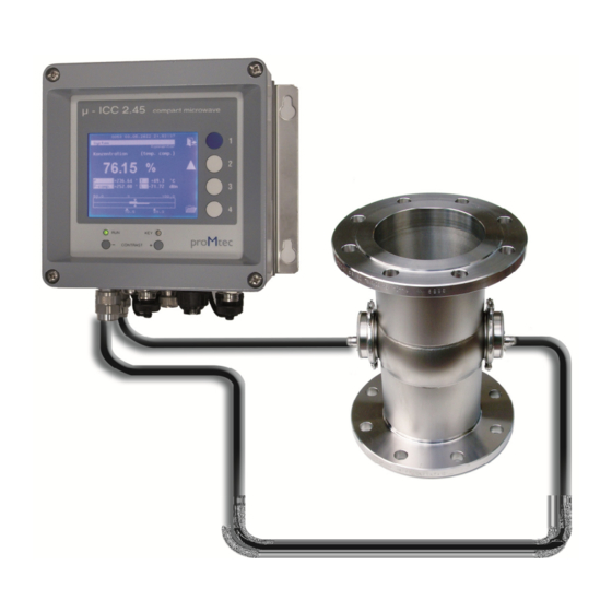
Erro! Use a guia Início para aplicar Überschrift 1 ao texto que deverá aparecer aqui. 2.2 Components The measuring system is composed of two components – the evaluation unit and the sensor probes. These probes are mounted into a pipe section (with flat sensor probes) or into a vessel (insertion sensor probes) and are connected via microwave cables with the evaluation unit. -
Page 9: Sensor With Probes
Erro! Use a guia Início para aplicar Überschrift 1 ao texto que deverá aparecer aqui. 2.2.2 Sensor with probes proMtec offers a great variety of sensor types. Depending on the several application proMtec designs the best fitting sensor type for implementing in your process without complexity. -
Page 10: Installation
Erro! Use a guia Início para aplicar Überschrift 1 ao texto que deverá aparecer aqui. 2.3 Installation 2.3.1 Installation of the Evaluation unit The device is delivered with a sub plate with four holding flaps (H x B = 120 x 180 mm for Ø... - Page 11 Erro! Use a guia Início para aplicar Überschrift 1 ao texto que deverá aparecer aqui. Connections: • Microwave cables: There are two identical microwave cables; one for the transmitter and one for the receiver. Both are connected with N-Plugs and it doesn’t mind, which one is used for the “T”-Plug respectively the “R”-Plug.
- Page 12 Erro! Use a guia Início para aplicar Überschrift 1 ao texto que deverá aparecer aqui. If you’re using an insertion sensor, by default there is a Pt 100 with two wire connection. In this case the plug-in is already bridged. If you want to connect your own two wired Pt 100 you have to bridge I2 with U2 and also I1 with U1, as you can see on the picture below.
- Page 13 Erro! Use a guia Início para aplicar Überschrift 1 ao texto que deverá aparecer aqui.
-
Page 14: Installation Recommendations
Erro! Use a guia Início para aplicar Überschrift 1 ao texto que deverá aparecer aqui. 2.4 Installation recommendations In order to get a reliable measurement it is necessary to have a good flow through the sensors. This ensures that there is no caking on the sensor probes. - Page 15 Erro! Use a guia Início para aplicar Überschrift 1 ao texto que deverá aparecer aqui. The best installation point is in the vertical pipe and enough away from the pump. The recommended distance away from the pump is 4 times of the diameter of the pipeline.
-
Page 16: Menu Topology And Operation Handling
Erro! Use a guia Início para aplicar Überschrift 1 ao texto que deverá aparecer aqui. 3 Menu topology and operation handling 3.1 Standard operation of the compact device The evaluation unit handles the data from the integrated microwave module. It displays different values on the screen such as the measurement, the Phase shift (raw and compensated), the temperature and the level. -
Page 17: Operation Via Pc Remote
• Errorstate: overview with error number in case of any problems • Service: only for maintenance by proMtec The several submenus are also explained more precisely in the following chapters. 3.2 Operation via PC Remote There is the option to operate the device via PC remote control. This is... - Page 18 If you ordered the compact device with blind cover, the software is already included. Otherwise the software is available on request. Therefore please get in contact with proMtec. Before the first start up make sure that there is .NET Framework version 3.5 or higher already installed on your system.
- Page 19 Erro! Use a guia Início para aplicar Überschrift 1 ao texto que deverá aparecer aqui. Now you get another different looking window, where the menus and submenus are shown in several tabs with the same structure like the device menu structure. To refresh the actual settings click on the button “data poll”, to take over the settings to the device click on the button “data assume”.
-
Page 20: First Start Up
Erro! Use a guia Início para aplicar Überschrift 1 ao texto que deverá aparecer aqui. 4 First Start Up Before connecting the evaluation unit with power supply, make sure that the microwave sensors already connected evaluation unit. With the first start up you should adjust basic settings; e.g. date and time. 4.1 Language SYSTEM / BASIS CONFIGURATION / LANGUAGE First of all you can choose the language from Deutsch, English, Francais, Italiano,... -
Page 21: Locking Keyboard
Nevertheless it is still possible to have a look on some of them. If you’ve lost the PIN number please get in contact with proMtec. 4.4.1 Changing PIN number Starting from „System” main menu, select „ Basis configuration” then chose „PIN-Nr. -
Page 22: Initial Sensor Configuration
If you’re not getting good results with the chosen measurement, please get in contact with proMtec. Starting from „ System” main menu, select „ Sensor” then „Measurement”. Now select e.g. „Phase measuring” and select „OK” and confirm it again by „OK”. -
Page 23: Measurement
Erro! Use a guia Início para aplicar Überschrift 1 ao texto que deverá aparecer aqui. 5.3 Measurement These settings are required to operate the measurement. 5.3.1 Temperature compensation SYSTEM / SENSOR / TEMP.COMPENSATION The microwave signal is influenced by temperature changes of the medium. In cause of this, the phase shift has to be temperature compensated. -
Page 24: Reference Point
Erro! Use a guia Início para aplicar Überschrift 1 ao texto que deverá aparecer aqui. Usually we take the maximal measurable value (with reserve) as A0. A1 is a microwaves absorption coefficient and depends on the distance between the probes. The measuring range appears on the display below the bargraph (drag pointer). -
Page 25: Other Settings
Erro! Use a guia Início para aplicar Überschrift 1 ao texto que deverá aparecer aqui. 5.4 Other Settings 5.4.1 Sensor Description SYSTEM / SENSOR / DESCRIPTION You should set a description of the measuring according to the application. Select „Description” and confirm by "OK" button. Select „Product name”, „Comment”, „Phys. -
Page 26: Data Logging
Erro! Use a guia Início para aplicar Überschrift 1 ao texto que deverá aparecer aqui. 6 Data logging There are two options to do data logging. By connecting a PC data can be recorded and stored directly on a hard disk drive. Alternatively the data can be stored on an internal SD card. -
Page 27: Usb Hid
Additionally there is the option to update the system software. In general this is only done by proMtec staff. For more details please get in contact with proMtec. For advices in installing and operating of the software read chapter “3.2 Operation via PC Remote”. -
Page 28: Calibrating
Erro! Use a guia Início para aplicar Überschrift 1 ao texto que deverá aparecer aqui. 7 Calibrating Before calibration it is important to set the initial sensor configuration (as it is described preliminary in chapter 5). Sampling For calibration it is necessary to take samples during the whole process and evaluate them in the laboratory. -
Page 29: Phase Correction With Level
Erro! Use a guia Início para aplicar Überschrift 1 ao texto que deverá aparecer aqui. The correlation coefficient R^2 should be nearly 1 proving that the sampling was representative and that the new coefficients can be entered in the evaluation unit. In the sheet „trend“, you can compare different settings graphically. -
Page 30: Sensor Settings: Save And Reload
Erro! Use a guia Início para aplicar Überschrift 1 ao texto que deverá aparecer aqui. 8 Sensor Settings: save and reload Here you can save and load your settings, and reload the factory settings. This can be done in the “Sensor” – section or in the “Memory allocation” – section. 8.1 Sensor: Save settings, Load settings, Factory settings SYSTEM / SENSOR / STANDARD SETTINGS 8.1.1 How to save configuration... -
Page 31: Deleting Of Configuration
Erro! Use a guia Início para aplicar Überschrift 1 ao texto que deverá aparecer aqui. 8.2.2 Deleting of configuration SYSTEM / MEMORY ALLOCATION / DELETE DATA SET Select the configuration to be deleted (1 to 30). Select „YES” button and finally confirm by „OK"... -
Page 32: Moving Of The Measuring Range
Erro! Use a guia Início para aplicar Überschrift 1 ao texto que deverá aparecer aqui. 9 Moving of the measuring range SYSTEM / SENSOR / CALIBRATION Sometimes the resulting measuring range is unsuitable for the measurement. There is a simple way to make it suitable. Example: There is a range from 65 to 90 %, but it is needed an upper limit of 95 %. -
Page 33: Troubleshooting
You can block the keyboard. Make sure, that third doesn’t know this PIN. If you don’t remember the PIN, please contact your supervisor. In emergency cases proMtec can override your PIN. 10.2 Constant offset SYSTEM / SENSOR / CALIBRATION / COEFFICIENT Maybe you will find a constant offset. -
Page 34: Technical Specifications
Erro! Use a guia Início para aplicar Überschrift 1 ao texto que deverá aparecer aqui. 11 Technical specifications Aluminium wall housing, protection IP65, Dimension 160 x 160 x Housing 120 mm, 3,1 kg Mounting 4 holding flaps H x B = 120 x 180 mm for ø 6 mm Power supply 24 V DC, max. -
Page 35: Spare Parts
Erro! Use a guia Início para aplicar Überschrift 1 ao texto que deverá aparecer aqui. 12 Spare parts Item Order number Evaluation unit µ-ICC 2.45 compact ICC CO LCD 3.9”-display 320 x 240 pixel with foil keyboard, ready to connect in wall housing cover 160 x 160 x 50 mm, A01-PG10-DIS connection cable Aluminium wall housing 160 x 160 x 70 mm, open without... -
Page 36: Declaration Of Conformity
Erro! Use a guia Início para aplicar Überschrift 1 ao texto que deverá aparecer aqui. 13 Declaration of Conformity... -
Page 37: Dimensional Drawings
Erro! Use a guia Início para aplicar Überschrift 1 ao texto que deverá aparecer aqui. 14 Dimensional drawings 14.1 Flat sensors with Inline-Gage DN 40 to 150... -
Page 38: Insertion Sensor Dn65
Erro! Use a guia Início para aplicar Überschrift 1 ao texto que deverá aparecer aqui. 14.2 Insertion sensor DN65... -
Page 39: Rinsed Insertion Sensor Dn65
Erro! Use a guia Início para aplicar Überschrift 1 ao texto que deverá aparecer aqui. 14.3 Rinsed insertion sensor DN65... -
Page 40: Insertion Sensor Dn80
Erro! Use a guia Início para aplicar Überschrift 1 ao texto que deverá aparecer aqui. 14.4 Insertion sensor DN80...
Need help?
Do you have a question about the u-ICC 2.45 compact and is the answer not in the manual?
Questions and answers