
Summary of Contents for RODI systems AquaLynx 250 RO-AC-ENC-V2
- Page 1 ® AquaLynx Model 250 RO-AC-ENC-V2 RO Controller Installation and Operating Manual 505-334-5865 ph 505-334-5867 fax www.rodisystems.com email: info@rodisystems.com 936 Highway 516 Aztec, NM 87410...
- Page 2 Copyright 2018 RODI Systems Corp. NOTICE This manual is protected by federal copyright laws. It should not be copied in any way, shape, or fashion without the written permission from RODI Systems Corp. Version 1.20 For product and service information: RODI Systems Corp.
- Page 3 Version History Version Date Effective Pages Description of Changes 1.00 02/12/18 Preliminary Issue 1.10 04/27/18 Initial Release Removed Reference to 1.20 12/04/18 Zero Temp Calibration...
- Page 4 Conventions and Symbols Special characters, listed and described below, are used in this documentation to emphasize certain information. Note: Emphasizes additional information pertinent to the subject matter. Warning: Emphasizes information about actions which may result in personal injury. Caution: Emphasizes information about actions which may result in equipment damage.
- Page 5 General Limited Warranty Warranty 1. In no event will RODI Systems Corp., or any of its representatives, be responsible or liable for indirect or consequential damages resulting from the use or application of any product. The user and those responsible for applying the product must satisfy themselves with the acceptability of the application.
-
Page 6: Table Of Contents
Table of Contents AL250-V2 Overview Introduction Features Specifications Outputs Inputs Mode Controls Expansion Port Serial Port Data Logging Installation Environmental Mounting Ground Connections Power Outputs Inputs Conductivity Modem Operation Controls Keypad LED Indicators Sequence Screens Main Menu Status Screen Quality Screen Alarm Log Settings Screen Settings Table... -
Page 7: Al250-V2 Overview
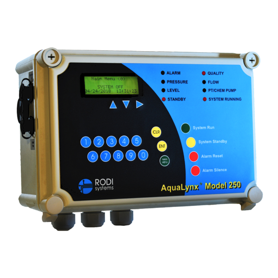
AL250-V2 Overview Introduction The AL250-V2 Reverse Osmosis Controller is designed to control and monitor the operating parameters of a single pump reverse osmosis water purification system. Information is displayed on a back-lit liquid crystal display, and on individual light- emitting diodes (LED). Functions and controls are operated through switches on the keypad. -
Page 8: Specifications
Specifications The AL250-V2 incorporates the following specifications: Power Requirements: The controller can operate with following primary voltages (acceptable range). Depending upon the voltage being used, the power must be wired to the proper position on the power terminal strip near the transformer. 115 VAC (108-130 VAC) Voltages outside of these values will damage 208 VAC (187-220 VAC) -
Page 9: Inputs
Low Supply Pressure Shutdown High Membrane Feed Pressure Shutdown High Feed Water Temperature Shutdown Low Salt Rejection Shutdown Output or Transformer Overload High Differential Pressure Shutdown (when using analog sensors) High Permeate Pressure Shutdown (when using analog sensors) High and Low Flow Recovery Shutdown (when using flow sensors) All 24 VAC outputs are protected by positive temperature coefficient resistors (polyfuses). -
Page 10: Mode
High Pressure Switch: This is a dry contact that signals the system to shut down if the pump discharge or membrane pressure exceeds the desired value. This is a normally open contact. When an open circuit condition exists between the two terminals, the system will operate. If contact is made between the two terminals, the system will shut down. -
Page 11: Controls
perform a flush as scheduled by the amount of time entered for “Flush Interval” in the Settings data entry screen (See “Settings” section of this manual). The Flush Interval is the number of minutes between flushes. The Flush Duration is the total time in seconds that unit flushes. During a flush, the inlet, autoflush, and diversion solenoid valves are open and the high pressure RO pump and chemical pump (if applicable) are both running. - Page 12 Expansion Port The AL250-V2 is equipped with one RS-485 expansion port which allows it to be networked into a larger water treatment monitoring system via Modbus RTU. The RS-485 expansion port is the 6 pin, watertight connector located in the upper right hand corner of the left hand side of the AL250-V2 enclosure.
-
Page 13: Expansion Port
Installation Environmental The AL250-V2 is equipped with a NEMA 4X enclosure for use in industrial environments subject to occasional exposure to water sprays and other wet conditions. The AL250-V2 should not be used in explosive environments. General environmental specifications are listed below. DO NOT mount controller in direct sunlight. -
Page 14: Ground
Ground A good common ground reference (earth ground) is essential for proper operation of the AL250-V2. A good earth ground or power circuit ground should be connected to the ground terminal block l on the enclosure backpanel. Connections Screw terminals are provided for making connections for sensor inputs and power. Sensor and I/O terminals are located on the inside of the door of the AL250-V2 enclosure. -
Page 15: I/O
The connections for the inputs and outputs are shown below. Avoid using excessively large wire (larger than 18 AWG) on the inputs and outputs since it may prevent the enclosure door from closing properly. All wires from the inputs and outputs must pass through the grommet in the cord seal. - Page 16 Alarm: This consists of a 108 db alarm horn mounted inside the AL250-V2 enclosure. A separate alarm output connection provides a dry relay contact rated on 2 amps. 26 28 30 32 AC or DC Power 2 Amps Max 25 27 29 31 24 VAC Common Incorrect Wiring...
-
Page 17: Inputs
Analog Pressure Inputs All inputs are designed for 4-20 mA isolated sensors. Excitation voltage to the sensors is supplied by the AL250-V2. Feed Pressure Sensor: This sensor monitors the pressure of the water being fed to the inlet of the pressure vessel array. Interstage Pressure Sensor: This sensor monitors the pressure of the water between the first and second stage arrays. - Page 18 F1 F2 F3 F4 F5 F6 F7 F8 F9 Discrete Inputs All inputs should be dry contacts rated for 24 VAC. Do not apply voltage to the inputs. Input voltage to the contacts is supplied by the AL250-V2. Low Pressure Switch: This is a dry contact that signals the system to shut down if the pump suction pressure falls below the desired value.
-
Page 19: Conductivity
level switch. The switch will stop the system at high level. When the level drops (the switch closes), the system will re-start after the “High Tank Startup Delay”, in minutes (See “Settings” section of this manual) that has been configured into the Settings data entry screen. The controller must be configured for one or two switch operation in the Settings menu (See “Settings”... -
Page 20: Operation
Operation Controls The AL250-V2 is housed in a NEMA 4X enclosure with a membrane keypad. Indicators include a 4 line x 20 character LCD with LED backlight and eight high intensity LED indicators for alarm conditions. The control features of the AL250-V2 are illustrated below. -
Page 21: Led Indicators
Alarm Silence: Pressing this key silences the alarm horn for 120 seconds. The system will still shut down if the alarm condition does not correct itself before the shutdown delay expires (See “Settings” section of this manual). Up Arrow, Down Arrow, Right Arrow: These keys are used to move through the display screens and for data entry purposes. -
Page 22: Screens
Startup Shutdown Open Inlet Valve Stop Pump and Chemical Feed Open Autoflush Valve Fifteen Second Delay (during autoflush sequence only) Open Permeate Divert Valve Close Inlet Valve Five Second Delay Close Autoflush Valve (if open) Start Chemical Feed Ten Second Delay Start Pump Close Auto Flush and Divert Valves (after the flush duration delay) -
Page 23: Settings Table
The second selection from the Settings Screen, number 1 key, allows the user to change the operating mode of the AL250-V2; Sanitize, Standby or Operating (Tank/Direct Feed) modes. The third selection, number 2 key, allows access to the Settings data entry screens. The user is prompted for the access code to enter sub menu 0 (Clock) or 2 (Settings) of the Settings screen (factory default access code = 12345). - Page 24 High Deadband (in deg C) through which the High Temp DB Temperature 0.1-10 temperature value must pass before the DegC Deadband high temperature alarm is released. High Delay (in seconds) before the high High Temp TD Sec Temperature 0-255 temperature alarm is activated once the Time Delay current value rises above the setpoint.
- Page 25 This setting allows the temperature sensor in the permeate conductivity cell Permeate to be calibrated to a known temperature Perm Temp Span Temperature 1-50 00.0 at span value. Only qualified users DegC Span following the procedures documented in Calibration the Calibration section of this manual should adjust this setting.
- Page 26 High Feed Delay (in seconds) before the system High Fd Prss Pressure Shut 0-255 shuts down after the high pressure alarm Shtdwn Down Delay is activated. High Permeate Pressure setpoint (in psig) which High Prm Prss SP 0-100 Pressure activates the high pressure alarm. Setpoint High Deadband (in psig) through which the...
- Page 27 This setting configures the use of the Configuration second flow sensor. Enter [0] to use the Flw2 Config of Flow 0 or 1 sensor on reject or [1] to use the sensor Sensor 2 on permeate. K Factor for K factor (in pulses per gallon) for the first Flw1 K Fact 0-10,000 0000.0...
-
Page 28: Diagnostic Screens
Diagnostic Screens From the Main Menu <1> screen, the user may select a number of diagnostic screens. The following may be accessed from the Main Diagnostic screen: Press “1” to view the serial number of the controller, software version, and serial port status. -
Page 29: Time Delays
3-10 Time Delays Time delays and deadbands are used to control the action of the AL250-V2 alarms. These are described below. Alarm is Released When Rising Process Value Exceeds Setpoint Plus Deadband Deadband Low Alarm Setpoint Time Delay Alarm Activates at End of Time Delay Time The illustration above shows the action of a low alarm setpoint on a falling value. -
Page 30: Calibration
Calibration Introduction A number of parameters monitored by the AL250-V2 must be periodically calibrated for optimum performance and accuracy. These are outlined below. AL250-V2 Calibration Settings Recommended Parameter Method of Calibration Index Calibration Number Frequency Calibration with Conductivity One to Three Feed Conductivity Standard Solution Months Depending... -
Page 31: Troubleshooting
Important Please note: Temperature and conductivity are combined in one sensor. If temperature and conductivity are both being calibrated, always calibrate the temperature first. Be careful not to damage (avoid excessive twisting, bending, etc.) the sensor leads when removing the sensor from the pipe fitting. Never reuse standard solutions. -
Page 32: Troubleshooting
If temperature and conductivity are both being calibrated, always calibrate the temperature first. Be careful not to damage (avoid excessive twisting, bending, etc.) the sensor leads when removing the sensor from the pipe fitting. The conductivity standard solution may be used for temperature calibration when ... - Page 33 Troubleshooting The AL250-V2 Reverse Osmosis Controller is designed for ease of maintenance and minimum service. Since the highest quality of electronic semiconductor components are used in this design, it is not likely that circuit malfunctions or failures will occur. It is our experience that field failures which most frequently occur are: ...
- Page 34 When the product tank is full the “Level” The product tank is full in Tank mode. LED is on and the RO will not run until the level drops below the switch. The level switch is set as closed when The tank level switch must be installed product tank is full.
- Page 35 Review the raw analog values in the diagnostic screens. The RTD values must be less than 4050. Open circuit in temperature sensor. Check the resistance across the red and green wires of BOTH sensors. acceptable range is 1000 – 1187 Ohms. Conductivity reading is erratic.
- Page 36 Faulty pressure switch. Test pressure switch. The AL250-V2 displays a low suction pressure alarm even though the suction The AL250-V2 requires a closed circuit to pressure is OK. Switch not wired properly. indicate low suction pressure. Check wiring.
- Page 38 Appendix B - Technical Bulletins Transient Surge Suppression Since its introduction, a number of the AL250-V2 units have been damaged by transient voltages. Units damaged by transient voltages may exhibit the following symptoms: Unit will not power-up, discrete inputs show ON and then OFF with no switch contact change, conductivity and/or temperature values bounce significantly or do not change at all, keypad buttons do not work, and unit displays odd alarms or error codes.
- Page 39 To MC10 Transformer Mount as close to terminals as possible. Surge Suppression Output Input Incoming Power Supply Trim these wires as short as possible Discrete I/O Wiring A quality transient surge suppressor limits the amplitude of transient over-voltages on the input power; however this does not eliminate the potential damage as a result of voltages that enter through the input and output wiring.
Need help?
Do you have a question about the AquaLynx 250 RO-AC-ENC-V2 and is the answer not in the manual?
Questions and answers