
Subscribe to Our Youtube Channel
Related Manuals for Labsphere SC-5500

Summary of Contents for Labsphere SC-5500
- Page 1 (217) 352-9330 | Click HERE Find the Labsphere SC-5500 at our website:...
- Page 2 EC Declaration of Conformity according to EC Electromagnetic Compatibility Directive 89/336/EEC and according to EC Low Voltage Directive 73/23/EEC We herewith declare, Labsphere, Inc. P.O.Box 70, Shaker Street North Sutton, NH 03260 USA that the following product complies with the appropriate basic safety and health requirements of the EC Directive based on its design and type, as brought into circulation by us.
-
Page 3: Table Of Contents
SC-5500 Integrating Sphere System Control Introduction ....................... 1 Unpacking and Inspection ................3 Installation and Assembly ................4 Line Voltage Input Module ..................4 Rack Mounting ....................5 Electrical Cable Hookup ..................7 System Description and Operation ..............9 Detector Input ....................10 SC-5500 Computer Interface ................11 Lamp Power Supply, Detector Multiplexer &... -
Page 4: Introduction
Lamberts, cd/m Table 1. Standard integrating sphere calibrations offered by Labsphere. Up to 100 different calibration constants can be programmed into the SC-5500 for direct read- out. All calibrations are performed at the Labsphere Optical Calibration Laboratory and are traceable to NIST. Your system may include a custom calibration, or one of the standard calibra- tions offered in Table 1. - Page 5 One of several standard Labsphere software packages may accompany your SC-5500, or you may want to write your own programming to control the SC-5500 and peripheral components. A discussion of the different software packages is provided in your system manual.
-
Page 6: Unpacking And Inspection
Carefully check the components after unpacking for any damage that may have occurred during shipping. If there is any such damage, file a claim immediately with the freight carrier and contact the Labsphere Customer Service Department at... -
Page 7: Installation And Assembly
The appropriate line voltage for the SC-5500, either 115 or 230 VAC, was set prior to ship- ping, however it can be changed externally. Double check that the correct line voltage is set on the line voltage input module. -
Page 8: Rack Mounting
SC-5500 on 230VAC, two fuses are required. Rack Mounting The SC-5500 Integrating Sphere System Control is sold in two design configurations. The table top version features padded feet underneath the instrument enclosure for mounting on a flat sur- face. The rack-mount version is shipped without feet but with rack-mounting hardware. Lab- sphere rack-mounted instruments are constructed to fit standard ANSI/EIA-310D-1992 19"... - Page 9 Figure 3. Installing rack-mounted instrument brackets on the instru- ment enclosure. Locate the T-nuts provided with the electronics rack assembly and position them on the rack as shown in Figure 4 at the instrument locations desired. Since the SC- 5500 has a display screen, you may want to mount the instrument in a top position Slide Figure 4.
-
Page 10: Electrical Cable Hookup
Electrical Cable Hookup The SC-5500 instrument delivery includes only a single power cord. Cable connection to periph- eral components depends on the configuration of the integrating sphere system. If you purchase a complete system from Labsphere, the necessary cabling may be packaged with other compo- nents. - Page 11 Connect the power cord between the instrument and an available wall socket. Turn the instrument on and check for proper operation. Load the Labsphere software package on your computer and configure the commu- nications link with the SC-5500 instrument. SX-01635-000, Rev. 5...
-
Page 12: System Description And Operation
System Description and Operation There are two basic functions the SC-5500 provides for your integrating sphere system: the instrument displays the detector output, in either radiometric or photometric units, and exercises operating control over selected optical instruments. The instrument control function requires use of a host computer with either a standard Labsphere software package or your own software. -
Page 13: Detector Input
Local operation is achieved through the use of seven control buttons that cycle the user through a sequence of menus. When connected to a detector and turned on, the SC-5500 takes continuous detector readings, displaying the results in the LCD display on the front panel or through the Windows software application on the host computer. -
Page 14: Sc-5500 Computer Interface
488 cable. Normally, these items are not provided by Labsphere. The default IEEE address for the SC-5500 and most Labsphere software applications is 10. Values between 1 and 15 are possi- ble. To set the primary address on the radiometer, scroll to the IEEE ADDRESS menu option ∆... -
Page 15: Operating Procedures
Table 2. Pinout and port designation for the rear panel DB37 connector. Operating Procedures All SC-5500 hardware features except the control of peripheral equipment are duplicated in the standard Labsphere software applications. System operating procedures are provided in your system instruction manual. The following procedures pertain to stand-alone operation of the SC- 5500. -
Page 16: User Interface
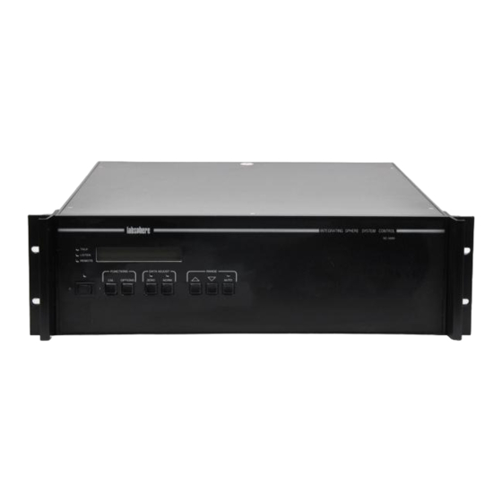
In the stand-alone mode of operation, SC-5500 control is obtained through the buttons on the front panel of the instrument. A list of SC-5500 control features is provided here for user refer- ence. The front panel of the SC-5500 is illustrated in Figure 1. - Page 17 R ESPO N SIV ITY Figure 7. Menu item sequence in the SC-5500 firmware. If your SC-5500 is part of an integrating sphere system with Labsphere software, the software application can access the non-communications parameters on the Options Menu. When the SC- 5500 powers up, the default parameters will always be restored.
- Page 18 The default setting at power up is ENABLED. IEEE Address You can program the SC-5500 for a different IEEE address if the default address is already taken by another piece of equipment. The possible addresses include any number between 1 and 15, inclusive.
-
Page 19: Calibration
The calibration coefficients embedded in the SC-5500 firmware is not valid for other systems or with different detectors. The radiometer also can be used, however, to display the detector voltage or detector current. Cali- bration coefficients for CAL0 and CAL1 are installed on all SC-5500 radiometers to display detector voltage and current respectively. - Page 20 The same responsivities and correction multipliers discussed above are embedded into the EPROM in your SC-5500 so the instrument can be operated remotely or in stand-alone mode. SX-01635-000, Rev. 5 Artisan Technology Group - Quality Instrumentation ... Guaranteed | (888) 88-SOURCE | www.artisantg.com...
-
Page 21: Sc-5500 Programming
SC-5500, you need an RS-232C cable with the null modem. SC-5500 Programming Commands Commands given to the SC-5500 must be sent in capital letters and each command has to be fol- lowed with an X. For instance, to activate the AUTORANGE function via the terminal program, the following command must be sent, A0X. - Page 22 Calibrations Typing C and the number that corresponds to a calibration stored in the SC-5500 sets the instrument for that specific calibration. (n) is the one or two digit decimal number of the calibration. Example: C0X sets the SC-5500 to Cal 0, C1X sets the SC-5500 to Cal 1.
-
Page 23: Ieee-488 Programming
Table 3. Programming commands for detector ranging. Remote Operation LØX Sets the SC-5500 in the remote control mode. In this mode the front panel controls of the instrument are deactivated. Turns the remote control mode off and reactivates the front panel controls. -
Page 24: Rs-232C Programming
SC-5500 to perform an instruction, an IBCMD (Interface Bus Command) state- ment can be sent out to set up the nature of the communication occurring (i.e. SC-5500 as a TALKER and the interface board as a LISTENER). Once the communication parameter has been established, string commands as described in Appendix C can be sent to instruct the SC- 5500 to perform the required actions. -
Page 25: Maintenance
DANGER: Incorrect fuse installation can cause a potential shock hazard or subject the SC-5500 instrument to electical damage. The voltage cartridge has been set at Labsphere prior to shipping and the correct power cord is provided at shipment to suit your power source. Should you ever need to change the configura- tion, make sure the desired setting of 115 or 230 VAC is prominently displayed in the window as shown in Figure 8. - Page 26 To change the input voltage configuration, proceed as follows: Remove the power cord and gently pry up the plastic tab on the top end of the mod- ule in Figure 8 using a slotted screwdriver. Fuse Holder Plastic T ab Figure 9.
- Page 27 Remove the voltage cartridge from the module and remove the defective fuses. At the fac- tory, Labsphere always installs two fuses of the same rating into the voltage cartridge, no matter what the intended voltage configuration. Install the appropriate replacement fuses into the cartridge, as shown in Figure 12, and load the cartridge into the input module in the correct orientation.
- Page 28 Labsphere Customer Service department at (603) 927-4266. The SC-5500 uses a 1 amp, 250 volt, slow-blow GDA-type fuse. Two 1A fuses are required if operating the SC-5500 at 230 VAC. If a second fuse blows, contact the Labsphere Customer Ser- vice Department at (603) 927-4266.
-
Page 29: Appendix A Specifications
Appendix A Specifications Radiometer Performance Current Input Characteristics at 25°C Range Resolution Accuracy (% reading + counts) Accuracy (% reading + counts) 24 hr period 1 yr period 1 nA 0.1 pA 0.05 + 2 0.1 + 5 10 nA 1 pA 0.05 + 1 0.1 + 2... - Page 30 General Specifications Temperature Coefficient ± (0.02% of reading + 0.5 counts) per °C Noise Referred to Input 100 nV RMS/(Hz) Input Bias Current 10 pA maximum Input Impedance 100 Meg Ohm in parallel with 100 pF Analog Input Single Channel Input Connector twist-lock-type triaxial Isolation...
-
Page 31: Appendix B Schematics
Appendix B Schematics SX-01635-000, Rev. 5 Artisan Technology Group - Quality Instrumentation ... Guaranteed | (888) 88-SOURCE | www.artisantg.com... - Page 32 Figure 7. Typical DB37 setup for the SC-5500. The active pinout depends on your sys- tem configuration. SX-01635-000, Rev. 5 Artisan Technology Group - Quality Instrumentation ... Guaranteed | (888) 88-SOURCE | www.artisantg.com...
- Page 33 M ultiplexer RS-232C RS-232C Detector V oltage Driver Gain Control Guard Reference Network V oltage Circuit Figure 8. Functional block diagram of the SC-5500 radiometer. SX-01635-000, Rev. 5 Artisan Technology Group - Quality Instrumentation ... Guaranteed | (888) 88-SOURCE | www.artisantg.com...
-
Page 34: Appendix C Sample Programming
Appendix C Sample Programming SC-5500 programming examples are provided here for controlling the system through IEEE-488 and RS-232C interfaces. The IEEE-488 examples use functions referenced from the National Instruments NI-488.2M GPIB reference. In each case, one source code example is in C++, the other using QuickBasic. - Page 35 Send(gpib_card,sc_5500_address,"A0X",3,0); void auto_off (void) SendIFC(gpib_card); Send(gpib_card,sc_5500_address,"A1X",3,0); void display_3_digits (void) SendIFC(gpib_card); Send(gpib_card,sc_5500_address,"H0X",3,0); void display_4_digits (void) SendIFC(gpib_card); Send(gpib_card,sc_5500_address,"H1X",3,0); void lock_front_panel (void) SendIFC(gpib_card); Send(gpib_card,sc_5500_address,"L0X",3,0); void unlock_front_panel (void) SendIFC(gpib_card); Send(gpib_card,sc_5500_address,"L1X",3,0); void filter_on (void) SendIFC(gpib_card); Send(gpib_card,sc_5500_address,"F0X",3,0); void filter_off (void) SendIFC(gpib_card); Send(gpib_card,sc_5500_address,"F1X",3,0); void go_to_range (int range) //range 0 is the most sensitive range (e-9) //range 6 is the least sensitive range (e-3) char tempstr[10],junk[10];...
- Page 36 //the Receive command will read up to 25 characteres until 0x0a (decimal 10) is //recieved. The SC-5500 sends back an 0x0d 0x0a after each reading. //Reading the data in this manner allows this function to work in both 3 1/2 and 4 1/2 digit mode Receive(gpib_card,sc_5500_address,buffer,25,10);...
- Page 37 Send(gpib_card,sc_5500_address,"P3J1J2J3J4J5J6J7J8X",19,0); Send(gpib_card,sc_5500_address,"P4J1J2J3J4J5J6J7J8X",19,0); void set_port (int port, int position) //This sequence sets up the SC-5500 control ports to control the VAC-1000. The second argument is the //attenuator position, 0 through 255, you want the attenuator to assume char bit_values[25],position_values[25],temptr[25],junk[25],attenuator_values[25]; int i,j;...
-
Page 38: Ieee-488 Programming In Quickbasic
SC-5500 does not recognize, an INVALID COMMAND ERROR status message will be dis- played on the front panel of the SC-5500. The duration of the display will be as long as required to clear the buffer of the characters. If there is a sufficient amount of unrecognizable characters in the buffer, it may become necessary to power off the SC-5500 and then power it back on. -
Page 39: Rs-232C Programming In C
‘NullEND = Terminator ‘The SC-5500 will execute the Receive command by placing one display value into its buffer. The buffer is then swept and ‘the data sitting there is placed into the string variable. This one command will perform both tasks. The O0X command is ‘only an RS-232 command. - Page 40 char CommString[32]; char PortString[32]; const int RecvQueueSize=2048; const int SendQueueSize=2048; strcpy(&CommString[0],"COM"); //COM itoa(comport,&PortString[0],10); strcat(&CommString[0],&PortString[0]); //COM1 //Open a hailing frequency idComDev = OpenComm(&CommString[0], RecvQueueSize, SendQueueSize); if(idComDev<0) { //ReadHand the OpenComm Failure err = CloseComm(idComDev); return -1; strcat(&CommString[0],":9600,n,8,1"); //Translates Device Definition String to DCB codes err = BuildCommDCB(&CommString[0], &dcb);...
- Page 41 void auto_on_serial(void) WriteComm(sc_idComDev,"A0X",strlen("A0X")); void auto_off_serial(void) WriteComm(sc_idComDev,"A1X",strlen("A1X")); void display_3digits_serial(void) WriteComm(sc_idComDev,"H0X",strlen("H0X")); void display_4digits_serial(void) WriteComm(sc_idComDev,"H1X",strlen("H1X")); void lock_panel_serial(void) WriteComm(sc_idComDev,"L0X",strlen("L0X")); void unlock_panel_serial(void) WriteComm(sc_idComDev,"L1X",strlen("L1X")); void filter_on_serial(void) WriteComm(sc_idComDev,"F0X",strlen("F0X")); void filter_off_serial(void) WriteComm(sc_idComDev,"F1X",strlen("F1X")); void goto_range_serial(int range) char tempstr[10],junk[10]; memset(tempstr,'\0',10); memset(junk,'\0',10); strcpy(tempstr,"R"); strcat(tempstr,itoa(range,junk,10)); strcat(tempstr,"X"); WriteComm(sc_idComDev,tempstr,strlen(tempstr)); void goto_cal_serial(int cal) SX-01635-000, Rev. 5 Artisan Technology Group - Quality Instrumentation ...
-
Page 42: Rs-232C Programming In Quickbasic
WriteComm(sc_idComDev,"O0X",3); //Ask the SC-5500 for a reading wait_n_mseconds(1000); //read the data back one character at a time until all characters have been read int BytesRead = 0; DWORD current_time; DWORD start_time = GetTickCount();... - Page 43 ‘bi-directional communications PRINT #1, "C1H1L1X" ‘Set SC-5500 for 4 1/2 Digits, to Cal 0 and to remote mode ‘operation SLEEP 1 ‘Pause for command to be processed by SC-5500 ‘AutoRange setup: PRINT #1, "A0X" ‘Turn on Autorange SLEEP 5 ‘Pause for command to be processed by SC-5500 PRINT #1, "A1X"...
Need help?
Do you have a question about the SC-5500 and is the answer not in the manual?
Questions and answers