Table of Contents
Advertisement
Quick Links
Advertisement
Table of Contents

Summary of Contents for Effort International TX3000
- Page 1 RF SYSTEM(RS009) Manual TX3000 TUNING GUIDE...
-
Page 2: Table Of Contents
1.2. Receiver Electronics ......................8 Chapter 2 RX3000 Filter Concept....................8 Chapter 3 TX3000Cable\Opto Synchronization Setting ..............9 3.1. TX3000 cable synchronization setting ................9 3.2. TX3000 Opto Synchronization Setting ................14 Chapter 4 Tuning.......................... 19 4.1. One (1) Opto TX Output ....................19 4.2. -
Page 3: Chapter 1 Introduction
5.2. Socket Specifications ....................... 22 Chapter 1 Introduction This manual describes the TX3000 as well as the setup and tuning procedures needed to put the TX3000 and RX3000 electronics into operation. For details on the receiver board, see the RX 3000 Tuning Guide. - Page 4 4 standard TX3000 (as synchronization slaves), clusters of up to 7 TX3000 may be synchronized. This way up to 7 checkout or 14 exit-gates (in a row) may be configured without need of a master rack.
-
Page 7: Digital Part
Jumper J4 is used to select the desired sweep frequency. If the board is equipped with two opto transmitters (bi-opto TX3000 board), the swept HF signal will be automatically output (see section 4). This allows the synchronization of two additional transmitters. -
Page 8: Receiver Electronics
False alarms due to conducted noise on the power lines can be avoided if the power lines are filtered every 4 to 6 meters. If TX3000’s are used, this is done automatically and the power line between the transmitters is not longer than 6 (8.2MHz) meters. If the length of the power cable between the transmitters is longer than 4 to 6 meters, additional filter boards have to be use. -
Page 9: Chapter 3 Tx3000Cable\Opto Synchronization Setting
Chapter 3 TX3000Cable\Opto Synchronization Setting 3.1. TX3000 cable synchronization setting On the TX3000 are two optional Wire Cable Sockets,one is Cable In and the other is Cable Out. 3.1.1. TX3000 cable synchronization output setting (master) • J15 must be 2-3 IN •... - Page 10 • must be connect by twisted-pair The system can provide two sets of cable in.On the board of TX3000,it is annotated as X3(Cab In), N0. 1 and 2 of X3 is the first group ,and N0. 3 and 4 is the second group.You only need one group in actual use.Each cable in should connect to the corresponding...
- Page 13 TX3000 board of level 1 (bi-opto version, configured as master) feeds the synchronization signal to the two TX3000 boards of level 2 (bi-opto version, configured as slave). The TX3000 board of level 2 can also feeds the synchronization signal of the level 1 to the TX3000 boards of level 3.
-
Page 14: Tx3000 Opto Synchronization Setting
3.2. TX3000 Opto Synchronization Setting On the TX3000 board are two Opto synchronization output sockets and one Opto synchronization input socket.Synchronization output sockets are TX1(Opto Out1) and TX2(Opto Out2);Synchronization input socket is RX1(Opto In). 3.2.1. TX3000 Opto Synchronization Output Setting (master ) •... - Page 17 The optically transmitted synchronization signal may be repeated only once, therefore no synchronization repeater should ever feed another repeater. A basic configuration following this rule is shown below. The TX3000 board of level 1 (bi-opto version, configured as master) feeds the synchronization signal to the two TX3000 boards of level 2 (bi-opto version, configured as slave).
- Page 18 3.3 TX3000 Opto/cab Cablig from Master Rack If a system consists of more than seven transmitters, a master rack has to be used as a synchronization source. A possible configuration using a master rack and TX3000 is shown below.
-
Page 19: Chapter 4 Tuning
4.2. Preparation • Power OFF the TX3000 board (remove PWR connector at socket X1). • Ensure that the antenna is connected to the correct socket (X5) on the TX3000 board. • Turn the amplitude potentiometer R76 (LVL to almost (7/8) full power clockwise). -
Page 20: Power On Adjustments
* Factory default setting 4.3. Power On Adjustments • Power ON the TX3000 board (insert PWR connector at socket X1). • Check the red Temp-Limit LED is ON: Operation OK. • If the LED is going OFF and ON: − reduce the emitted power with the amplitude potentiometer R76. -
Page 22: Chapter 5 Appendix
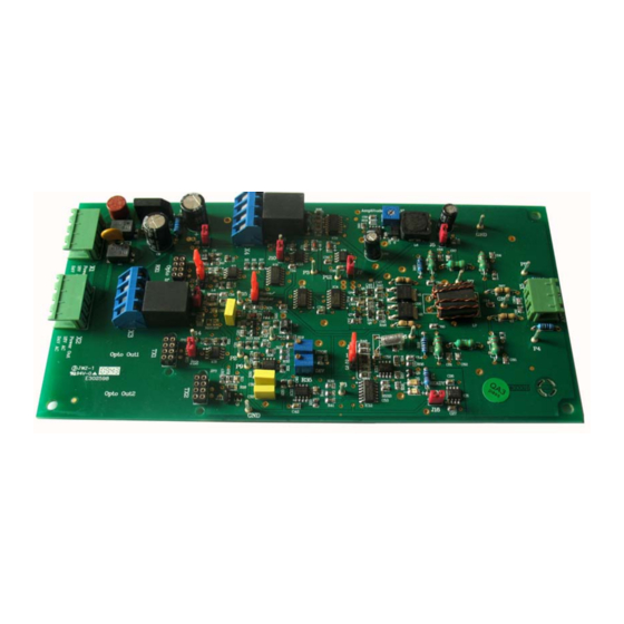
Chapter 5 Appendix 5.1. TX3000 Board NOTE: A. Cable output socket B. Optical cable input socket C. Power input socket D. Power output socket E. Cable input socket F. Optical cable output socket 1 G. Optical cable output socket 2 H. - Page 23 Cable socket have both a set of input socket and output socket, the socket of NO.1 and NO.2 are a pair of input (output), the socket of NO.3 and NO.4 are a pair of input (output). When you want to consist a complex system, using this socket not only can save the number of transmitters, but also play a role in synchronization.
Need help?
Do you have a question about the TX3000 and is the answer not in the manual?
Questions and answers