Advertisement
Quick Links
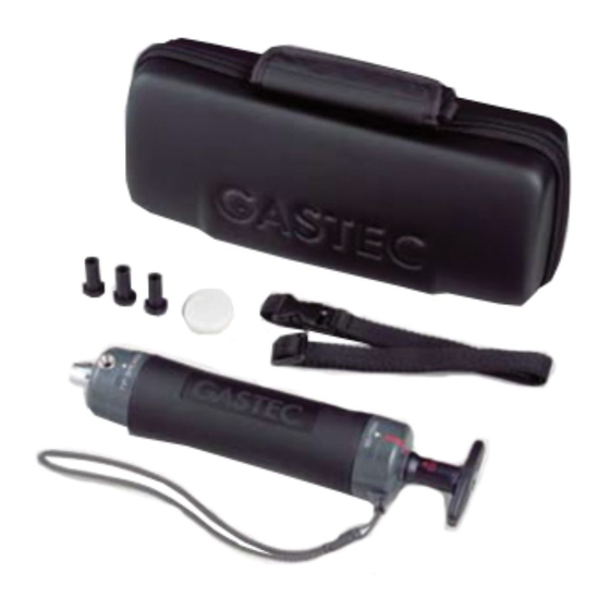
Gastec GV-100S and GV-110S Sampling Pump Manual
GV-100S Sampling Pump
GV-110S Sampling Pump With Counter
The Gastec precision pump (GV-100S) and Gastec Precision Pump with a counter (GV-100S) is
designed specifically to be used with Gastec standard and polytec tubes. Using this range you can
monitor up to 600 gases and vapours.
The Gastec precision pump and Gastec Precision Pump with a counter can precisely collect a
sample volume for a detector tube. The full-stroke (100ml) and the half stroke (50ml) positions are
marked exactly by the red line on the pump shaft, and the handle is precisely locked at those
positions. If you pump fully n times by allowing for sampling time intervals, a volume of 100ml x n
can be sampled. Each detector tube is calibrated based upon a prescribed (standard) volume of
sample. Also the pump piston has been designated with a smaller diameter so the handle can be
pulled out with even less effort. The Gastec precision pump design proves you with advanced and
non sparking design and superior features.
Advertisement

Summary of Contents for a1 cbiss Gastec GV-100S
- Page 1 Gastec GV-100S and GV-110S Sampling Pump Manual GV-100S Sampling Pump GV-110S Sampling Pump With Counter The Gastec precision pump (GV-100S) and Gastec Precision Pump with a counter (GV-100S) is designed specifically to be used with Gastec standard and polytec tubes. Using this range you can monitor up to 600 gases and vapours.
- Page 2 Operating Procedures for GV-100S and GV-110S Inspecting the air-tightness of the sampling pump NOTE: When there is a leak in the sampling pump, you cannot obtain the correct measurement values e.g. measured values may be lower than the actual values. Be sure to check the sampling pump for air- tightness before doing any measurements.
- Page 3 4) Securely hold the cylinder of the sampling pump. Then, pull out the handle fully along the red guide line on the pump shaft to the lock position, and wait 1 minute. At this time, make sure that the flow finish indicator is not white.
- Page 4 Sampling Using the Pump 1) Break off both ends (tips) of the detector tube by using the provided tube tip breaker or the tube tip holder (GAS721). In the case of a twin tube, break off both ends of both tubes and connect the ends of the tubes marked with a ©...
- Page 5 If you are using the GV-110S pump with a counter, please follow the instructions on page 9. 4) Direct the tube end to the point of measurement and pull out the handle fully (for 100ml sampling) or halfway (for 50ml sampling) along the guide line to the lock position. NOTE: If you are using the GV-110S pump with a counter, do not grasp the counter, otherwise the counter will not operate properly and may result in a malfunction.
- Page 6 6) Remove the detector tube from the pump. This completes the sampling process. NOTE: Remove broken glass tips in the pump head before it becomes full. Open the dust cap (on the opposite side of the tube tip breaker of the pump head block) and shake out the broken glass tips carefully and dispose safely of them.
- Page 7 NOTE: The counter will not increase if the handle mark is at ▲50 (50ml) The counter ring cannot be rotated while the handle is pulled out. Do not try to force it to rotate because you may break the counter. Do not grasp the counter when sampling.
- Page 8 When the demarcation of the colour change layer is pale. Read the value in the middle between the dark layer end and the pale layer end. In this exaggerated example, the reading should be 5, which is in the middle between 4 and 6. Correction for Temperatures If the tube reading requires temperature correction within the measurement temperature of 0ºC to 40ºC (32ºF to 104ºF), read the temperature of the sample point at the increment of 5ºC (9ºF).
- Page 9 Next, add the two true concentration values obtained from above and divide them by 2 (known as proportional allocation). The resulting value shown in the shading area in the table on the next page is 0.425%. This is the true concentration factor at 35ºC (95ºF) at a reading of 0.5% Correction for Humidity If the tube reading requires humidity correction with the measurement temperature of 0ºC to 40ºC (32ºF to 104ºF), read the ambient humidity at the sample point using the no.6 Gastec Water Vapour...
- Page 10 Correction for the number of pump strokes Make the following correction when measurements were made for a number of strokes other than the specified number. Some detector tubes can measure concentrations beyond the printed scale. The Gastec Technical Handbook (HBE) shows each available tube range of concentration for measurement (measuring range), the number of pump strokes (n) required and if applicable the stroke correction factors.
- Page 11 Correction for Atmospheric Pressure Tube readings are affected by significant fluctuations of atmospheric pressure. All Gastec detector tubes are calibrated based on a normal atmospheric pressure of 1013hPa (760mmHg) and their indications will not be affected over the range of ± 10% of normal pressure (912 to 1114hPa or 684 to 836mmHg).
- Page 12 If you are still experiencing problems please call a1-cbiss for more technical advice or replace your pump. Maintenance Procedures 1) Turn the back plate anti-clockwise to remove the piston from the cylinder. 2) Remove the old lubricant from inside the cylinder and around the perimeter of the piston with a soft cloth 3) Apply the lubricant evenly on the inside of the wall at the opening of the cylinder.
- Page 13 The parts listed below are important for proper air-tightness. Therefore, repairs and replacement parts should be repaired by a1-cbiss if required. Repair of the flow finish indicator A malfunctioning flow finish indicator may lead to air leaks in the sampling pump. If any abnormality is found, please contact us.
Need help?
Do you have a question about the Gastec GV-100S and is the answer not in the manual?
Questions and answers