
Summary of Contents for Exergy Solutions Bertie
- Page 1 Alberta E-Vent 1.0 “Bertie” Exergy Team Collaboration Emergency Resuscitator User Manual / Quick Start Guide Version 1.3 June 3, 2020...
- Page 3 • PLC Electronic Solutions • • Royal Circuits • Suncor Energy • TIPP Consulting • University of Calgary AERO-CORE and ATSSL • Volunteers We hope “Bertie” can help you save lives Alberta E-Vent User Manual Version 1.3 June 3, 2020...
-
Page 4: Important: Read Before Use
Manual; any error, failure or defect of such Device or the Manual; or, any harm, loss or injury caused Exergy Solutions Inc. (“Exergy”) makes no representations, by such Device or the Manual. warranties or covenants, whether statutory, express, implied, by course of communication or dealing, or otherwise with respect to the Manual and the Device. - Page 5 Issued for RT Testing 2020-05-01 Issued for Submission 2020-05-20 Issued for Resubmission 2020-06-03 Issued for Use EMERGENCY CONTACT INFORMATION If you require technical assistance, please contact Exergy Solutions: Email: covid_client_coordinator@exergysolutions.com Website: www.exergysolutions.com/covid-19/ Alberta E-Vent User Manual Version 1.3 June 3, 2020...
-
Page 6: Table Of Contents
Contents Collaboration ................i Important: Read before Use ............ii Chapter 1: For Your Safety and that of Your Patients ....1 1.1. Safety Information ............1 1.1.1. Definitions ............... 1 1.1.2. Warnings ................. 2 1.1.3. Caution ................3 Chapter 2: Intended Use ............4 2.1. - Page 7 Chapter 7: Displays and Settings ..........19 7.1. User Interface Displays ..........19 7.2. Remote Display .............20 Chapter 8: Alarms and Indicators ..........21 8.1. Status Indicators ............21 8.2. AC Power loss and Power off Alarm ......21 8.3. Alarm Silence..............21 8.4. Alarm Reset ..............21 8.5.
-
Page 8: Chapter 1: For Your Safety And That Of Your Patients
Chapter 1: For Your Safety and that of Your Patients The Alberta E-Vent is an electrically driven automated resuscitator based on the robotic operation of a Health Canada and ISO approved Bag Valve Mask Assembly (BVM, e.g. Ambu SPUR II). It is designed and built to rapidly support health agency ventilator shortages caused by the Covid-19 pandemic. -
Page 9: Warnings
1.1.2. Warnings ▪ WARNING! Do not touch electrical connectors of the Strictly follow these Instructions for Use. ventilator accessories, patient Any use of the product requires full understanding simultaneously. and strict observation of all portions of these ▪ Due to possible fire hazard, the ventilator instructions. -
Page 10: Caution
1.1.3. Caution CAUTION! The following cautions apply any time you work with the Alberta E-Vent. ▪ Ensure that the voltage selection and installed fuses or breakers are set to match the voltage and ampacity of the wall outlet, otherwise damage may result. ▪... -
Page 11: Chapter 2: Intended Use
BVMs are done so at the risk of the operator and Chapter 2: Intended Use patient. The Alberta E-Vent is an automated resuscitator 2.1. System Configuration intended for short-term respiratory support, monitoring and treatment of adult patients when a The Alberta E-Vent is composed of the Resuscitator conventional ventilator is unavailable. -
Page 12: Disclosures / Deficiencies
▪ Electronics are housed in an all metal enclosure to suppress Electrical Magnetic Interference (EMI) from surrounding devices environment. ▪ A membrane covers the user interface and control box to facilitate Alberta E-Vent surface cleaning, sterilization and prevent debris and other materials from penetrating into the enclosure ▪... -
Page 13: Chapter 3: Care
Chapter 3: Care 3.1. Cleaning ▪ All parts potentially contacting patients or clinicians must be sanitized, disinfected or sterilized according to standard hospital policy. ▪ The hospital supplied BVM and Ventilation Circuit is considered single use only and disposable. It must be replaced for each new patient. -
Page 14: Chapter 4: What's What
Chapter 4: What’s what 4.1. Alberta E-Vent Overview Figure 4-1 Complete Alberta E-Vent Figure 4-2 Resuscitator Mechanism with Splashguard Figure 4-1 above illustrates the complete Alberta E-Vent and is composed of three main assemblies: ▪ Resuscitator Mechanism (17) with Splashguard (23) ▪... -
Page 15: List Of Components
4.2. List of Components The Alberta E-Vent Resuscitator Mechanism and User Interface are pre-assembled and supplied with several Ventilation Circuit parts as indicated in Table 4-1 below. Table 4-1 Alberta E-Vent Components List Name Supplied BVM *2 Hospital Figure 4-3 Ventilation Circuit – Hospital Supplied Components Y adapter Exergy Pressure Relief Valve (PRV) -
Page 16: Hospital Supplied Accessories
4.3. Hospital Supplied Accessories 4.3.1. Uninterruptable Power Supply (UPS) The Alberta E-Vent will not function if a loss of power occurs, although it has been designed to alarm clinicians in the event that it is no longer receiving power. Hospitals have the option to add a UPS to the system in order to guarantee reliable power in the event of a blackout or if they need to transport the patient. -
Page 17: User Interface (Ui)
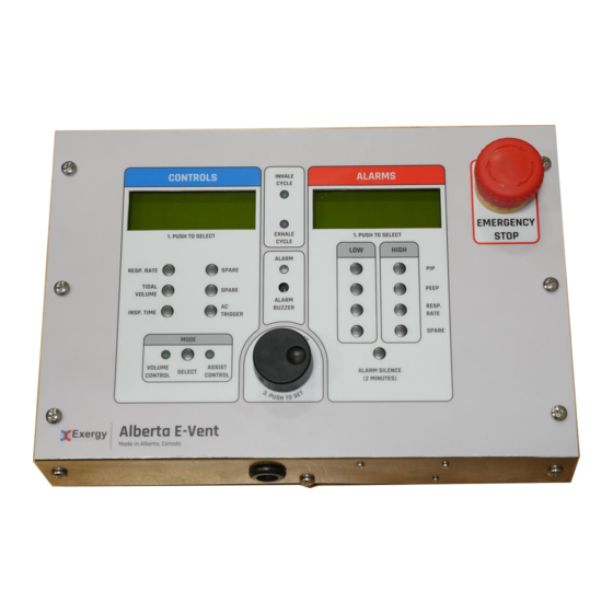
4.4. User Interface (UI) Figure 4-6 User Interface 1. Controls Display (LCD 1) is used to display 4. Spare buttons (total of 5). the Resp. Rate, Trigger Pressure, Tidal 5. Scroll Wheel is used to select different Volume, and Inspiration Time. Also displays operating and alarm parameters. - Page 18 7. Tidal Volume setting* (LCD 1) 22. Alarm Buzzer audibly notifies attendant there is an alarm condition. Specific alarm is Range: 40-100% identified on LCD 2 and the red remote 8. Inspiration Time setting* (LCD 1) display. Range: 0.5 to 3.0 seconds 9.
-
Page 19: Chapter 5: Preparation
Step 3 Chapter 5: Preparation 5.1. Assembling the PRV (Pressure Relief Valve) Step 1. Ensure you have these three items and lay them on a clear space. Step 4 Step 2. Unscrew the lid completely and remove from the valve. Note the small ring and large ring (indent side on spring side) positions. -
Page 20: Assembling The Patient Valve
5.2. Assembling the Patient Valve Step 1. The Patient Valve is assembled by pulling a valve out of one of the BVMs. Step 2. Clip the top of the port with scissors. This can be seen in the figure (orange circles). This enables the User Interface pressure sensing tubing to fit over the port and create a seal. -
Page 21: Assembling The Ventilation Circuit
5.3. Assembling the Ventilation Circuit Figure 5-4 Ventilation Circuit Components Step 1. Attach a complete new BVM (1) to the Step 9. Connect Patient Valve (8) to PEEP Valve (11) Y-adapter (2) Step 10. Attach Patient Valve (8) directly to the Test Step 2. -
Page 22: Connecting The Resuscitator Mechanism To The User Interface (Ui)
5.4. Connecting the Resuscitator Mechanism to the User Interface (UI) See figure below for the UI connections and Section 4.2. CAUTION for component ID numbers. The Alberta E-Vent weighs less than 20 lbs and has potential pinch points. Employ safe lifting Step 1. -
Page 23: Checking Readiness For Operation
5.5. Checking readiness for operation WARNING! The following sections will need to be completed All testing procedures must always be performed off patient. after: ▪ each Ventilation Circuit assembly ▪ each BVM replacement ▪ each care and reassembly procedure 5.5.1. Power On Test NOTE: If the arms are not touching the BVM, there is an Once the ventilator is turned on, the mechanical... -
Page 24: Alarm Tests
5.5.2. Alarm Tests Table 5-1 Alarm Testing Methods Alarm Test Expected Result Calibration Fail Power on and allow unit to calibrate Arms move away from BVM automatically Limit switch closes Arms move inward to contact BVM. AC Power Loss / Power on and allow unit to calibrate Device loses power. -
Page 25: Chapter 6: Operation
Chapter 6: Operation NOTE: Use a prepared, operable and disinfected 6.1. Alberta E-Vent Pre-Use Check device to complete Pre-Use Check. Chapter 3: Care The Pre-Use Check must be carried out before each use. Chapter 5: Preparation Any operation of the device requires thorough knowledge of the Instructions for Use. -
Page 26: Chapter 7: Displays And Settings
Chapter 7: Displays and Settings 7.1. User Interface Displays Figure 6-1 Alarms Display (LCD 2) Figure 6-2 Alarms Display Screen (Default) Figure 7-1 Controls Display (LCD 1) Figure 6-3 PIP High Limit Setting Screen (HPI) Figure 7-2 Calibration Screen Figure 6-4 PIP Low Limit Setting Screen (LPI) Figure 7-3 Assist Control mode Home Screen (Default) Figure 6-5 PEEP High Limit Setting Screen (HPE) -
Page 27: Remote Display
7.2. Remote Display In addition to the two LCD screens there is also a remote, position-able display. This is for caregivers to view information from a safe area outside of the quarantine room and minimize exposure. The display switches between Inspiration Pressure and End Expiratory Pressure unless there is an active alarm. -
Page 28: Chapter 8: Alarms And Indicators
8.5.1. Mechanical Failure Chapter 8: Alarms and Indicators Causes: Commanded motor position does not match 8.1. Status Indicators feedback; Mechanical disconnection Consequences: The Alberta E-Vent displays the following status Device re-calibrates/locks out, shuts down (requires indicators power down and power up); No ventilation ▪... -
Page 29: Low Peep
8.5.4. Low PEEP Consequences: Single occurrence is not overly concerning, but Causes: ▪ multiple occurrences can exacerbate patient Break at any connection of tubing/plumbing ▪ Patient attempting to take a breath that isn't asynchrony and cause pneumothorax over time recognized by device Responses/Actions: ▪... -
Page 30: Chapter 9: Troubleshooting
Chapter 9: Troubleshooting Table 9-19- Troubleshooting Methods Fault Potential Cause Potential Solution ▪ ▪ Device does not Cables between the user interface Ensure that the cables between the calibrate and mechanical assembly not mechanical assembly and user connected interface are securely connected. ▪... - Page 31 Fault Potential Cause Potential Solution ▪ ▪ Buttons on UI Button is broken Unplug device, plug back in ▪ ▪ are not User Interface Malfunction Switch device off, and back on ▪ ▪ responding Unit is off Ensure all connections are secure ▪...
-
Page 32: Appendix A: Contact Information
Appendix A: Contact Information To request technical assistance or report malfunctions regarding the Alberta Vent, contact Exergy Solutions at: Technical Support: Contact Name and COVID Client Coordinator Title: Company Name: Exergy Solutions Telephone: 403-700-9333 Email: covid_client_coordinator@exergysolutions.com Street: 100 4 Ave SW, Suite 600... -
Page 33: Appendix B: Resuscitator Specifications And Accuracies
Appendix B: Resuscitator Specifications and Accuracies The Alberta E-vent has only been tested with the Ambu® SPUR® II - Disposable Resuscitator (REF 520211000). The tidal volumes and FiO2 table are only valid for this particular brand of BVM. While other BVM’s can be used, the user must conduct their own tidal volume mapping and verify that the device performs as expected with respect to all user settable parameters. -
Page 34: Appendix C: Software Specifications
Appendix C: Software Specifications Alberta E-Vent User Manual Version 1.3 June 3, 2020... - Page 35 Alberta E-Vent User Manual Version 1.3 June 3, 2020...
-
Page 36: Appendix D: Technical Variances With Mit
Appendix D: Technical Variances with MIT Mechanical design alterations to the MIT design include: 1. The metal under the bag has been reshaped to increase rigidity to the Resuscitator Mechanism and reduce abrasion with the bag. 2. At both ends of the BVM, plastic clips have been added to allow elastic bands to go around the BVM and hold it in the ideal position. -
Page 37: Appendix E: Tidal Volume & Fio2 Titration Tables
Appendix E: Tidal Volume & FiO2 Titration Tables Look up table (Table E-1) to be used with the device in order to set tidal volumes. Table E-1 Tidal Volume Setting Table Tidal Volume Volume of air NOTE: Setting delivered Tidal Volume Setting table (Table E-1) is 174 ml only valid for Ambu-Bag Spur II REF 189 ml... - Page 38 Look up table (Table E-2) to be used with the device in order to set tidal volumes Table E-2 FiO2 Titration Look up Table Tidal Volume Setting 100% 100% 100% 100% 100% 100% 100% NOTE: FiO2 Titration Look up Table (Table E-2) is only valid for Ambu-Bag Spur II REF 520211000 with a RR of 16 bpm.
-
Page 39: Appendix F: Quick Start Guide
Step 3 Appendix F: Quick Start Guide Preparation Assembling the PRV (Pressure Relief Valve) Step 1. Ensure you have these three items and lay them on a clear space. Step 4 Step 2. Unscrew the lid completely and remove from the valve. Note the small ring and large ring (indent side on spring side) positions. - Page 40 Assembling the Patient Valve Step 3. The Patient Valve is assembled by pulling a valve out of one of the BVMs. Step 4. Clip the top of the port with scissors. This can be seen in the figure (orange circles). This enables the User Interface pressure sensing tubing to fit over the port and create a seal.
- Page 41 Assembling the Ventilation Circuit Figure F-4 Ventilation Circuit Components Step 1. Attach a complete new BVM (1) to the Step 9. Connect Patient Valve (8) to PEEP Valve (11) Y-adapter (2) Step 10. Attach Patient Valve (8) directly to the Test Step 2.
- Page 42 Connecting the Resuscitator Mechanism to the User Interface (UI) See figure below for the UI connections. CAUTION Step 1. Attach the Resuscitator Mechanism Motor The Alberta E-Vent weighs less than 20 lbs and has potential pinch points. Employ safe lifting Power Connector cable and Encoder/Limit procedures when handling.
- Page 43 Checking readiness for operation WARNING! All testing procedures must always be performed The following sections will need to be completed off patient. after: ▪ each Ventilation Circuit assembly ▪ each BVM replacement ▪ each care and reassembly procedure Power On Test NOTE: If the arms are not touching the BVM, there is an Once the ventilator is turned on, the mechanical...
- Page 44 Alarm Tests Table F-1 Alarm Testing Methods Alarm Test Expected Result Calibration Fail Power on and allow unit to calibrate Arms move away from BVM automatically Limit switch closes Arms move inward to contact BVM. AC Power Loss / Power on and allow unit to calibrate Device loses power.
- Page 45 Operation NOTE: Use a prepared, operable and disinfected Alberta E-Vent Pre-Use Check device to complete Pre-Use Check Chapter 3: Care The Pre-Use Check must be carried out before each use. Chapter 5: Preparation Any operation of the device requires thorough knowledge of the Instructions for Use.
- Page 46 Tidal Volume Setting Table Table F-2 Tidal Volume Setting Table Tidal Volume Volume of air NOTE: Setting delivered Tidal Volume Setting table (Table F-2) is 174 ml only valid for Ambu-Bag Spur II REF 520211000. 189 ml 204 ml 220 ml 236 ml NOTE: Table F-2 Tidal Volumes were...
- Page 47 FiO2 Titration Look up Table Table F-3 FiO2 Titration Look up Table Tidal Volume Setting 100% 100% 100% 100% 100% 100% 100% NOTE: FiO2 Titration Look up Table (Table F-3) is only valid for Ambu-Bag Spur II REF 520211000 with a RR of 16 bpm. Alberta E-Vent User Manual Version 1.3 June 3, 2020...
-
Page 48: Appendix G: Glossary And Abbreviations
Appendix G: Glossary and Abbreviations Table G-1 List of Abbreviations Abbreviation Definition Assist Control Beats Per Minute / Respiratory Rate Bag Valve Mask High PEEP Alarm High PIP Alarm High Respiratory Rate Alarm Inspiration Time Low PEEP Alarm Low PIP Alarm Mode Ventilation Mode PEEP... -
Page 49: Appendix H: List Of Figures & Tables
Appendix H: List of Figures & Tables Figure 4-1 Complete Alberta E-Vent ........................7 Figure 4-2 Resuscitator Mechanism with Splashguard ..................7 Figure 4-3 Ventilation Circuit – Hospital Supplied Components ................ 8 Figure 4-4 Ventilation Circuit - Exergy Supplied Components ................8 Figure 4-5 Exergy Supplied Components ...................... - Page 50 Figure F-5 UI Connections ..........................35 Figure F-6 Complete Alberta E-Vent ......................... 35 Figure F-7 Controls Display Settings (LCD 1)..................... 36 Figure F-8 Alarms Display Settings (LCD 2) ....................... 36 Table 0-1 Revision History ..........................iii Table 4-1 Alberta E-Vent Components List ......................8 Table 5-1 Alarm Testing Methods ........................
-
Page 51: Appendix I: Index
Appendix I: Index Mechanical Failure, 19, 21 Mode, 4, 11 AC Power Loss Power Off, 21, 37 Alarm Reset, 21 Note, 1, 8, 10, 11, 14, 16, 17, 18, 19, 32 Alarm Silence, 11, 21 Alarm Summary, 21 Alarms Display, 10, 19 Operation, 18 Assist Control, 11, 19 PEEP High Limit Setting, 11, 19... - Page 52 www.exergysolutions.com/covid-19...
Need help?
Do you have a question about the Bertie and is the answer not in the manual?
Questions and answers