Advertisement
Quick Links
General Description
The PCS-1 allows you to turn your PC on/off with your existing TV or universal infrared (IR) remote.
This is especially useful for home theater PC (HTPC) users.
No soldering required. Splicers are included for connecting PCS-1 to PC power supply (ATX).
Auto-detect feature makes electrical connections a snap.
Requirements
PC with an ATX power supply. Most PCs are ATX. The PCS-1 is not designed for notebook PCs.
The PCS-1 is designed to fit behind a 1/4” hole that the user must drill into their PC case.
Installation Steps
Caution! Before beginning the installation, unplug the AC power from your PC.
The following installation steps assume that the PCS-1 module will be installed onto the inside of the front cover plate of
the PC. However, you can install it on any side you see fit.
Typical installation:
1. Locate a spot on the front of your PC case where you will drill the hole for the IR receiver.
Note that this must be in a location that is unobstructed during normal PC operation.
2. Verify that your PC is disconnected from AC power.
3. Remove the cover of your PC so that you can access the motherboard and ATX power supply.
4. If possible, remove the front cover plate of the PC for drilling the hole.
5. It’s recommended that you drill successively larger holes. For example, start with a 1/8” drill bit, then finish
with 1/4”. This will make for a hole with a smooth edge.
6. Once the hole is drilled, remove the red backing of the tape on the PCS-1 module.
7. (See the diagram on the next page for alignment details.) On the inside of the front panel, place the IR receiver
behind hole you drilled, and carefully press the PCS-1 module against the inside face so that the tape sticks.
8. Disconnect the PC power button cable from the motherboard and connect it to the 2-pin connector located
near the end of the twisted-wire pair of the PCS-1. The polarity does not matter, as the PCS-1 will auto-
detect. Plug the end of the twisted-wire pair from the PCS-1 module onto the 2-pin power switch connector
on the motherboard. Again, polarity doesn’t matter.
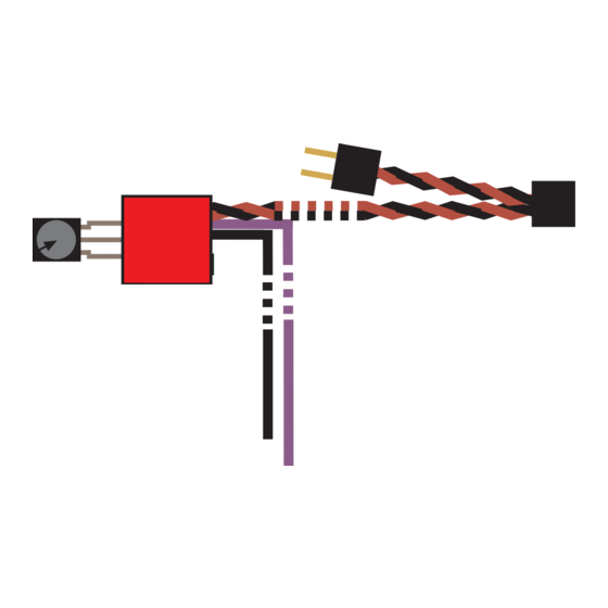
9. Refer to the diagram on the next page to connect the black and purple power wires.
Be very careful to connect the power wires to the correct colors. Not doing so will damage the
module and possibly your PC power supply.
Copyright SIMEREC
Universal Infrared Remote PC Power Switch
PCS-1
Advertisement

Related Manuals for SIMEREC PCS-1

Summary of Contents for SIMEREC PCS-1
- Page 1 Caution! Before beginning the installation, unplug the AC power from your PC. The following installation steps assume that the PCS-1 module will be installed onto the inside of the front cover plate of the PC. However, you can install it on any side you see fit.
- Page 2 ATX power supply. Caution: Be very careful to connect the wires correctly to the power supply. Failure to do so will damage the PCS-1 module and possibly your PC. PCS-1 Front View Place this behind the hole drilled into PC case.
- Page 3 This verifies that installation and programming are correct. If the LED of your PCS-1 blinks each time you press the programmed IR remote button, but the PC does not power on/off, then it is most likely that your motherboard requires a “hi” pulse instead of the “low“...
- Page 4 How to Properly Splice the Power Wires Both power wires from the PCS-1 module are painted green on the ends to aid in splicing as show below. The following example is for the black power wire. The procedure is the same for the purple power wire.
- Page 5 Below are the incorrect and correct alignments. (Note: For purposes of clearer illustration, that the wires are not shown in the splicer below.) INCORRECT ALIGNMENT This can result in the wire from the PCS-1 module not being properly captured. The pliers should be set to...
- Page 6 Note that the actual splice can be anywhere on the wire. ATX 20-pin Location of standby power wire for a 24-pin ATX connector. This view is of the connector as you look down onto the motherboard. ATX 24-pin Copyright SIMEREC...
Need help?
Do you have a question about the PCS-1 and is the answer not in the manual?
Questions and answers