Hussmann HGL-1BS Installation And Service Instructions Manual
Bottom & top mount remotes
Hide thumbs
Also See for HGL-1BS:
- Brochure (6 pages) ,
- Installation and service instructions manual (26 pages)
Table of Contents
Advertisement
January 2006
INSTALLATION & SERVICE
INSTRUCTIONS
FOR
HGL-1, 2 & 3 BOTTOM & TOP MOUNT
REMOTES
First Call for help (US and Canada):
1-800-922-1919
Soporte Tècnico y Asistencia (Mèxico):
01-800-522-1900
For a Service Network Locator and other
Information visit us at
www.hussmann.com
select Worldwide Locations
P/N OII – HGL Remotes
January 2006
HUSSMANN - GLOVERSVILLE
Advertisement
Table of Contents

Related Manuals for Hussmann HGL-1BS


Summary of Contents for Hussmann HGL-1BS
- Page 1 REMOTES First Call for help (US and Canada): 1-800-922-1919 Soporte Tècnico y Asistencia (Mèxico): 01-800-522-1900 For a Service Network Locator and other Information visit us at www.hussmann.com select Worldwide Locations P/N OII – HGL Remotes January 2006 HUSSMANN - GLOVERSVILLE...
-
Page 2: Table Of Contents
Introduction Inspection Location Skid Leg Installation (Top Mounts only) Leveling and Sealing (Bottom Mounts only) Top Decorative Panel Removal Shelves Air Distribution and Rear Flue Spacer Electrical Connections Serial Plate Information Start-Up Procedure General Up-Keep, Care & Cleaning, Routine Maintenance Operation and Maintenance Power Switches Temperature Control... - Page 3 TABLE OF CONTENTS CON’T Electrical Box Electrical Line Set Refrigeration Line Sets Pumpdown System on the Remote Unit Setting up the Pumpdown System Trouble Shooting Charts Electrical Components List Warranty and Parts Information Ordering Replacement Parts Warranty Parts Procedure Compressor Replacement Procedure Page 16-19...
- Page 4 INSTALLATION CHECK LIST HGL / HGM / HGS UPRIGHT CABINETS Level cabinet front to back and left to right. Level doors and ad- just torque as needed. On HGL cabinets, it is important this be done to ensure proper operation of evaporator fan switches. Is proper voltage supplied to cabinet? Cut and remove compressor shipping band (HGL only) Is timer set for correct time of day? Fail-safe at 40 minutes, de-...
-
Page 5: Introduction
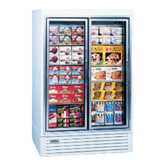
INTRODUCTION – Hussmann HGL B/T models are remote, low temperature, vertical display merchandisers for ice cream and frozen foods. Design features include heated glass doors for fog free visibility, auto- matic defrost, and efficient foamed in place non-CFC insulation. These models... -
Page 6: Leveling And Sealing (Bottom Mounts Only)
LEVELING – SEALING – Bottom Mounts Only The case can be leveled by shimming un- der the cabinet base frame, or by install- ing optional levelers. The self-closing doors require the cabinet to be properly leveled. End to end leveling will make the doors close with uniform speed and tightness. -
Page 7: Serial Plate Information
NOTE: Connecting this unit to any elec- trical supply other than specified on the serial plate will VOID the warranty and may result in serious damage to the unit. The cabinet should be supplied with its own service. SERIAL PLATE INFORMATION – The serial plate is located in the upper left hand corner of the case inte- rior. -
Page 8: Operation And Maintenance
GENERAL UP-KEEP, CARE and CLEANING, ROUTINE CARE and CLEANING – To insure good sanitation, appear- ance, and minimum maintenance, the cabi- net should be cleaned and washed regu- larly as use demands. Clean with mild de- tergent and warm water. DO NOT USE AN ABRASIVE CLEANER OR STEEL WOOL AS THEY WILL MAR THE FIN- ISH. -
Page 9: Thermometer
THERMOMETER – The thermometer is located by looking through the right hand door onto the right hand end of the fan plenum. The thermometer will also warm up rather rapidly when the case door is held open for a time such as when the case is being restocked or a shopper is making a decision on a product. -
Page 10: Defrost Time Clock
THE CABINET SUPPLY BREAKERS SHOULD BE DISCONNECTED BE- FORE REMOVING THE ENCLOSURE COVER. DEFROST TIME CLOCK – The timer is factory pre-set for two defrost cycles per day at 6:00 a.m. and 10:00 p.m. with a 40 minute failsafe. The timer must be adjusted to the proper time of day when the cabinet is started. -
Page 11: Lighting Door Switches
LIGHTING – Interior lighting is provided by electronically powered T-8 lamps located inside each doorway. The tubes are en- closed in a patented lens system to main- tain proper heat around the bulb for maximum, light intensity and to protect the product in case of breakage. -
Page 12: Refrigeration, Leak Testing, And Evacuation
other securely taped to one of the return bends two thirds of the way through the evaporator circuit. Some “hunting” of the expansion valve is normal. The valve should be adjusted so that during the hunting the greatest difference between the two probes is 3º... -
Page 13: Remote Condensing Unit And Compressor
√ Discharge the refrigerant-nitrogen mixture, allowing it to blow from the system as rapidly as possible, into an empty cylinder. Be sure that all ser- vice valves and solenoid valves are open to allow all of the mixture to be discharged. -
Page 14: Electrical Box
compressor will start properly. On start- up, the valve will hold the suction pres- sure at the desired setting until the suc- tion pressure has dropped below the set- ting, then the valve will open. If it becomes necessary to check or reset the valve, the case must be warm such as after a defrost cycle or from an initial warm case condition. -
Page 15: Trouble Shooting Charts
TROUBLE SHOOTING, LIGHTING TROUBLE SHOOTING WARRANTY and ELECTRONIC LIGHTING TROUBLE SHOOTING CHARTS TROUBLE Compressor runs continu- ously, Product too warm High head pressure Warm storage temperatures 1. Temperature control not SYSTEM INSTRUCTIONS PROBABLE CAUSE 1. Short of refrigerant 2. Inefficient compressor 3. - Page 16 Compressor runs continu- ously. Product too cold Compressor will not start, no noise 3. Cabinet location too warm 4. Too much refrigerant 5. Low voltage. Compres- sor cycling on overload 6. Condenser dirty 7. Dual pressure control not properly 1. Defective control 2.
- Page 17 TROUBLE SHOOTING CON’T Compressor will not start, cuts out on overload Icing condition in drain pan 1. Low voltage Lights won’t start 1. Low voltage 2. Defective compressor 3. Defective relay 4. Restriction or moisture 5. Inadequate air over con- denser 6.
-
Page 18: Electrical Components List
Lights flicker 1. Allow lamps to warm up 2. Check lamp sleeve for cracks 3. Check sockets for moisture and proper contact 4. Bulb replacement may be necessary 5. Check voltage 6. New bulbs tend to flicker until used Ballast hums 1. -
Page 19: Ordering Replacement Parts
Quality Con- trol Department. Contact your Hussmann Distributor for instructions on returning in-warranty parts. Warranty parts must be returned to the factory within 30 days of date of failure to assure proper disposition. -
Page 20: Compressor Replacement Procedure
Compressor Replacement Procedure – Replacement compressors will not be shipped from the Hussmann factory. They may be obtained from your nearest Copeland Wholesaler. Your wholesaler will replace, free of charge, any compressor found to be defective within twelve months of installation, not to exceed twenty months from the date of manufacture, as determined by the compressor serial number on the compressor serial plate. - Page 26 DOOR & FRAME HEATERS GREY FRAME HEATERS ALARM STAT DEFROST HTRS DRAIN DRAIN PAN HTRS TUBE HTRS SENSING BULB DEFROST CLOCK SENSOR JUMPER COMM 240 AC 120 NC C NO FAN SWITCH DOOR HEATERS DEFROST THERMOSTAT LIGHT SWITCH BALLAST ANTHONY FRAME NOTE: WIRES NOTED WITH WIRE HARNESS UP BACK OF CASE...
- Page 27 DOOR & FRAME HEATERS FRAME HEATERS ALARM STAT DEFROST HTRS DRAIN TUBE DRAIN PAN HTRS HTRS SENSING BULB DEFROST CLOCK SENSOR JUMPER COMM 240 AC 120 NC C NO LIGHT SWITCH FAN SWITCHES DOOR HEATERS DEFROST THERMOSTAT EVAP FANS REV EO # REV DATE REV BY APPROVED BY ELIMINATED OPTIONAL CONDENSATE PAN HEATER BALLAST...
- Page 28 DOOR & FRAME HEATERS FRAME HEATERS ALARM STAT DEFROST HTRS DRAIN PAN HTRS SENSING BULB DEFROST CLOCK SENSOR JUMPER COMM 240 AC 120 NC C NO FAN SWITCHES DOOR HEATERS DRAIN TUBE HTRS LIGHT SWITCH BALLAST ANTHONY FRAME DEFROST THERMOSTAT NOTE: EVAP FANS WIRES NOTED WITH...
Need help?
Do you have a question about the HGL-1BS and is the answer not in the manual?
Questions and answers