
Summary of Contents for AcrEase MR44BE
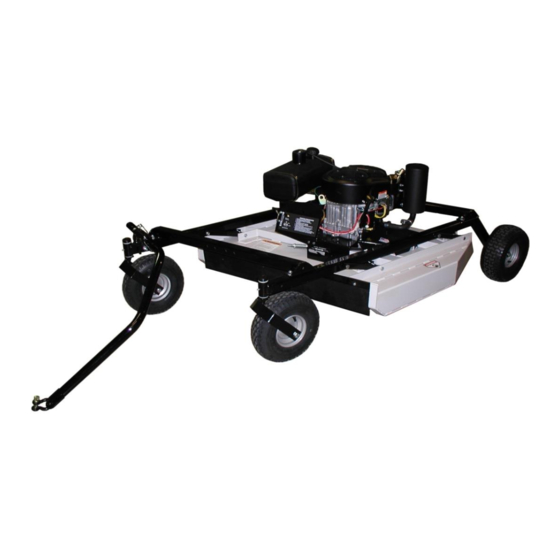
- Page 1 44” ROUGH CUT WITH ELECTRIC CLUTCH BLADE ENGAGEMENT OWNER’S MANUAL With Assembly Instructions For Models: MR44BE KUNZ ENGINEERING, INC. / MENDOTA, IL 61342 / PH (815) 539-6954 12/20...
-
Page 3: Table Of Contents
TABLE OF CONTENTS SAFETY INTRODUCTION…………………………………………………………………………….… 2 Safety Alert Symbol ……………………………………………………………………………….…... 2 Safety Information …………………………………………………………………………………..…. 3 Safety Signs and Locations ……………………………………………………………………….….. 4 ASSEMBLY INSTRUCTIONS ………………………………………………………………………..5 Items Included ……………………………………………………………………………………….… 5 Assembly of Rear Wheels and Carrier Arms ……………………………………………………….. 5 Installation of Cross Brace Tubes and Height Adjust Assy.…………………………………….…. 6 Installation of Tongue Assembly ………………………………………………………………….….. -
Page 4: Safety Introduction
SAFETY INTRODUCTION READ AND UNDERSTAND OWNER’S MANUAL BEFORE USING THIS MACHINE. All operators of this equipment must read and completely understand all safety information, operating instructions and maintenance. Failure to properly operate and maintain this mower could result in serious injury or death to the operator or bystanders. Your safety, and the safety of others, is very important. -
Page 5: Safety Information
IMPORTANT SAFETY INFORMATION Do not allow anyone to operate this equipment who has not fully read and comprehended the safety manual and who has not been properly trained in the safe operation of the equipment. Operator should be familiar with all functions of the unit. Keep hands, feet, hair and clothing away from moving parts. -
Page 6: Safety Signs And Locations
SAFETY SIGNS AND LOCATIONS 275003 – Danger 275007 – Warning Decal, Cut Hand & Foot Decal, Belt Sheild 275002 – Warning Decal, General Serial # and Model # Decal Clean or Replace Any Safety Signs That Are not Readable or Damaged Replacement decals can be purchased from your local dealer or Kunz Engineering Inc. -
Page 7: Assembly Instructions
ASSEMBLY INSTRUCTIONS Read the complete assembly instructions before starting the assembly. You should have: - one mower deck assembly - two carrier arm assemblies - two rear tire assemblies - one front cross brace tube and one rear cross brace tube with height adjust assy. - one ATV tongue assembly A. -
Page 8: Installation Of Cross Brace Tubes And Height Adjust Assy
3. Install the two carrier arm assemblies in the pivot arms, which are located on the mower deck assembly. Place the assembly so that the castered tires are on the front and the fixed tires are on the back. See figure 2. Secure with 1/2" x 3-1/2" hex head bolts and lock nuts provided on the pivot arms. - Page 9 1/2” x 3” Bolt Cross Brace Height Adjust Assy. Tube Figure 3: Cross Brace Tube Installation Screw Mounting Flat Height Adjust 1/2” x 1” Bolt Assy. Lower Deck Screw Mount Figure 4: Height Adjust Assy. Installation 4. Turn the crank on the height adjust assy. and raise the mower to its highest position. At this time securely tighten the 1/2”...
-
Page 10: Installation Of Tongue Assembly
C. INSTALLATION OF TONGUE ASSEMBLY 1. The tongue can be installed either on the left or right carrier arm assembly depending on how the tow-behind mower will be towed. See figure 5. Secure the hitch pivot on the chosen carrier arm assembly with the 1/2” x 3-1/2” hex head bolt, lock washer, and nut provided. 2. -
Page 11: Operation And Adjustments
Direction of Travel Screw Pin Shackle Clevis Shift Tongue Left or Right Between Holes Tongue 5/16” Wire Lock Pins Wire Lock Section of Wire Lock Pin (Placed Back From Direction of Travel) Figure 6: ATV Tongue Assembly OPERATIONS AND ADJUSTMENTS This safety alert symbol is used to indicate safety instructions. -
Page 12: Adjusting Cutting Height
Note: When pulling the mower directly behind, the hitch pivot should be fastened on the right carrier arm for maximum maneuverability. See Figure 5. When pulling the mower in the offset position the hitch pivot can be fastened on either the right or left carrier arm. See Figure 5. - Page 13 Adjust the mower as follows: 1. Pull the mower on to a smooth, level surface. 2. The desired cutting height can be determined by measuring the distance from the ground to the outside lower edge of the mower deck and adding 1-5/16”. The mower blade cutting edge is 1-5/16”...
-
Page 14: Starting Engine
Adjustment Crank Adjustment Nut Tube Height Adjust Support Figure 9: Securing Crank While Not In Use C. STARTING ENGINE Set parking brake on tow vehicle. Attach mower tongue to tow vehicle. Do not start rough cut mower unless it is attached to the tow vehicle. Turn on the fuel shut off valve (red colored rotating knob) located inline on the fuel hose. -
Page 15: Shutting Off Mower
D. SHUTTING OFF ROUGH CUT MOWER Shift to neutral and set the parking brake before dismounting the tow vehicle. Slow the engine speed down and disengage the clutch by pushing inward on the PTO switch. Allow engine to cool down for a short time before moving the ignition switch to the off position. Turn off the fuel shut off valve (red colored rotating knob) located inline on the fuel hose. -
Page 16: Maintenance
Stop the mower blades on the mower if the tow vehicle becomes stuck or stops going forward because of loss of traction. Shut off the engine on the mower before attempting to push or pull the tow vehicle. Inspect the ATV Tongue Assembly and tow vehicle hitch before each use. If any parts of the tongue or hitch look damaged or severely worn, discontinue use of the mower until the damaged or worn parts are replaced. -
Page 17: Mower Blade Removal, Balancing & Installation
Install the new belt and then adjust the tension as follows: See Figure 10. Only Include Spring in Measurement Front Engine/Clutch Initial Spring Length (New Belt): 2-1/2” to 2-9/16” Running Spring Length: 2-3/4” to 3-1/4” Figure 10: Belt Pattern, Spring Adjustment, and Brake Adjustment Adjust the nuts on the spring-loaded idler adjuster bolt until the length of the spring is between 2- 1/2”... -
Page 18: Lubrication
The Model MR44BE uses the Kunz Engineering Part # (202141) blade bolt. This particular hex head bolt is a 3/4” – 16NF x 1-1/4” long, grade 5 and its proper torque is 300 ft-lbs. -
Page 19: Specifications
ACREASE ROUGH CUT MOWER SPECIFICATIONS Model MR44BE ENGINE: Engine Make Briggs & Stratton Engine Model Commercial Turf Cylinders Cycles Crankshaft Vertical Engine HP Bore 3.12" Stroke 2.89" Displacement 44.2 cubic inches Oil Capacity 2 U.S. qt Crankshaft Dia. 1.0" Key Slot 1/4"... -
Page 20: Service Parts
ACREASE ROUGH CUT MOWER PARTS LIST Item Part # Description Quantity 202141 Blade Bolt, .75"-16UNF x 1.25" 214030 Cup Washer 216002 Wire Lock Pin, .31" x 2.50" 216009 Screw Pin Shackle Clevis 222005 Worm Drive Hose Clamp (7-7/8" to 9-1/8" Clamping Dia.) 222012 Single Split Collar (1"... - Page 21 Item Part # Description Quantity 600253 Safety Belting 600254 Battery Box Spacer 600264 Belt Sheild, Left 600265 Belt Sheild, Right 600268 Height Adjust Support 600291 Canister Support (California Only) 600305 Control Panel 600306 Tank Support 600314 Spring Support Bracket 600315 Tube Spacer (1.32"...
-
Page 22: Parts Drawing
ACREASE 44” ROUGH CUT MOWER PARTS... -
Page 23: Optional Equipment
OPTIONAL EQUIPMENT OPTIONAL WETLANDS KIT The optional wetlands kit features an extra set of tires for added ground support in soft or water saturated areas. The following are applications and features that the wetlands kit works best in. • Great for wetlands or marshy areas that stay wet all year around. •... -
Page 24: Electric Lift Kit
OPTIONAL EQUIPMENT OPTIONAL ELECTRIC LIFT KIT The optional electric lift kit consists of all of the mounting hardware, brackets, electric actuator and wiring with remote control panel. • Great for constantly changing terrain and grass/brush heights. • Allows for quick cutting height changes on the go from the seat of the tow vehicle. •... -
Page 25: Floatation Kit
OPTIONAL EQUIPMENT OPTIONAL FLOATATION KIT The optional floatation kit consists of one additional front and rear tire, mounting brackets and hardware. • Great for mowing around ponds and on rough uneven ground where scalping would normally occur. • Clamping style receiver allows for adjustments from side to side with both the front and rear tires. -
Page 26: Warranty Statement
The customer is responsible for transportation of the mower to and from the dealer. All AcrEase mowers at the time of sale have been designed and equipped to conform to the U.S. EPA Evaporative Standards. Kunz Engineering, Inc. warrants to the owner that all emission reducing evaporative components are free from defects in workmanship and material for the length of 2 years.
Need help?
Do you have a question about the MR44BE and is the answer not in the manual?
Questions and answers