Table of Contents
Advertisement
Advertisement
Table of Contents

Summary of Contents for mergedK tima 2P
- Page 1 tīma 2P/2R GPS Master Clocks Reference Manual tima-reference-en v3.14...
- Page 2 Copyright Notice All information provided in this document is the property of mergedK. mergedK grants its customers or potential customers the right to download, copy, store and print this document for the sole purpose of assisting them in the correct application of the products mentioned in this document.
-
Page 3: Table Of Contents
Contents 1 Introduction Product Description ......Key Features ......Firmware Versions . - Page 4 5 Settings General Settings ......21 GPS Receiver ......21 Time Zone .
-
Page 5: Introduction
Information in this manual applies to firmware revisions 0125-xxx and later. The firmware revision is displayed on the unit’s dot matrix display for a couple of seconds immediately after power up. The newest firmware versions and up-to-date versions of this document can be downloaded from https://mergedk.download. -
Page 6: Applicable Models
Check the contents against the packing list. If any of the contents listed are missing, please contact mergedK immediately (see contact information at the rear cover of this document). -
Page 7: Attention, Caution, Danger
Shall additional information be needed, please contact mergedK at any of the addresses provided on the rear cover of this document. Do not open or disassemble the product unless instructed to do so by mergedK. → ATTENTION The warranty will be void if the product is disassembled or otherwise handled inappropriately. - Page 8 tīma 2P/2R GPS Master Clocks Reference Manual...
-
Page 9: Installation
The label on the top cover of the equipment always reflects the particular con- figuration of the unit and can be used to determine the correct allocation of all connectors and signals, see figure for an example. mergedK GmbH • Reuchlinstr. 10-11 • 10553 Berlin • Germany • www.mergedk.com POWER SUPPLY ALARM SERIAL... -
Page 10: Power Connections
2.2.1 Clearances Allow adequate clearance for all connections on the rear panel. Make sure that the clearances provided for the antenna cable respect the specified minimum bending radius. Minimum bending radius depends on the cable used, see section (page 35) for applicable values. If the minimum bending radius of the antenna cable is not respected its impedance →... -
Page 11: Antenna Installation
2.4 Antenna Installation tīma master clocks require an active antenna in order to track GPS satellites. mergedK recommends using the antenna provided with the unit (SKU 90 02 01 5), but any other active antenna that can be powered from 3.3 Vdc (100 mA max- imum) can be used. -
Page 12: Decommissioning And Disposal
The antenna cable should be routed through a conduit, shielded from rain → ATTENTION and/or solar radiation. The conduit should not be shared with any power ca- bling. Total cable attenuation should be less than 45 dB. If using mergedK supplied cables, following maximum lengths can be achieved: External Maximum Cable... - Page 13 Nevertheless, dispose of the equipment in a safe, responsible and environ- mentally friendly manner, observing all applicable country-specific regula- tions. Avoid incineration or disposal to water courses at all costs. Installation...
- Page 14 tīma 2P/2R GPS Master Clocks Reference Manual...
-
Page 15: Operation
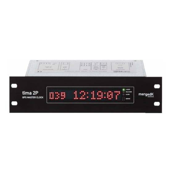
3 Operation 3.1 Front Panel Indicators The unit’s front panel comprises a dot matrix display and three LED indicators. 3.1.1 Dot Matrix Display The dot matrix display will show different information, depending on the equip- ment state. Startup: Immediately after power-up, the display shows the firmware version: LOCKED tīma 2P HOLD OVER... -
Page 16: Power Up Sequence
LOCKED tīma 2P HOLD OVER ALARM GPS MASTER CLOCK SERVICE Normal operation: During normal operation the display will show date, time and/or time zone information. Several formats are available, see section on page for de- tails. LOCKED tīma 2P HOLD OVER ALARM GPS MASTER CLOCK SERVICE... - Page 17 STATE INDICATORS DISPLAY OUTPUTS ALARM CONTACT POWER none on (closed) SELF Alarm blinks once none firmware version on (closed) TEST Holdover on progress bar STARTUP none followed by on (closed) IP address number of satellites none NOTIME Locked blinks on (closed) being tracked number of satellites none...
-
Page 18: Equipment States
Once all needed information is obtained and the internal oscillator is adjusted in phase and frequency, the equipment will enter the Locked state. Only now will the unit start displaying the local time on the dot matrix display and dis- tributing time over the outputs, as configured. -
Page 19: Web Interface
The equipment will raise a level 2 error and stop generating time signals. The dot matrix display will show a corresponding message. The default value for this threshold is 1 s. See section on page for infor- mation about how to change this to a different value. Normal operation, with time signal generation and display, is resumed as soon as enough satellites are re-acquired and the error estimate drops below the user-defined threshold. - Page 20 tīma 2P/2R GPS Master Clocks Reference Manual...
-
Page 21: Configuration And Equipment Log
4 Configuration and Equipment Log This chapters describes the configuration and log files of tīma master clocks and ways to access them. See chapter on page for a description of the settings and how they affect the behavior of the master clock. 4.1 The Configuration File tīma’s configuration file is a single text file (or ASCII file), segmented into Sec- tions. -
Page 22: The Log Files
Variable names are case insensitive. The value is any character on the right side of the equal sign. Quotes can be used to enclose the values, but they are not required. If no quotes are present, the value is understood as containing all characters between the first and the last non-blank characters before the comment. -
Page 23: Winscp
SFTP can be used. 4.4 WinSCP WinSCP can be downloaded from https://downloads.mergedk.com or from the WinSCP developer’s website (http://winscp.net). You can download an installation package or, instead, use the “portable” exe- cutable. -
Page 24: Other Sftp Clients
Figure 4.2: WinSCP warning window You can click and drag from either window to copy files between your computer and the equipment. You can also use the built-in editor to edit the configuration file on-line. Changes in the configuration file become active as soon as the file is saved or closed. 4.5 Other SFTP Clients On Mac OS X, use Cyberduck or ForkLift... -
Page 25: Settings
5 Settings This chapter describes the master clock’s settings. See chapter on page for the syntax of the configuration file and instructions on how to access it. 5.1 General Settings The parameters in this section allow the definition of identifier, location and contact strings for the unit. -
Page 26: Time Zone
5.3 Time Zone The parameters in this section allow the equipment to derive local time from UTC. If a daylight saving time (DST) rule is specified, summertime changes will be performed automatically. [TIMEZONE] Time zone parameters are defined in section [TIMEZONE]. OFFSET OFFSET is the time value that has to be added to the local time to get UTC during standard (not daylight saving) time. -
Page 27: Serial Time Strings
notation in the form where is the network prefix (the number A.B.C.D/n of significant bits used to identify a network). Only /8, /16, /24 or /32 are recognized as network prefix. For example, restricts accesss to hosts in the RESTRICT = 192.168.0.0/24 range 192.168.0.0 to 192.168.0.255. -
Page 28: Output Signals
time 12:34:56 12:34:57 12:34:58 12:34:59 UTC second rollover time reported in time string 12:34:56 12:34:57 12:34:58 12:34:59 Figure 5.1: Reported time with option PPS = CURRENT time 12:34:56 12:34:57 12:34:58 12:34:59 UTC second rollover time reported in time string 12:34:57 12:34:58 12:34:59 12:35:00... -
Page 29: Display Settings
the pulse marks the second rollover. SIGNAL = PPM A pulse with 200 ms width is generated once per minute. The rising edge of the pulse marks the minute rollover. SIGNAL = IRIG-B004 IRIGB is a pulse-width modulated time signal encoding whereas the time/date information is encoded using 100 bits per time frame. -
Page 30: Network
5.9 Network The network parameters for the Ethernet port can be explicitly declared (see below) or left blank to force the equipment to get the network parameters from a DHCP server. [NETWORK] Network parameters are defined in the section [NETWORK] IPADDR IPv4 address in the form a.b.c.d NETMASK... -
Page 31: Access Passwords
[SNMPv2c] Section name for SNMPv2c parameters. RO_COMMUNITY Read-only community string for SNMPv2c. Default is blank (access is disabled). TRAP_COMMUNITY Trap community name for SNMPv2c traps. TRAP_HOST1 / TRAP_HOST2 IPv4 trap destination address (or adresses), specified in the form a.b.c.d. [SNMPv3] Section name for SNMPv3 parameters. - Page 32 tīma 2P/2R GPS Master Clocks Reference Manual...
-
Page 33: Troubleshooting, Maintenance, Equipment Return
6.3 Returning a Unit To return a unit for service, please contact mergedK at any of the addresses found on the back cover of this document and obtain an equipment return code (ERC). - Page 34 tīma 2P/2R GPS Master Clocks Reference Manual...
-
Page 35: A Ordering Codes (Skus)
Appendix A Ordering Codes (SKUs) A.1 tīma 2P □ □ □ □ Front panel height 1.5U Power supply 18–72 Vdc 80–300 Vdc / 85–264 Vac Expansion card none single isolated output dual isolated outputs dual open collector outputs dual fiber outputs (ST connectors) dual fiber outputs (FC connectors) quad open collector outputs Check digit... - Page 36 A.2 tīma 2R □ □ □ □ □ □ □ □ Front panel height 1.5U Power supply 1 18–72 Vdc 80–300 Vdc / 85–264 Vac Power supply 2 none 18–72 Vdc 80–300 Vdc / 85–264 Vac Ethernet ports single port (copper, RJ45 connector) additional port (copper, RJ45 connector) Expansion card 1 none...
- Page 37 Appendix B Technical Specifications B.1 GPS Master Clock B.1.1 GPS receiver • 16-channel GPS receiver • L1 (1575.42 MHz) signal, C/A code • active antenna, up to 250 m [820 ft] cable length • -162 dBm tracking sensitivity • single-satellite operation supported •...
- Page 38 B.1.7 Fiber-optic outputs • 820 nm wavelength • optical power: -15.8 dBm into 50/125 µm fiber (-12 dBm into 62.5/125 µm fiber) • up to 1500 m [1600 yards] multimode optical fiber • ST or FC connectors B.1.8 Ethernet • single or dual 10 / 100 Mbps ports for configuration, monitoring and time-based protocols •...
- Page 39 • IEC 61000-4-11: Voltage dips, short interruptions and voltage variations immunity tests • IEC 60255-5: Insulation coordination for measuring relays and protection equipment B.2 Antenna • GPS L1, Glonass G1 active antenna • 50 Ω impedance • +28 ±3 dB typical gain •...
- Page 40 tīma 2P/2R GPS Master Clocks Reference Manual...
- Page 41 Appendix C Mechanical Dimensions and Panel Cutouts C.1 tīma 2P 221.0 mm [8.70 in] 140.8 mm [5.54 in] 269.2 mm [10.60 in] 1U FRONT 31.8 mm [1.25 in] 44.0 mm [1.73 in] 252.0 mm [9.92 in] 269.2 mm [10.60 in] 1.5U FRONT 31.8 mm [1.25 in] 66.0 mm [2.60 in]...
- Page 42 C.2 tīma 2R 434.4 mm [17.10 in] 140.8 mm [5.54 in] 482.6 mm [19.00 in] 1U FRONT 31.8 mm [1.25 in] 44.0 mm [1.73 in] 465.0 mm [18.31 in] 482.6 mm [19.00 in] 1.5U FRONT 31.8 mm [1.25 in] 66.0 mm [2.60 in] 465.0 mm [18.31 in] 439.0 mm [17.28 in] 6.5 mm [0.25 in]...
- Page 43 Appendix D Time Strings D.1 NMEA GPZDA $GPZDA,hhmmss.00,DD,MM,YYYY,SZZ,zz*CC<CR><LF> When TIME = UTC is selected in the [SERIAL] section of the configuration file, the contents are: UTC hours 00–23 UTC minutes 00–59 UTC seconds 00–59 UTC day-of-the-month 01–31 UTC month 01–12 UTC year 2000–2099 YYYY...
- Page 44 D.2 Meinberg Standard <STX>D:DD.MM.YY;T:w;U:hh.mm.ss;uvxy<ETX> where start-of-text ASCII 02d <STX> day-of-the-month 01–31 month 01–12 year 00–99 day-of-week 1–7 (1 means Monday) hours 00–23 minutes 00–59 seconds 00–59 clock status ‘ ’ : locked to satellites ␣ ‘ ’ : low quality time signal equipment status ‘...
- Page 45 D.4 SEL B1 ddd:hh:mm:ss<CR><LF> where day of the year 001–366 hours 00–23 minutes 00–59 seconds 00–59 carriage-return ASCII 13d <CR> line-feed ASCII 10d <LF> D.5 SEL B5 l␣YY␣ddd:hh:mm:ss.000<CR><LF> where satellite locked status ‘ ’ : locked to satellite ␣ ‘ ’...
- Page 46 D.7 SEL B8 YYYY:ddd:hh:mm:ss␣q<CR><LF> where year 2000–2099 YYYY day of the year 001–366 hours 00–23 minutes 00–59 seconds 00–59 time quality ‘ ’ : locked to satellite ␣ ‘ ’ : better than 1 microsecond ‘ ’ : better than 10 microseconds ‘...
- Page 47 Appendix E Daylight Saving Time Rules E.1 Western European Summer Time Known as British Summer Time (BST) in the United Kingdom. Daylight saving time starts at 01:00 local time on the last Sunday in March and ends at 02:00 local time on the last Sunday in October. Selected by using DST_RULE = EUROPE_W in the configuration file.
- Page 48 E.5 Brazilian DST Rule Daylight saving time starts at 00:00 local time on the third Sunday in October and ends at 00:00 local time on the third Sunday in February. Selected by using DST_RULE = BRAZIL in the configuration file. Brazilian DST rule provides an exception should DST end during Carnival, stating that “details will be decided in time”.
- Page 49 DST_RULE = CUSTOM DST_BEGIN = J060/02:00 ; 1st Mar is ordinal day 60 DST_END = J304/00:30 ; 30rd Oct is ordinal day 304 Daylight Saving Time Rules...
- Page 50 tīma 2P/2R GPS Master Clocks Reference Manual...
- Page 51 F.1 Upgrade using a SFTP client 1. Obtain the desired firmware upgrade file (extension ‘.fw’) from https://downloads.mergedk.com/private/upgrades 2. Using a SFTP client , transfer the file to the ‘upload‘ folder of user ‘fw’. Default password for this user is ‘fw’.
- Page 52 Checksum invalid, file corrupted. Try downloading the file from https://downloads.mergedk.com again. Error 02 Digital signature invalid. Only digitally signed firmware upgrade files can be installed. Error 03 Wrong firmware version. Upgrade not possible. Contact mergedK. Error 99 Unexpected error. Contact mergedK. tīma 2P/2R GPS Master Clocks Reference Manual...
- Page 53 Appendix G Sample Configuration File # tima c o n f i g u r a t i o n f i l e # f o r firmware v e r s i o n s 0125 xxx and l a t e r # IDENTIFIER , LOCATION and CONTACT are shown on the dashboard web page and # reported as sysName , s y s L o c a t i o n and s ys Co nt a c t when using SNMP # Replace with values meaningful to the i n s t a l l a t i o n...
- Page 54 # S i g n a l generation on OUTPUT1 . . OUTPUT6 # ( repeat f o r a l l outputs ) [ OUTPUT1 ] SIGNAL = OFF ; OFF , PPS , PPM or IRIG B004 POLARITY = NORMAL ;...
- Page 56 GmbH Reuchlinstr. 10–11 • 10553 Berlin • Germany • Tel 49 30 38305710 • www.mergedk.com...
Need help?
Do you have a question about the tima 2P and is the answer not in the manual?
Questions and answers