
Summary of Contents for FreeBytes RadioKit-120
- Page 1 RadiØKit-120 20Μ CW HAM RADIO TRANSCEIVER KIT Assembly and operating manual Boreiou Ipirou 78 – Kolonos – Athens- Greece - 10444 Tel: 210.5150527 – 210.5132673 www.freebytes.com...
- Page 2 Thank you for buying RadiØKit-1, a ham radio CW transceiver for the 80M (RadiØKit-180), the 40M band (RadiØKit-140) or the 20M band (RadiØKit-120). RadiØKit-1 is part of a series of electronic kits that we offer not only to radio amateurs who want to discover the joy of building their own equipment, but also to all the electronics DIY enthusiasts who like to construct various devices for everyday use or just for the fun of it.
-
Page 3: Audio Amplifier
mixer during reception. AMPLIFIER/MIXER During transmission the RF power delivered by the oscillator is amplified by T2 and delivered to the antenna through a band pass filter. During receive the signal received by the antenna is applied at the collector of T2 through the same band pass filter. - Page 4 the transceiver may be connected to KEY(+) and KEY(-) pins while a small speaker or earphone may be connected to SPK(+) and SPK(-) pins. S1-1 and S1-2 pins are provided as a convenience if you want to bypass C12 variable capacitor by the means of a switch during receive or transmit in order to accomplish RIT or XIT functions.
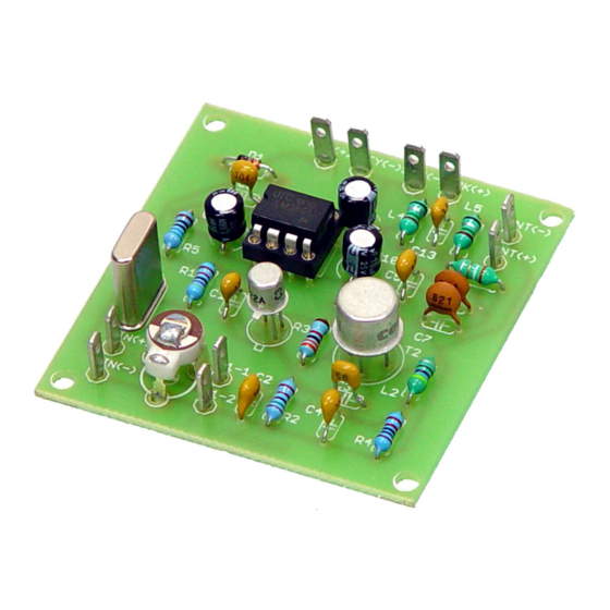
- Page 5 The board with the capacitors placed. Give special attention to soldering the electrolytic capacitors C9, C10 and C11 since they are polarized. The correct polarity is printed on the board. Finish the construction by soldering IC1's 8 pin base, D1, T1, T2. Take care regarding the placement of Transistors T1 and T2.
- Page 6 in it's correct place. TESTING Now it is time to check the functionality of your new QRP transceiver. Connect an appropriate antenna or dummy load at the antenna terminals of the transceiver. Connect a Morse key and an earphone or small speaker to the appropriate pins located on the board and finally connect a 9V battery on the 9V clip.
- Page 7 XTAL 20M (14.060 KHz) 8 PIN DIL SOCKET 9 VOLT BATTERY CLIP INPUT/OUTPUT PINS X 10 PCS HOW TO READ RESISTOR VALUES Resistor values are marked on the resistors by the means of color bands. Standard 5%, 10% or 20% tolerance resistors use a 4 color bands scheme while 1% and 2% use a 5 color bands scheme.
-
Page 8: Technical Assistance
HOW TO READ CAPACITOR VALUES Usually large value capacitors in the uF range have their value printed on them. Smaller value capacitors usually have two or three numbers printed on them. The first two numbers are the first two significant digits of the capacitors value and the third point is the multiplier. - Page 9 PARTS PLACEMENT...
- Page 10 RadiØKit-120 SCHEMATIC DIAGRAM...
- Page 11 Revisions There are no revisions for Radi0Kit-120 as yet.
Need help?
Do you have a question about the RadioKit-120 and is the answer not in the manual?
Questions and answers