
Subscribe to Our Youtube Channel
Summary of Contents for Noise Com UFX7000 Series
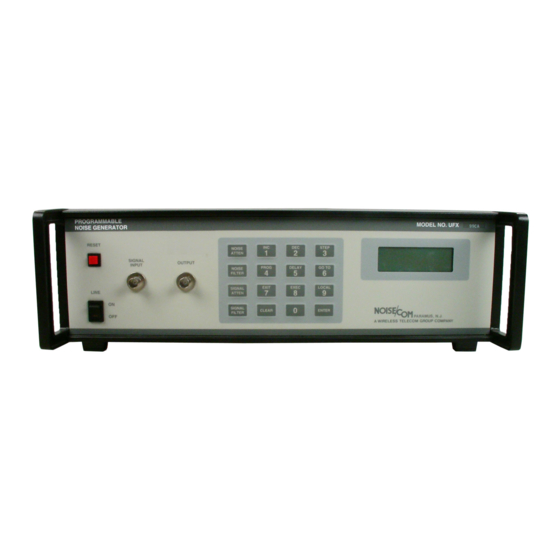
- Page 1 sales@artisantg.com artisantg.com (217) 352-9330 | Click HERE Find the NoiseCom UFX7103 at our website:...
-
Page 2: Table Of Contents
NOISE COM, INC. TABLE OF CONTENTS GENERAL INFORMATION Special Instructions Introduction Description of the Basic Unit Options and Optional Configurations SPECIFICATIONS Instrument Specification Functional Specifications Block Diagram III. INSTALLATION Initial Inspection GPIB (IEEE 488 BUS) Interconnection GPIB Address RS 232, RS 422, RS 423 Interconnection... -
Page 3: General Information
NOISE COM, INC. GENERAL INFORMATION SPECIAL INSTRUCTIONS SELECTION OF LINE VOLTAGE AND FUSES 1. Remove Power Cord. 2. Open access door to power entry module with a small screwdriver. 3. Pull fuse carrier out. Replace fuse with required one. (Fuse size marked on rear panel). -
Page 4: Introduction
Section I provides a description and option information for the Programmable Noise Generating Instruments. DESCRIPTION OF THE BASIC UNIT Noise Com, Inc. Series UFX7000 and UFX9000 Noise Generating Instruments represent state noise generators. Utilizing dedicated keys and a 4x20 LCD display the UFX series is both user friendly and powerful. -
Page 5: Options And Optional Configurations
NOISE COM, INC. OPTIONS AND OPTIONAL CONFIGURATIONS Programmable Noise Generating Instrument options include: Fine resolution attenuator .1db steps 0 - 127.9DB. Input Power 230V 50Hz. Rack Mounting Brackets (19" x 5¼"). Switching bandwidth by means of band limiting filters. Frequencies to be specified by customer. -
Page 6: Functional Specifications
NOISE COM, INC. FUNCTIONAL SPECIFICATIONS Volatile memory retain program parameters, GPIB address, serial baud rate user programmed control sequences Baud Rate : 0150,300,0600,1200,2400,4800 and 9600 to be used with optional serial interface ports data bits,no parity 1 stop bit). Time Delay: 0.1 to 999.9 seconds with 0.1 second... -
Page 7: Installation
If the instrument has been damaged in transit, notify the carrier as well as Noise Com, Inc. GPIB (IEEE 488 BUS Interconnection) only... -
Page 8: Gpib Address
NOISE COM, INC OPERATION INTRODUCTION The NOISE/COM PNGI uses a powerful single-chip microprocessor to accurately control the amplitude, bandwidth, and combining of its internal broad-band noise source and an externally applied user generated signal. Commands PNGI entered front-panel dedicated keypad. - Page 9 NOISE COM INC After brief delay, the MAIN INFORMATION DISPLAY will appear, similar to the display shown below: MANUAL MODE NA=127.9dB NF=1 SA=127.9dB SF=1 ST=000.1 P=000.0dB MANUAL MODE, on the top line, indicates that the PNG is ready to accept commands from the KEYPAD and has received...
- Page 10 NOISE COM, INC. INITIAL PNG CONFIGURATION first time the PNG is used, and whenever the Remote Communications requirements change, the 'LOCAL' Function should be selected from the Keypad. pressing this key as the first sequence (key interpretations sequence dependent), the following information screen will be displayed:...
- Page 11 NOISE COM, INC. FRONT PANEL CONTROLS Programming via the keypad: The PNGI can be directly programmed through the front panel keypad (see Figure 3) using simple data entry sequences. Internally the PNGI may have a maximum rf curcuit as follows:...
- Page 12 NOISE COM, INC. digits pressed keypad, they enter parameter display from the right and displace previously entered digits to the left. The parameter display may be reset to zero ('0000' or '0') by pressing the 'CLEAR' key. Invalid entries will not be accepted.
- Page 13 NOISE COM, INC. Invalid entries will not be executed. The PNG will automatically limit the Attenuation Value from '000.0' to themaximum value permitted by the PNG Type (typically '127.9' or '079.9'). PROGRAMMING NOISE FUNCTION SEQUENCES Through Keypad, PNG-III programmed with...
- Page 14 NOISE COM, INC. The number shown after 'PROG#:' defines the current PROGRAM Number (Film snippet number) being edited. Valid PROGRAM numbers are '0' through '9'. The number shown after 'STEP#:' defines the FRAME Number being edited within the current PROGRAM. Valid FRAME Numbers are '00' through '15'.
- Page 15 NOISE COM, INC. The cursor will point to the 'SEL._AT' field, indicating that the appropriate Attenuator, 'NOISE ATTEN' 'SIG.ATTEN' must selected. Upon pressing appropriate key, Program Edit Display will show: PROG#:1 STEP#:09 NOISE AT INC. At this time, the user may press 'ENTER' to accept the command,...
- Page 16 NOISE COM, INC. A graph of the Noise Attenuation resulting from the above program would appear as follows: ATTEN │ ┌─┐ ┌─┐ ┌─┐ (dB) │ ┌─┘ │ ┌─┘ │ ┌─┘ │ │ ┌─┘ │ ┌─┘ │ ┌─┘ │ │ ┌─┘...
- Page 17 NOISE COM, INC. As the above display will only be visible during execution of each Program Step, only DELAY steps will appear for a duration sufficient for viewing. REMOTE CONTROL OF THE PROGRAMMABLE NOISE GENERATOR All of the PNG Functions Programmable via the Front Panel Keypad...
- Page 18 NOISE COM, INC. Numeric values for Attenuation, Step Size and Time parameters may be entered in a 'free-format', and may include a decimal point where appropriate. Thus, 012.5, 12.5 and 0125 are equivalent, as are 012.0, 12.0, 12 and 0120.
- Page 19 NOISE COM, INC. Pn:mm NA12 Enters PROG#n FRAME#m into non- Volatile memory. The specific Command may be any that are Permissible for Keypad entry of Program Steps, plus the ability to specify a Step Size for the Signal Attenuator differs from...
- Page 20 NOISE COM, INC. The following sequence of instructions enters the same sequence of program steps described in the Keypad Programming example above. Note that specific character codes used represent Program Functions, and that all such Program Entry Commands must have the same opening format 'Pn:mm ' P0:00 NS002.0 cr...
- Page 21 NOISE COM, INC. TRIGGERING: T d1 [ d2 d3 d4 d5 ] When operating the PNG under control of a Remote Device, an Execution Trigger may be specified that will cause immediate (default) or deferred execution of the command. The values for...
- Page 22 NOISE COM, INC. Q: inQuiry The 'Q' command is issued by the controlling computer or terminal to solicit a Status Report of the current state of the PNG- III. Upon receiving the command, the PNG will respond by transmitting a string of ten (10) 4-digit numbers,...
- Page 23 NOISE COM, INC. PERFORMANCE VERIFICATION TEST EQUIPMENT Spectrum Analyzer, Hewlett Packard 8566B, 8557A, 8558B. Dynamic Signal Analyzer (FFT) Hewlett Packard 3561A. Power Meter, Hewlett Packard 432A. RF Voltmeter Hewlett Packard 3400A. (True RMS Voltmeter) Digital Plotter Hewlett Packard 7470A. Temperature Compensated Thermistor Mount Hewlett Packard 478A or 8478B.
- Page 24 Favorable 3-years Calibration Service Contracts are available. For further information, * * * Call Noise Com, Inc. at (201) 261-8797 * * * Pg 26 Document M016301 Rev. 2 2/26/03 Artisan Technology Group - Quality Instrumentation ... Guaranteed | (888) 88-SOURCE | www.artisantg.com...
- Page 25 NOISE COM, INC. VIII. WARRANTY Noise products warranted against defects materials and workmanship for a period of one year from the date of shipment. Noise Com, Inc. will, at its option, repair replace products that prove defective during warranty period,...
- Page 26 NOISE COM, INC. DUMMY LOAD PROGRAMMABLE NOISE ATTENUATOR SOURCE SWITCH 0-127 dB BASIC RF CIRCUIT FIGURE: 1 Page 29 Rev. 2 2/26/03 Document M016301 Artisan Technology Group - Quality Instrumentation ... Guaranteed | (888) 88-SOURCE | www.artisantg.com...
- Page 27 NOISE COM, INC. NOISE COM P/N 13567 RESET NOISE STEP ATTEN SIGNAL OUTPUT NOISE PROG DELAY GO TO INPUT FILTER SIGNAL EXIT EXEC LOCAL ATTEN LINE SIGNAL ON-OFF CLEAR ENTER FILTER NOISE/ C OM LAT DARK GREY Document M016301 Page 31 Rev.
- Page 28 NOISE COM, INC. SIGNAL OR NOISE SIGNAL OR NOISE OUTPUT Dummy Load Dummy Load FILTERS FILTERS User 1 dB ATTEN. 0.1 dB ATTEN. COMBINER 0.1 dB ATTEN. 1 dB ATTEN. Signal Input 2P8T SWITCH 0-127 dB 0- .9 0- .9...
Need help?
Do you have a question about the UFX7000 Series and is the answer not in the manual?
Questions and answers