Table of Contents
Advertisement
Quick Links
B06 20 243 E-EN
page 1 / 23
Installation and
09. 2010
Maintenance Manual
ABT 75 G / ABT 90
G
Installation and Maintenance
Manual
CB8-E
Alterations reserved
Siegerland Bremsen – Emde GmbH & Co. KG – Auf der Stücke 1-5 – D-35708 Haiger, Germany
Tel.: +49 2773 94000 – Fax: +49 2773 9400-10 – e-mail:
–
info@sibre.de
www.sibre.de
D:\Daten\dat_word\sibre\CB8\CB8-E-100
09-2010.doc
Advertisement
Table of Contents

Summary of Contents for SIBRE CB8-E Series
- Page 1 Installation and Maintenance Manual CB8-E Alterations reserved Siegerland Bremsen – Emde GmbH & Co. KG – Auf der Stücke 1-5 – D-35708 Haiger, Germany Tel.: +49 2773 94000 – Fax: +49 2773 9400-10 – e-mail: – info@sibre.de www.sibre.de D:\Daten\dat_word\sibre\CB8\CB8-E-100 09-2010.doc...
-
Page 2: Table Of Contents
Spare parts Trouble shooting Disposal Alterations reserved Siegerland Bremsen – Emde GmbH & Co. KG – Auf der Stücke 1-5 – D-35708 Haiger, Germany Tel.: +49 2773 94000 – Fax: +49 2773 9400-10 – e-mail: – info@sibre.de www.sibre.de D:\Daten\dat_word\sibre\CB8\CB8-E-100 09-2010.doc... -
Page 3: General Instructions
CB8-E General Instructions PLEASE NOTE The present manual is only valid in connection with SIBRE document General Notes B 06 20 176 E. The present manual is an integral part of the brake as supplied. It should always be kept near the brake. -
Page 4: Symbols Used In The Operating Instructions
Any work carried out on the brake, which is not mentioned in this manual, should be regarded as repair. In such cases, please contact your local SIBRE supplier. 2.2 Symbols used in the operating instructions The important instructions contained in the operating instructions and relating to both safety and... -
Page 5: Technical Data
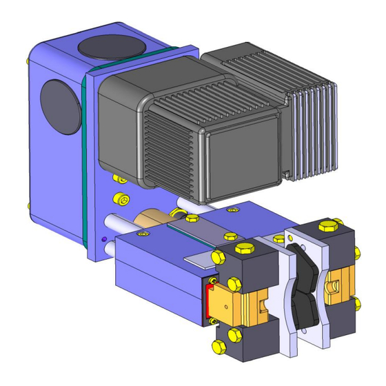
B06 20 243 E-EN page 5 / 23 Installation and Maintenance Manual 09.2010 CB8-E Technical Data 3.1 Description The CB8-E (see figure 1 and figure 2) is designed to transfer a braking torque to a brake disc in order to stop the rotation of the brake disc or to prevent the brake disc from rotating when stopped (parking brake). - Page 6 B06 20 243 E-EN page 6 / 23 Installation and Maintenance Manual 09.2010 CB8-E sensor thrustor „pad wear” retension manual spring release roller release lever sensor „brake open” stud square part with integrated readjusting unit adjustable spring brake spring chamber lever Fig.
- Page 7 B06 20 243 E-EN page 7 / 23 Installation and Maintenance Manual 09.2010 CB8-E Spring chamber: Allows the continuous adjustment of spring torque, by adjusting the preload of the spring. Protection cover: The protection cover avoids the fouling of the release mechanism and guarantees the operational reliability of the brake even under rough environmental conditions.
-
Page 8: Dimensions
B06 20 243 E-EN page 8 / 23 Installation and Maintenance Manual 09.2010 CB8-E 3.2 Dimensions protective cover, manual release, limit switches „brake open“ & „pad wear“ Options thrustor mounting position selectable between “L”, “T” or “R” = disc thickness in mm, Standard = 20, optional: 12.7; 16; 25; 30 ØD2 = outer disc diameter in mm linings:... -
Page 9: Installation
B06 20 243 E-EN page 9 / 23 Installation and Maintenance Manual 09.2010 CB8-E Installation 4.1 Scope of supply The scope of supply is set out in the shipping documents. Completeness must be verified upon receipt. Any damage incurred in transit and/or missing parts must be reported immediately in writing. The CB8-E brake is supplied ready to install. -
Page 10: Cleaning The Brake Disc
Brake linings can be supplied with several lining materials in two different types, depending on the brake size and/or application. All brake linings supplied by SIBRE are asbestos free and free of lead. In general two types of lining materials are available: ... -
Page 11: Mounting Of The Brake - Initial Setup On Site
B06 20 243 E-EN page 11 / 23 Installation and Maintenance Manual 09.2010 CB8-E Sinter brake linings are less sensitive to dirt, grease and oil and can in some cases - where not fully soaked up with oil - be cleaned with solvent and re-used. WARNING Solvent cleaners can be flammable, poisonous and can cause burns. - Page 12 B06 20 243 E-EN page 12 / 23 Installation and Maintenance Manual 09.2010 CB8-E WARNING The manual release is spring biassed to realize an auto-kickback functionality. The activated manual release will jump back in its initial position automatically by spring force, when the brake is released by solenoid the next time.
-
Page 13: Manual Release
B06 20 243 E-EN page 13 / 23 Installation and Maintenance Manual 09.2010 CB8-E CAUTION The full torque is only generated after bedding in of the linings. The contact pattern must be minimum 70% for operation. 4.9 Manual release The disc brake CB8 is provided with an eccentric manual release in series. The handling of the manual release is carried out as follows: Remove the sidewise cap (figure 7a) Rotate the eccentric shaft clockwise until the indexed position is reached (figure 7b). -
Page 14: Adjustment Of Reserve Stroke
B06 20 243 E-EN page 14 / 23 Installation and Maintenance Manual 09.2010 CB8-E 4.10 Adjustment of reserve stroke The reserve stroke avoids, that the brake gets "on block" position and no more braking force is transmitted to the disc any more. Without counteraction the reserve stroke would decrease with increasing lining wear. -
Page 15: Adjustment Of Brake Torque
B06 20 243 E-EN page 15 / 23 Installation and Maintenance Manual 09.2010 CB8-E cover with sealing square part control window Fig. 9: Checking the reserve stroke directly at the square part 4.11 Adjustment of brake torque The clamping force between the linings and the adjustable disc and so the brake torque is created by a spring... - Page 16 B06 20 243 E-EN page 16 / 23 Installation and Maintenance Manual 09.2010 CB8-E PLEASE NOTE Increasing the overhang will decrease the spring preload and so the clamping force / brake torque. Decreasing the overhang will increase the spring preload and so the clamping force / brake torque.
-
Page 17: Limit Switches
B06 20 243 E-EN page 17 / 23 Installation and Maintenance Manual 09.2010 CB8-E 4.12 Limit switches Optional the CB8 can be equipped with several kind of sensors. “Pad wear” An optional inductive limit switch (see figure 1 and figure 2) allows to detect lining wear. With increasing lining wear the rotating angle of the two brake levers increases, too, when the brake is closed. -
Page 18: Maintenance
B06 20 243 E-EN page 18 / 23 Installation and Maintenance Manual 09.2010 CB8-E Maintenance 5.1 Replacing the brake linings CAUTION When the linings are worn, they must be replaced. Worn out linings can cause a failure of the brake. The maximum allowed lining wear of 5 mm per side is reached, when the remaining thickness of the lining has reached a value of 2 mm for sinter linings or 7 mm for organic linings. - Page 19 B06 20 243 E-EN page 19 / 23 Installation and Maintenance Manual 09.2010 CB8-E Turn the threaded borehole inside the free wheel ring into the upper position by pumping the adjusting nut with the hexagon key Ø4 mm. Mount threaded pin (figure 12). free wheel ring with threaded...
-
Page 20: Replacing Other Components
5.2 Replacing other components Although some minor components might be replaced with the brake mounted on site, generally it is highly recommended to take the brake to a SIBRE workshop for repairs. For removing the brake follow the instructions given in §4.13. -
Page 21: Spare Parts
B06 20 243 E-EN page 21 / 23 Installation and Maintenance Manual 09.2010 CB8-E 5.4 Spare parts Maintaining a supply of the most important spare and wear parts at the location is an important factor in assuring continuous readiness of the brake for use. For required spare parts see figures 15 and 16. When ordering spare parts please advice: ... -
Page 22: Trouble Shooting
SIBRE for refurbishment opened many years in operation... -
Page 23: Disposal
The operator and / or user are responsible for the proper disposal of the brake and the associated components. If any doubts about the correct disposal exist, please do not hesitate to contact SIBRE or your local dealer or regional disposal enterprises for further information.
Need help?
Do you have a question about the CB8-E Series and is the answer not in the manual?
Questions and answers