
Subscribe to Our Youtube Channel
Summary of Contents for Plafolift PHD 26
- Page 1 Rev. 2020-02-18 OPERATOR MANUAL VERIFYED BY: ________________ DATE: ________________...
- Page 2 Our mission The mission of Plafolift International is to improve productivity for business’ that require solutions above and beyond standard lifting operation. This goal is achieved by listening to customer needs and requirements. Our innovation capacity and technical knowhow is put to work to constantly improve our products.
- Page 3 Preface This motorized elevated work platform is the result of the technological improvement of Plafolift International and the quality care in conception, engineering and manufacturing. All the information, including illustrations and characteristics, comprised in this manual is based on data available at the moment this manual was written. It is essential that all maintenance or operating personnel, has read and understood the information in this manual.
-
Page 4: Table Of Contents
USER MANUAL Rev. 2020-02-18 Table of content ......................... 7 ENERAL PRESENTATION SECURITY ............................. 9 GENERAL ............................9 Work area inspection ........................10 At all times ........................... 10 During use ........................... 11 2.4.1 Fall protection ........................11 2.4.2 Tip-over protection ....................... 11 2.4.3 Slopes and ditches ...................... - Page 5 ANUAL Rev. 2020-02-18 ............................32 PERATION Description ........................... 32 5.1.1 Engine start-up ........................33 5.1.2 Safety notification ........................ 34 Access door ..........................34 Folding guardrails ........................34 Using the extendable deck (retractable portion) ................35 Lateral extension guardrails ......................38 Control panel ..........................
- Page 6 USER MANUAL Rev. 2020-02-18 7.9.7 Hydraulic reservoir ....................... 67 7.9.8 Pump ........................... 67 7.9.8.1 Pump start-up ........................67 7.9.8.2 Pump maintenance ......................68 7.9.9 Hydraulic adjustment procedure ..................69 7.9.9.1 Start-up ..........................69 7.9.9.2 Master bloc safety valve ....................69 7.9.9.3 Pump safety valve ......................
-
Page 7: General Presentation
ANUAL Rev. 2020-02-18 ENERAL PRESENTATION... - Page 8 USER MANUAL Rev. 2020-02-18...
-
Page 9: Security
Never alter or modify the equipment without consent from Plafolift International. Modifications could result in equipment damage and put operator and ground personnel in danger. This equipment is manufactured to meet safety standard CAN B 354.2-01 – Self Propelled elevated work platform. -
Page 10: Work Area Inspection
USER MANUAL Rev. 2020-02-18 The following pages enunciate important safety rules that must be followed when operating or performing maintenance on this equipment. Failure to abide by these rules can result in damage to the equipment, injury to personnel or even death. Safe driving includes ... -
Page 11: During Use
ANUAL Rev. 2020-02-18 2.4 During use 2.4.1 Fall protection Even if the guardrail system provides fall protection, rules and regulations related to the workplace may require additional fall protection. Users and operators must conform to laws in effect. Any supplementary fall protection system must be fixed to a guardrail lanyard anchorage point. -
Page 12: Clearance Height
USER MANUAL Rev. 2020-02-18 2.4.5 Clearance height The operator must ensure that height clearance is sufficient to avoid contact with any obstacle, equipment or electrical wiring. 2.4.6 Electrical hazard If the platform is not electrically grounded, precautions must be taken. Operator needs to keep required minimum distance between platform and high tension wires. -
Page 13: Precaution Related To Other Motorized Vehicles
ANUAL Rev. 2020-02-18 2.4.8 Precaution related to other motorized vehicles Working zone of the platform must be bordered with flags, security cords, flashing lights or fences when other motorized vehicles are working nearby. 2.4.9 Load distribution The elevated work platform (including lateral and extendable floor) must not be used to support loads spreading beyond the external edges of the platform. -
Page 14: Incorrect Stabilization Of Platform
The motorized elevated work platform must not be operated or raised on trucks, trailers, railroad vehicles, floating vessels, scaffolds or similar equipment unless written approval is provided by Plafolift International 2.4.16 Travel speed Travel speed in lowered position is 2.5 km/h (1.5 mph) and is limited to 0.9 km/h (0.56 mph) when platform is deployed. -
Page 15: Security Device Modifications
ANUAL Rev. 2020-02-18 2.4.18 Security device modifications Locking or security devices must never be altered or de-activated Failure to following this safety rule could result in serious injury or death 2.4.19 Deck of unit stuck If the deck of the equipment is stuck in elevated position, first of all, check if the security prop is not blocking the scissor. -
Page 16: Safe Work Practices
USER MANUAL Rev. 2020-02-18 2.4.24 Safe work practices Safe operation is very important. To ensure safe work practices, operator must (mandatory) Be aware of equipment maximum load capacity Inspect equipment before each use, as specified by the manufacturer ... -
Page 17: Maintenance
Hydraulic safety valve adjustments must never be modified. All replacement parts must be original. Any substitution could result in a warranty void by Plafolift International Avoid placing body parts in the way of equipment movement Never smoke during refueling operations ... -
Page 18: Responsibilities
2.7 Responsibilities Plafolift International is not responsible for any work or alteration performed on this equipment without written authorization. Plafolift International is not responsible for inadequate or abusive use of this equipment. - Page 19 ANUAL Rev. 2020-02-18...
- Page 20 USER MANUAL Rev. 2020-02-18...
- Page 21 DEM_YA10622 6” x 4” Aluminum Rear right identification plate section of the floor 7” x 4” TDS YA1028 Plafolift logo Front panel of diesel compartment Plafolift logo Front and rear of floor, each side 21” x 5” TDS YA1100 of second...
- Page 22 USER MANUAL Rev. 2020-02-18 PLACARD DESCRIPTION LOCATION SIZE Extension floor maximum capacity warning 9” x 4” TDS YA1165 Extension floor guardrail Lateral bar extension maximum capacity warning Left side of 9” x 4” TDS YA1167 guardrail before entering the lateral floor 6”...
- Page 23 ANUAL Rev. 2020-02-18 PLACARD DESCRIPTION LOCATION SIZE ID and electrical information on floor Rear bumper, 6” x 2” TDS YA1294 electrical outlet near extension plug ID and electrical information on Front bumper 6” x 2” TDS YA1295 equipment heater near block heater plug Electrocution, tipping, 10”...
- Page 24 USER MANUAL Rev. 2020-02-18 PLACARD DESCRIPTION LOCATION SIZE Owner manual Document 6” x 3” TDS YA1415 location holder Maximum lateral force and wind speed Both entrances 7” x 5” TDS YA1416 warning of platform Horn / authorization Joystick control 3” x 3” TDS YA1417 button location Glow plugs / start...
- Page 25 ANUAL Rev. 2020-02-18 PLACARD DESCRIPTION LOCATION SIZE Safety prop support Cross tube of 4” x 4” placement scissor aligned TDS YA1404 with prop Emergency lowering 3” x 4” handle location Back of chassis TDS YA1420 Cold start pre-heat mandatory period Top of joystick 2”...
-
Page 26: Responsibilities
USER MANUAL Rev. 2020-02-18 ESPONSIBILITIES 3.1 General User and operator have to read and understand all safety procedures before operating this equipment. 3.2 Operator training 3.2.1 Training requirements Only personnel trained on inspection, operation and driving can operate this equipment. Training must include the following topics: ... -
Page 27: Recurrent Training
ANUAL Rev. 2020-02-18 3.2.4 Recurrent training Operators must have recurrent training at pre-determined intervals. Training must be delivered by a competent authority. 3.2.5 Training Supervision Training must be done under the supervision of a qualified operator in a safe and open area free of obstructions and obstacles. -
Page 28: Inspection
USER MANUAL Rev. 2020-02-18 NSPECTION 4.1 General This equipment must be inspected, tested and maintained in accordance with recommendations stated in this manual. See the Inspection section. Any problem or defect related to safety or function must be repaired before putting the equipment in service 4.2 Inspection classifications Inspections are classified in 4 different categories (see list below) :... -
Page 29: Pre-Start Inspection
ANUAL Rev. 2020-02-18 4.2.1 Pre-start Inspection To avoid injury, make sure the equipment engine is shut down before performing inspection Before a start-up, the operator must perform a visual inspection to insure the equipment is safe. Routine check-up must include: ... -
Page 30: Rate
USER MANUAL Rev. 2020-02-18 4.2.4.1 Rate The structural inspection must be performed 10 years after the manufacturing date and every 5 years afterward If structural integrity or stability has been potentially jeopardized in an incident. For example; an electrical shock, a tip-over, a free fall protection incident, an overload, a collision or an impact. -
Page 31: Inspection Reports
ANUAL Rev. 2020-02-18 4.2.4.4.3 Stability test In case of modification or suspected damage, a stability test must be performed under the authority of a licenced engineer as per CSA standard B354.02-01. 4.3 Inspection reports The owner must keep records of all information related to regular and annual inspections, maintenance, repair and part replacement. -
Page 32: Operation
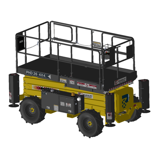
USER MANUAL Rev. 2020-02-18 PERATION 5.1 Description The purpose of this motorized elevated work platform is to position personnel and their tools to work required heights. The base control panel is located inside the electrical compartment. The joystick is placed on the deck’s guardrail. From the base control panel, the operator can command the four outriggers as well as the raising and lowering functions. -
Page 33: Engine Start-Up
ANUAL Rev. 2020-02-18 5.1.1 Engine start-up Plug the hydraulic/engine/battery heater at least 1 hours before a -15°C and below cold start 1. Before starting the engine, locate the emergency stop switch; an emergency shutdown might be necessary at any time. 2. -
Page 34: Safety Notification
USER MANUAL Rev. 2020-02-18 5.1.2 Safety notification To ensure safety, limit switches must never be bypassed. 5.2 Access door 1. Disengage the chain hook from the guardrail eye nut enter exit platform 5.3 Folding guardrails Step 1 Step 2 Remove the pin on each side of the Remove the butterfly nut on each side, if guardrail. -
Page 35: Using The Extendable Deck (Retractable Portion)
ANUAL Rev. 2020-02-18 Step 3 Fold the guardrail toward the floor and replace the nuts and the pins. To put the guardrail in its original position, repeat steps 1 to 3 backwards. 5.4 Using the extendable deck (retractable portion) The following steps describe how to retract the extendable deck. To extend the deck, follow the steps backwards. - Page 36 USER MANUAL Rev. 2020-02-18 Step 4 Remove the pin of the guardrail to pivot the manipulating arm Step 5 Pull on the manipulating arm to extend the floor as shown on the image above...
- Page 37 ANUAL Rev. 2020-02-18 Step 6 Make sure the spring-loaded latch is in place in the lock hole of the floor (see image on the left) Step 7 Pivot the manipulating arm toward the guardrails, lower the manipulating arm handle and replace the two pin.
-
Page 38: Lateral Extension Guardrails
USER MANUAL Rev. 2020-02-18 5.5 Lateral extension guardrails Fall protection equipment: The elevated platform guardrails provide fall protection. Safety laws and standards in your locality might require additional fall protection. Operators have to wear a certified harness when using the lateral extension. The extension must be constituted of unmodified, NLGA certified scaffolding lumber no more than 14 ft (4.25 meters) long. - Page 39 ANUAL Rev. 2020-02-18 Step 1 Step 2 Pull the spring-loaded latch to free the Slide the lateral bar until the hole is lateral bar. aligned with the latch pin. Step 3 When hole is aligned, lock in place. Repeat steps 2 to 4 for the other lateral bars.
- Page 40 USER MANUAL Rev. 2020-02-18 Step 4 Unfold the lateral guardrails on each side of the lateral floor. Lift and rotate to a 90° angle.
- Page 41 ANUAL Rev. 2020-02-18 Step 5 Open the access door to install the scaffold on the lateral bars. Step 6 Configuration must be similar to the above drawing. Use the angle supports provided with the unit on each side of the lateral bars. Use retaining pins to keep the scaffolding beams secured.
-
Page 42: Control Panel
USER MANUAL Rev. 2020-02-18 5.6 Control panel The elevated platform has 2 control panels One located in the electrical compartment of the chassis The second is installed on one of the guardrails and is accessible from the deck 5.6.1 Details of the control panel from the electrical compartment of the chassis... - Page 43 ANUAL Rev. 2020-02-18 # Item Item Function Toggle Activates the raising and lowering functions of the platform. This switch has priority over the same switch on the deck’s switch control panel. To activate, you must engage the deadman switch (#6) at the same time. Toggle Activates the deployment of the front left stabilizer.
-
Page 44: Detail Of Control Panel From The Deck
USER MANUAL Rev. 2020-02-18 5.6.2 Detail of control panel from the deck... - Page 45 ANUAL Rev. 2020-02-18 # Item Item Function Ignition/contact Contact switch for the start key: 3 pole spring loaded on 2 switch axes. Before start-up, make sure the emergency stop buttons are disengaged on both control panels (chassis and deck). In cold weather, turn the key counter clockwise to the pre- heat position.
- Page 46 USER MANUAL Rev. 2020-02-18 Rapid mode allows driving at maximum speed when the platform is in the stowed position. Traction mode gives maximum torque to the wheels and reduces speed for a more precise movement. Toggle switch Allows choice of the action mode. Upper position: activates proportional raising of the platform Lower position : activates traction and steering...
-
Page 47: Motorized Elevated Work Platform Positioning
ANUAL Rev. 2020-02-18 5.7 Motorized elevated work platform positioning 5.7.1 Ground conditions Some terrain conditions must be avoided, or partially corrected, to allow the platform to work safely and properly. Before using the equipment the operator must ensure the site is free of any danger like strong slopes, loose soil, obstacles on the ground or in height. -
Page 48: Raising And Lowering Of The Platform
USER MANUAL Rev. 2020-02-18 5.9.2 Raising and lowering of the platform Ensure no one is near the scissor when starting the raising or lowering procedure. 1. Make sure the safety prop is not blocking the scissor before lowering the platform. If in place when lowering the platform, serious structural damage could occur. -
Page 49: Loading The Platform
ANUAL Rev. 2020-02-18 Do not increase the lateral surface of the platform exposed to the wind. The augmentation would result in a reduction in stability of the platform Select the driving mode : speed or traction (fast or slow) ... -
Page 50: Safety
USER MANUAL Rev. 2020-02-18 5.13 Safety a) It is forbidden to install a tarp, shelter, tarpaulin or any other device on the unit when in operation; stability could be jeopardized. b) When work is being performed close to an electrical line, make sure to respect the minimum approach distance in relation to the voltage of the electrical line. -
Page 51: Emergency Procedures
Incident reporting Plafolift International must be informed of any incident involving this motorized elevated work platform or any other equipment manufactured by Plafolift International, even if no apparent damage or injury to personnel has occurred. Plafolift International must be informed of all details concerning the incident. -
Page 53: Maintenance Procedure
If these rules are not followed, injury to personnel or mechanical damage could occur. All replacement parts must be original. Any substitution could result in a warranty void by Plafolift International. Only qualified and competent personnel should perform these maintenance tasks. -
Page 54: Hydraulic System Precautions
USER MANUAL Rev. 2020-02-18 7.3 Hydraulic system precautions equipment’s hydraulic systems operate potentially dangerous pressures. Great effort should be made relieve system pressure before disconnecting or removing any component of the system. 1. Always retract the stabilizers before performing repairs. 2. -
Page 55: Procedure To Support The Platform
ANUAL Rev. 2020-02-18 7.4.1 Procedure to support the platform Step 1 Remove all material or load from the platform. Raise the platform to be able to rotate the safety prop around its pivot points as shown above. - Page 56 USER MANUAL Rev. 2020-02-18 Step 2 Lower the platform until the distance between the upper and the lower pivot points is approximately 25". Step 3 Always use the gravity descent control system (emergency descent on the back of the chassis) when the safety prop is in place.
-
Page 57: Procedure For Disengaging The Security Bar
ANUAL Rev. 2020-02-18 7.4.2 Procedure for disengaging the security bar When the maintenance work is completed, follow this procedure to disengage the safety prop. Step 2 Step 1 Continue the rotation until the prop Pull out the emergency stop button comes in contact with the square tubing of the scissor. -
Page 58: Safety Advice
USER MANUAL Rev. 2020-02-18 7.5.1 Safety advice Your safety and the safety of your co-workers is priority when performing maintenance on this equipment. You must always be aware of the weight of its components. Never attempt to move heavy components without the appropriate tooling (overhead bridge crane, forklift) Do not leave heavy components in unstable positions. -
Page 59: Gasket
ANUAL Rev. 2020-02-18 Lubricate ball bearings as recommended by the manufacturer before installing them. When installing a ball bearing in an opening, you must apply pressure on the external casing of the bearing. When installing the bearing on a shaft, you must apply pressure on the internal casing of the bearing. -
Page 60: Lubrication
USER MANUAL Rev. 2020-02-18 7.6 Lubrication The grease used for lubrication (see the lubrication diagram on the next page) is ® ® SINTO SINEP 2 . It is important that all pivot points be always lubricated. ® Using other greases than SINEP 2 can cause pivot points to jam from ®... - Page 61 ANUAL Rev. 2020-02-18...
-
Page 62: Engine
USER MANUAL Rev. 2020-02-18 ® Lubrication points (SINTO SINEP 2 Item Description Raising hydraulic cylinder grease nipple Link tube between both sides of scissor grease nipple Scissor pivot grease nipple Support grease nipple Scissor wheel grease nipple Link pivot between pin and base/platform grease nipple Extension roller bearing grease nipple Forward steering pivot wheel grease nipple Stabilizer foot grease nipple... -
Page 63: Pump Adapter
ANUAL Rev. 2020-02-18 7.8 Pump adapter The pump adapter is a maintenance free component. In case of faulty or damaged gear, follow the subsequent procedure to replace any part Remove the pump Replace the damaged component Apply thread lock (Loctite) on the bolt threads ... -
Page 64: External Leak
These repairs can only be performed by qualified and trained personnel aware of the precautions specific to cylinders manufactured by Plafolift International. Maintenance of hydraulic components must be performed in a clean environment with the proper tooling. -
Page 65: Heat Generation
ANUAL Rev. 2020-02-18 7.9.3 Heat generation Internal leaks result in pressurized fluid returning to the hydraulic tank. Constant flow causes temperature of the hydraulic fluid to rise. The amount of heat generated is consequent with the internal pressure and volume in the hydraulic system. If excessive heat is generated in the hydraulic system, the root cause must be found and corrected as soon as possible. -
Page 66: Hydraulic Fluid Specifications
USER MANUAL Rev. 2020-02-18 7.9.5 Hydraulic fluid specifications Hydraulic fluid condition plays an important role in keeping the equipment serviceable for a long period and in avoiding problems on hydraulic components. Proper grade, temperature and filtering will help to keep high performance. The specified hydraulic fluid contains additives preventing corrosion, worn and foaming. -
Page 67: Return Filter
ANUAL Rev. 2020-02-18 7.9.6.2 Return filter The return filter’s function is to clean all hydraulic fluid circulating in the system. It is the last component of the system’s loop. The return filter is located in the hydraulic compartment on the left side of the unit. Fluid is flowing to the filter through the return hose to the tank. -
Page 68: Pump Maintenance
USER MANUAL Rev. 2020-02-18 Failure to follow said recommendations, the pump will suffer damage very quickly, even after only a few seconds. 7.9.8.2 Pump maintenance Cavitation and air infiltration are the main causes of pump damage. These conditions can be prevented by identifying and correcting problems as soon as they arise. Cavitation happens when oil on the suction line does not fill all exposed cavities of a pump. -
Page 69: Hydraulic Adjustment Procedure
For more information on maintenance and repair of the pump, contact the service department of Plafolift International. 7.9.9 Hydraulic adjustment procedure The following sections detail procedures to follow for hydraulic system adjustments. -
Page 70: Raising Counterbalance
USER MANUAL Rev. 2020-02-18 7.9.9.6 Raising counterbalance Cartridge 4.5:1 pre-adjusted at 3500 PSI. 7.10 Low speed in raised position The low speed in raised position is electronically limited. 7.11 Traction counterbalance adjustment Traction counterbalances are factory adjusted and must never be modified. 7.12 Hydraulic cylinder 7.12.1 Raising cylinder replacement procedure Raising cylinder removal... -
Page 71: Repair Procedure
ANUAL Rev. 2020-02-18 Extend the cylinder shaft until aligned with the attachment brackets. Install the pivot pin through the attachment bracket and the rod end. Secure it with a bolt Start the engine of the unit. Remove and stow the safety prop as specified in the safety prop procedure of section 7.4. -
Page 72: Cleaning And Inspection
USER MANUAL Rev. 2020-02-18 7.12.2.2 Cleaning and inspection Clean all the hydraulic cylinder components with the appropriate cleaning solvent. Inspect the cylinder strut for damage: scratches, cracks or warp. If any of these defects is detected, replace the strut. ... -
Page 73: Planetary And Brake
ANUAL Rev. 2020-02-18 Carefully slide the piston on the cylinder strut. Make sure that the O-ring are not damaged and in place Hold firmly the strut in a clamp Apply Loctite #242 adhesive on the strut thread and torque the nut on the strut ... -
Page 74: Electrical Components
USER MANUAL Rev. 2020-02-18 7.14.2 Electrical components Internal connections and all connections to valves, switches or relays are shown on the electrical diagram in the parts catalogue. Main electrical components are described in this section. 7.14.3 Control panel The control panel is installed on the platform guardrail and includes an ignition key, an emergency stop switch, a joystick and toggle switches. -
Page 75: Storage
ANUAL Rev. 2020-02-18 It’s important to perform a level adjustment of the switch at least every 6 months to ensure proper function. Adjustment of the tilt switch: Position the unit on a flat, compact and perfectly level surface Level the base of the switch with the three nuts until the bubble is in the middle of the bull’s-eye indicator Apply pressure on each corner, one at a time. -
Page 77: Quipment Specifications
8.1 Description This motorized elevated work platform is compliant with CSA standard CAN B 354.2-01, its trademark is PLAFOLIFT INTERNATIONAL and it is used on construction sites. This unit is designed to operate on compacted surfaces to position in height working conditions: workers, tooling and materials (maximum capacity of 1500 lb). -
Page 78: Technical Specifications
SER MANUAL Rev. 2020-02-18 8.3 Technical specifications Specification PHD26 Wheelbase 2,13 m Front wheel wheelbase 1,77 m 5' 9 5/8" Rear wheel wheelbase 1,53 m 5' ¼" 32’-3’’ Maximum height 9,75 m 26’ Platform height in raised position 7,93 m 5’-6"... -
Page 79: Hydraulic System
SER MANUAL Rev. 2020-02-18 8.4 Hydraulic system Forward and reverse movement and steering 2700 PSI Main overpressure valve 3000 PSI Raising movement 2400 PSI Lowering movement 1400 PSI Cylinders on the motorized elevated work platform are used for stabilization, raising and lowering function (master cylinder) and for steering. -
Page 80: Brakes
SER MANUAL Rev. 2020-02-18 8.5.2 Brakes The motorized elevated work platform is equipped with integrated brakes in each planetary gearbox. The brake system is engaged when oil supply is stopped to the hydraulic motors. 8.5.3 Exhaust The motorized elevated work platform is equipped with a maintenance free exhaust system. - Page 81 SER MANUAL Rev. 2020-02-18 For continuous improvement of this document, please advise Plafolift international if any errors are found in the manual.
-
Page 82: Unit Adjustment Parameters
SER MANUAL Rev. 2020-02-18 NIT ADJUSTMENT PARAMETERS The following chart lists factory manufacturing adjustments. Those parameters must be inspected and adjusted if needed by trained and qualified personnel only. Adjustment parameters – elevated platform Raising and lowering overpressure relief valve (PSI) Raising speed, full throttle engine (sec.) Lowering speed, full throttle engine (sec.) Lowering speed, emergency descent (sec.) -
Page 83: Warning On Tire Pressure And Specifications
SER MANUAL Rev. 2020-02-18 ARNING ON TIRE PRESSURE AND SPECIFICATIONS Air pressure can affect stability. Temperature changes can affect air pressure. It is important to visually inspect all tires for proper inflation prior to use. Tires should be checked by end user on a daily basis. Tire air pressures must be checked weekly with a calibrated gauge. -
Page 84: Entering And Leaving The Platform In Raised Position
NTERING AND LEAVING THE PLATFORM IN RAISED POSITION To the attention of: Equipment safety supervisor. Subject: Entering and leaving Plafolift International platform in raised position. Before any raising operation, risk assessment related to the equipment and local laws on working sites should be performed. Not following this procedure could result in injury or death to personnel. -
Page 85: Inspection
SER MANUAL Rev. 2020-02-18 10 I NSPECTION Read and follow the instructions below 10.1 Inspection (DAILY) Frequency Daily: Visual inspection must be done by the operator at each shift start. Daily inspection (OPERATOR) Only the daily inspection specified in this manual can be performed by the operator. 10.2 Inspection (PERIODIC &... - Page 86 SER MANUAL Rev. 2020-02-18 Page 1 Daily inspection of 3 Motorized elevated work platform B354.2-01 standard, article 5.3.2 Brand : Serial number : Model : Year : Leaseholder: Inspection date : Owner : Inspected by : Defective Prior to engine start-up check: Corrected Diesel fuel, Engine oil, Hydraulic fluid, Engine coolant –...
- Page 87 SER MANUAL Rev. 2020-02-18 Page 2 Daily inspection of 3 Motorized elevated work platform B354.2-01 standard, article 5.3.2 Defective Prior to engine start-up: Corrected Electronic controller (electrical compartment) correctly fastened, all wires connected, no visible damage. Scissor – no apparent damage, cracked welding, distortion or excessive wear.
-
Page 88: Daily Inspection
SER MANUAL Rev. 2020-02-18 Page 3 Daily inspection of 3 Motorized elevated work platform B354.2-01 standard, article 5.3.2 Defective Safety devices: Corrected Raising function is disabled if only one stabilizer is lowered. Raising function is available only if the 4 stabilizers are deployed on solid ground or if all stabilizers are retracted. -
Page 89: Periodic Inspection (200 Hours Or 3 Months)
SER MANUAL Rev. 2020-02-18 Periodic inspection (200 hours or 3 months) Motorized elevated work platform B354.2-01 standard, article 5.3.2 Brand : Serial number : Model : Year : Locator : Inspection date : Owner : Inspected by : Defective After 200 hours of operation, inspect: Corrected All points from the daily inspection report Battery (electrical compartment): Electrolyte levels are... -
Page 90: Annual Inspection (700 Hours Or 12 Months)
SER MANUAL Rev. 2020-02-18 Annual inspection (700 hours or 12 months) Motorized elevated work platform B354.2-01 standard, article 5.3.2 Brand : Serial number : Model : Year : Locator : Inspection date : Owner : Inspected by : Defective After 700 hours of operation, inspect : Corrected All points from the daily inspection report All points from the periodic inspection report... - Page 91 SER MANUAL Rev. 2020-02-18 Inspection and repair report Date Comments...
- Page 92 SER MANUAL Rev. 2020-02-18 Inspection and repair report (continuation) Date Comments...
-
Page 93: Appendices
SER MANUAL Rev. 2020-02-18 APPENDICES... - Page 94 De même pour tout accident causé par la manipulation de charges excédant les limites de l'équipement. Si un tel accident se produisait, une preuve que la charge était bel et bien dans les limites admissibles reviendra être fournie. / In no case will Plafolift International be accountable for damages caused by poor usage of the equipment.
- Page 113 THE INFORMATION CONTAINED IN THIS DRAWING IS THE SOLE PROPERTY OF PLAFOLIFT INTERNATIONAL DIVISION OF 10006521 Canada inc. ANY REPRODUCTION IN PART OR AS A WHOLE WITHOUT THE WRITTEN PERMISSION OF PLAFOLIFT TITRE: INTERNATIONAL DIVISION OF 10006521 Canada inc IS PROHIBITED.
- Page 114 THE INFORMATION CONTAINED IN THIS DRAWING IS THE SOLE PROPERTY OF PLAFOLIFT INTERNATIONAL DIVISION OF 10006521 Canada inc. ANY REPRODUCTION IN PART OR AS A WHOLE WITHOUT THE WRITTEN PERMISSION OF PLAFOLIFT CHANGEMENT DE RÉSERVOIR HYD., DE BLOC CONTRE-BALANCE DE INTERNATIONAL DIVISION OF 10006521 Canada inc IS PROHIBITED.
- Page 115 THE INFORMATION CONTAINED IN THIS DRAWING IS THE SOLE PROPERTY OF PLAFOLIFT INTERNATIONAL DIVISION OF 10006521 Canada inc. ANY REPRODUCTION 84" IN PART OR AS A WHOLE WITHOUT THE WRITTEN PERMISSION OF PLAFOLIFT INTERNATIONAL DIVISION OF 10006521 Canada inc IS PROHIBITED. TITRE: BASE ASSEMBLEE Tolérance générales sauf si indication...
- Page 116 THE INFORMATION CONTAINED IN THIS DRAWING IS THE SOLE PROPERTY OF PLAFOLIFT INTERNATIONAL DIVISION OF 10006521 Canada inc. ANY REPRODUCTION IN PART OR AS A WHOLE WITHOUT THE WRITTEN PERMISSION OF PLAFOLIFT INTERNATIONAL DIVISION OF 10006521 Canada inc IS PROHIBITED.
- Page 117 THE INFORMATION CONTAINED IN THIS DRAWING IS THE SOLE PROPERTY OF PLAFOLIFT INTERNATIONAL DIVISION OF 10006521 Canada inc. ANY REPRODUCTION IN PART OR AS A WHOLE WITHOUT THE WRITTEN PERMISSION OF PLAFOLIFT TITRE: INTERNATIONAL DIVISION OF 10006521 Canada inc IS PROHIBITED.
- Page 118 THE INFORMATION CONTAINED IN THIS DRAWING IS THE SOLE PROPERTY OF PLAFOLIFT INTERNATIONAL DIVISION OF 10006521 Canada inc. ANY REPRODUCTION IN PART OR AS A WHOLE WITHOUT THE WRITTEN PERMISSION OF PLAFOLIFT CHANGEMENT DE MOTEUR + FITTINGS ET 4 TITRE: INTERNATIONAL DIVISION OF 10006521 Canada inc IS PROHIBITED.
- Page 119 THE INFORMATION CONTAINED IN THIS DRAWING IS THE SOLE PROPERTY OF PLAFOLIFT INTERNATIONAL DIVISION OF 10006521 Canada inc. ANY REPRODUCTION IN PART OR AS A WHOLE WITHOUT THE WRITTEN PERMISSION OF PLAFOLIFT DOUBLER LE NOMBRE DE COLLIERS MIKALOR + AJOUT TITRE: INTERNATIONAL DIVISION OF 10006521 Canada inc IS PROHIBITED.
- Page 120 THE INFORMATION CONTAINED IN THIS DRAWING IS THE SOLE PROPERTY OF PLAFOLIFT INTERNATIONAL DIVISION OF 10006521 Canada inc. ANY REPRODUCTION IN PART OR AS A WHOLE WITHOUT THE WRITTEN PERMISSION OF PLAFOLIFT ITEM PH26-064-0145 EN REV A (ÉTAIT REV 0) + SUPPRESSION TITRE: INTERNATIONAL DIVISION OF 10006521 Canada inc IS PROHIBITED.
- Page 121 THE INFORMATION CONTAINED IN THIS DRAWING IS THE SOLE PROPERTY OF PLAFOLIFT INTERNATIONAL DIVISION OF 10006521 Canada inc. ANY REPRODUCTION IN PART OR AS A WHOLE WITHOUT THE WRITTEN PERMISSION OF PLAFOLIFT TITRE: INTERNATIONAL DIVISION OF 10006521 Canada inc IS PROHIBITED.
- Page 122 THE INFORMATION CONTAINED IN THIS DRAWING IS THE SOLE PROPERTY OF PLAFOLIFT INTERNATIONAL DIVISION OF 10006521 Canada inc. ANY REPRODUCTION IN PART OR AS A WHOLE WITHOUT THE WRITTEN PERMISSION OF PLAFOLIFT RACCOURCISSEMENT DE LA COURSE DE 10.5mm DES TITRE: INTERNATIONAL DIVISION OF 10006521 Canada inc IS PROHIBITED.
- Page 123 THE INFORMATION CONTAINED IN THIS DRAWING IS THE SOLE PROPERTY OF PLAFOLIFT INTERNATIONAL DIVISION OF 10006521 Canada inc. ANY REPRODUCTION IN PART OR AS A WHOLE WITHOUT THE WRITTEN PERMISSION OF PLAFOLIFT TITRE: INTERNATIONAL DIVISION OF 10006521 Canada inc IS PROHIBITED.
- Page 124 THE INFORMATION CONTAINED IN THIS DRAWING IS THE SOLE PROPERTY OF PLAFOLIFT INTERNATIONAL DIVISION OF 10006521 Canada inc. ANY REPRODUCTION IN PART OR AS A WHOLE WITHOUT THE WRITTEN PERMISSION OF PLAFOLIFT TITRE: INTERNATIONAL DIVISION OF 10006521 Canada inc IS PROHIBITED.
- Page 125 THE INFORMATION CONTAINED IN THIS DRAWING IS THE SOLE PROPERTY OF PLAFOLIFT INTERNATIONAL DIVISION OF 10006521 Canada inc. ANY REPRODUCTION IN PART OR AS A WHOLE WITHOUT THE WRITTEN PERMISSION OF PLAFOLIFT TITRE: INTERNATIONAL DIVISION OF 10006521 Canada inc IS PROHIBITED.
- Page 126 THE INFORMATION CONTAINED IN THIS DRAWING IS THE SOLE PROPERTY OF PLAFOLIFT INTERNATIONAL DIVISION OF 10006521 Canada inc. ANY REPRODUCTION IN PART OR AS A WHOLE WITHOUT THE WRITTEN PERMISSION OF PLAFOLIFT TITRE: INTERNATIONAL DIVISION OF 10006521 Canada inc IS PROHIBITED.
- Page 127 THE INFORMATION CONTAINED IN THIS DRAWING IS THE SOLE PROPERTY OF PLAFOLIFT INTERNATIONAL DIVISION OF 10006521 Canada inc. ANY REPRODUCTION IN PART OR AS A WHOLE WITHOUT THE WRITTEN PERMISSION OF PLAFOLIFT TITRE: INTERNATIONAL DIVISION OF 10006521 Canada inc IS PROHIBITED.
- Page 128 THE INFORMATION CONTAINED IN THIS DRAWING IS THE SOLE PROPERTY OF PLAFOLIFT INTERNATIONAL DIVISION OF 10006521 Canada inc. ANY REPRODUCTION IN PART OR AS A WHOLE WITHOUT THE WRITTEN PERMISSION OF PLAFOLIFT TITRE: INTERNATIONAL DIVISION OF 10006521 Canada inc IS PROHIBITED.
- Page 129 THE INFORMATION CONTAINED IN THIS DRAWING IS THE SOLE PROPERTY OF PLAFOLIFT INTERNATIONAL DIVISION OF 10006521 Canada inc. ANY REPRODUCTION IN PART OR AS A WHOLE WITHOUT THE WRITTEN PERMISSION OF PLAFOLIFT TITRE: INTERNATIONAL DIVISION OF 10006521 Canada inc IS PROHIBITED.
- Page 130 THE INFORMATION CONTAINED IN THIS DRAWING IS THE SOLE PROPERTY OF PLAFOLIFT INTERNATIONAL DIVISION OF 10006521 Canada inc. ANY REPRODUCTION MOD. BLOC LEVAGE + AJOUT SUPPRT DE CÂBLE DE IN PART OR AS A WHOLE WITHOUT THE WRITTEN PERMISSION OF PLAFOLIFT INTERNATIONAL DIVISION OF 10006521 Canada inc IS PROHIBITED. TITRE: ASSEMBLAGE DU CISEAUX TIRETTE D'URGENCE + GRAISSEUR 90°...
- Page 131 THE INFORMATION CONTAINED IN THIS DRAWING IS THE SOLE PROPERTY OF PLAFOLIFT INTERNATIONAL DIVISION OF 10006521 Canada inc. ANY REPRODUCTION IN PART OR AS A WHOLE WITHOUT THE WRITTEN PERMISSION OF PLAFOLIFT TITRE: INTERNATIONAL DIVISION OF 10006521 Canada inc IS PROHIBITED.
- Page 132 THE INFORMATION CONTAINED IN THIS DRAWING IS THE SOLE PROPERTY OF PLAFOLIFT INTERNATIONAL DIVISION OF 10006521 Canada inc. ANY REPRODUCTION IN PART OR AS A WHOLE WITHOUT THE WRITTEN PERMISSION OF PLAFOLIFT TITRE: INTERNATIONAL DIVISION OF 10006521 Canada inc IS PROHIBITED.
- Page 133 THE INFORMATION CONTAINED IN THIS DRAWING IS THE SOLE PROPERTY OF PLAFOLIFT INTERNATIONAL DIVISION OF 10006521 Canada inc. ANY REPRODUCTION IN PART OR AS A WHOLE WITHOUT THE WRITTEN PERMISSION OF PLAFOLIFT TITRE: INTERNATIONAL DIVISION OF 10006521 Canada inc IS PROHIBITED.
- Page 134 PLAFOLIFT INTERNATIONAL DIVISION OF 10006521 Canada inc. ANY REPRODUCTION MODIFICATION GÉNÉRALE 2018-05-28 S.M. IN PART OR AS A WHOLE WITHOUT THE WRITTEN PERMISSION OF PLAFOLIFT INTERNATIONAL DIVISION OF 10006521 Canada inc IS PROHIBITED. TITRE: PLANCHER ASS. Tolérance générales sauf si indication DÉTAIL A...
- Page 135 PLAFOLIFT INTERNATIONAL DIVISION OF 10006521 Canada inc. ANY REPRODUCTION MODIFICATION GÉNÉRALE 2018-05-28 S.M. IN PART OR AS A WHOLE WITHOUT THE WRITTEN PERMISSION OF PLAFOLIFT INTERNATIONAL DIVISION OF 10006521 Canada inc IS PROHIBITED. TITRE: PLANCHER EXTENSIBLE Tolérance générales sauf si indication FRACT: 1/16 Tolérance de pliage...
- Page 136 THE INFORMATION CONTAINED IN THIS DRAWING IS THE SOLE PROPERTY OF PLAFOLIFT INTERNATIONAL DIVISION OF 10006521 Canada inc. ANY REPRODUCTION IN PART OR AS A WHOLE WITHOUT THE WRITTEN PERMISSION OF PLAFOLIFT TITRE: INTERNATIONAL DIVISION OF 10006521 Canada inc IS PROHIBITED.
Need help?
Do you have a question about the PHD 26 and is the answer not in the manual?
Questions and answers