Advertisement
Quick Links
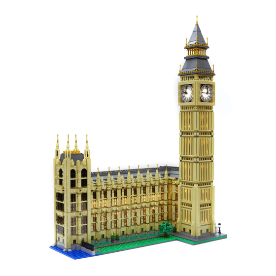
BIG BEN # 10253
Package contents:
6x Warm White Strip Lights
2x Green Strip Lights
17x Warm White 15cm Dot Lights
3x Warm White 30cm Dot Lights
2x 6-Port Expansion Boards
2x 8-Port Expansion Boards
5x 5cm Connecting Cables
4x 15cm Connecting Cables
1x 30cm Connecting Cable
1x 50cm Connecting Cable
16x Adhesive Squares
1x AA Battery Pack (requires 3x AA Batteries)
Plate Pieces
9x Plate 1x6, Black
6x Plate, Modified 1x2 with handle on End — C lose Ends, Black
6x Tile, Modified 1x1 with Clip, Black
2x Tile 1x1, Dark Grey
Note:
Place wires on the surface or under the LEGO building blocks.
The wire can be place between the building blocks or under the block, but they should be placed
between the studs correctly.
Insert the connectors to the ports.
Be careful when you are operating, there's only one correct way to insert, make sure the expansion
board is upward, find the soldered "=" sign on the left of the port. When you are inserting, the side
which the wires can be seen should be faced to the "=" sign and if you feel hard to insert, please stop,
and don't force it, for that may result in bent pins inside the port or overheating of the expansion board.
Advertisement

Summary of Contents for Brick Loot 10253
- Page 1 BIG BEN # 10253 Package contents: 6x Warm White Strip Lights 2x Green Strip Lights 17x Warm White 15cm Dot Lights 3x Warm White 30cm Dot Lights 2x 6-Port Expansion Boards 2x 8-Port Expansion Boards 5x 5cm Connecting Cables 4x 15cm Connecting Cables...
- Page 2 At this point, use the tweezers to straighten the bent pins. When installing dot lights, make sure they are correctly placed (Yellow LED package is exposed). You can put they either on the top of the studs or between studs. Connecting cable connectors to Strip Lights Take extra care when inserting connectors to ports on the Strip Lights.
- Page 3 Finally, please pay attention to the positive and negative terminals of the battery when installing the battery case. OK, Let’s Begin!
- Page 4 Instructions for installing this kit 1. ) We will first install lights to clock tower. To start, disconnect the the top part of the tower from where the bottom of the clock is.
- Page 5 Disconnect the 3 sections of the tower as per below: Remove clock border sections from all four sides of the tower and then remove the top section above the clock...
- Page 6 Carefully remove clock sections from all four sides of the tower as per below. Remove the light grey 2x6 technic plate from the centre.
- Page 7 2.) Take 2x White 15cm Dot Lights and then stick them to the following positions using 2x Adhesive Squares. Take another 2x White 15cm Dot Lights and then stick them to adhesive squares before bending the cable up in a 90 degree angle as per below.
- Page 8 Stick both Dot Lights to the following positions (directly over black studs): Take the top 2 Dot Light cables and then bring them together before looping the connector sides through the first hole of the light grey technic plate we removed earlier.
- Page 9 Repeat this step to install another 4x White 15cm Dot Lights to the opposite side of the tower. After threading the top two Dot Light cables through the whole of the technic plate, reconnect the plate in place ensuring cables underneath are in between studs. 3.) Turn to the next side along and then install another 4x White 15cm Dot Lights to the top and...
- Page 10 bottom corners in the below positions. (You will notice on these sides of the tower that there is only one plate to stick the top 2 lights on. Ensure you are sticking the Dot Lights to the exact same position as shown below).
- Page 11 Next, reconnect the clock section to the opposite side of the tower, ensuring you are keeping studs underneath free from cables. Turn to the next side and then carefully reconnect the clock section.
- Page 12 4.) Before we reconnect the remaining clock section, take the 50cm Connecting Cable and thread one side through the first hole from the top of the light grey technic plate. Pull the cable down all the way until you have about 10cm of cable slack between the top of the light grey plate and the connector before connecting it to a 6-Port Expansion Board.
- Page 13 Carefully disconnect the 1x6 tile from below and then thread the cable through one of the gaps. Pull the cable all the way down from underneath but ensure you still leave the 10cm of excess cable above. Reconnect the 1x6 tile ensuring the cable is neatly laid in between studs and then carefully reconnect the remaining clock section.
- Page 14 one larger cable. Take the section we removed from above and then thread all cables as well as the expansion board through the bottom of it before securely reconnecting on top of the clock section. Take 2x 5cm Connecting Cables and 2x 8-Port Expansion Boards and connect the the cables to end ports to join the expansion boards together.
- Page 15 Connect the other end of the 5cm cable to the 6-port expansion board on top of the clock and then connect all Dot Light Cables to available ports. Now take the time to test all the lights we have installed so far. Take the AA Battery Pack and insert 3x AA Batteries into it.
- Page 16 Once you have verified all is OK, disconnect the battery pack and then reconnect to the border sections to each side. 6.) We will now install lights to the top sections. Take the middle section and then disconnect pieces as per below.
- Page 17 Take a White 15cm Dot Light and then place it in the very centre of the base. Secure it in place by reconnecting the trans-clear pieces directly over the top. Reconnect remaining piece we removed earlier and then reconnect the roof.
- Page 18 NOTE: The side with the exposed cable will be facing toward the back. 7.) Take the section below and then turn over so we can access underneath of it.
- Page 19 Take the 2x Green Strip Lights and connect 2x 5cm Connecting Cables (one in between strip lights and another to the other side of a strip light). Use their adhesive backing to stick the green strip lights to the below positions underneath. Ensure the strip lights are stuck in the exact position as shown above otherwise we will not be able to reconnect this section.
- Page 20 Pull the Dot Light cable down just enough to be able to then connect it into the strip light with the spare port.
- Page 21 Tuck the expansion boards from the top of the tower in as much as possible and then take the roof section and connect the 5cm cable from the green strip light into the remaining port on the expansion board.
- Page 22 Reconnect roof on top of the clock section and ensure all is secure. You can now test what we have done so far by connecting the 50cm cable from the base of the clock to a spare expansion board and connect up the battery pack again. Verify all is working OK.
- Page 23 If all is OK, reconnect this whole section back to the rest of the tower and ensure you leave the 50cm cable outside the back. 9.) Turn Big Ben over to the back and remove the roof. You will require the LEGO removal tool to assist with this next step. Follow below images to get in between sections to allow us to remove a few 1x1 Bricks from the back.
- Page 24 After successfully removing bricks you can reconnect all sections back together, without the bricks we were required to remove.
- Page 26 10.) We will now install lights to the lamp posts at the bottom. First remove all three lamp posts and disconnect the tops. Take a White 30cm Dot Light and then place it directly over the lamp post piece. Secure it in place by reconnecting the top pieces directly over the Dot Light as shown below.
- Page 27 Repeat this step to install another 2x White 30cm Dot Lights to the remaining 2 lamp posts. 11.) Disconnect the following pieces from the bottom. Connect the first lamp post and then lay the cable in between studs before reconnecting one of the light grey tiles over the top of it to secure it in place.
- Page 28 Continue to lay the cable down and securing it place by reconnecting more tiles. Take a Black Plate 1x6 (which came in this light kit) and connect it to the following position. Take a Dark Bluish Grey Tile 1x1 and connect it to the next stud along.
- Page 29 Take the second lamp post and thread the connector side of it through the following space and then thread all along until it reaches the back. Pull it all the way through and then connect the lamp post on the black stud. Ensure the cable for the lamp post is pushed down and then reconnect the light grey tile over the top.
- Page 30 Take the cable from the first lamp post we connected and thread the cable through the last space and then out the back so that both cables are through. Connect the remaining lamp post and then push down the cable to allow us to reconnect the remaining light grey tile.
- Page 31 followed by the 3 Dot Light cables from the lamp posts. Thread the expansion board and cables through the spacing we created when we removed the bricks from the corner of the building. Take the 50cm cable from the tower and connect it to the expansion board we just threaded through.
- Page 32 We will not have enough cable length to allow us to easily do this so we will need to disconnect top sections of the wall. Follow the below images to remove sections to allow us to connect the cable to the expansion board.
- Page 33 Reconnect sections we removed earlier (trans black bricks in the corner). Hide the 50cm cable underneath tiles as shown below and then reconnect the roof.
- Page 34 13.) We will now install spot lights to light the outside of the building. Starting from the side where we already have a black 1x6 plate connected, locate the following LEGO pieces which came provided in this light kit and then assemble them together according to images below. Plate 1x6, Black ...
- Page 35 Take a White Strip Light and stick it to the base of the Lego plate using the adhesive backing. Since we will be installing a total of 6 Strip Lights to use as spotlights we will identify this particular one as striplight#1...
- Page 36 Locate the spare end of the 30cm connecting cable from the corner of the building and thread it through the spacing at the back of the building and then out through the second space behind the lamp posts. Connect this cable to the right port of striplight#1. Take a 15cm Connecting Cable and connect it to the left port of striplight#1 and then connect the base of the spot light to the black 1x6 plate.
- Page 37 Take another Plate, Modified 1x2 with handle on End — C lose Ends, Black and Tile, Modified 1x1 with Clip, Black and assemble them together to make another spot light.
- Page 38 Take another White Strip Light (striplight#2) and stick it onto another Black 1x6 Plate. Connect the other end of the 15cm connecting cable from striplight#1 the right port and then connect a new 15cm connecting cable to the left port. Connect the plate with striplight#2 to the spot light base. Locate LEGO pieces to assemble another 2 spotlight bases and then connect them to the following positions as per below.
- Page 39 Connect the 15cm connecting cable from striplight#2 to the right port of striplight#3 and then connect both plates to the spot light bases as per below. Assemble another few spot light pieces and connect them to the following position.
- Page 40 Take another White Strip Light (striplight#5) and stick it onto a 1x6 plate. Connect another 15cm connecting cable to the left port of striplight#5 and then connect the other end of the 15cm cable from striplight#4 to the right port. Connect the plate with striplight#5 onto the spot light base.
- Page 41 Turn over to the left side of the building and then connect a black 1x6 plate as well as spot light pieces to the following position. Take the last White Strip Light (striplight#6) and then stick onto the remaining 1x6 plate. Connect the other end of the 15cm cable from striplight#5 to the right port and then connect the plate with striplight#6 to the spotlight base.
- Page 42 14.) Take the AA Battery Pack and position against the back wall and connect the battery pack cable to the left port on striplight#6. Finally, turn on the battery pack and ensure all spot lights are working. Adjust the angles of the spotlights to ensure they are all shining evenly onto the building.
Need help?
Do you have a question about the 10253 and is the answer not in the manual?
Questions and answers