Table of Contents
Advertisement
Advertisement
Table of Contents

Summary of Contents for Aqua-Chem Cleaver-Brooks CB Series
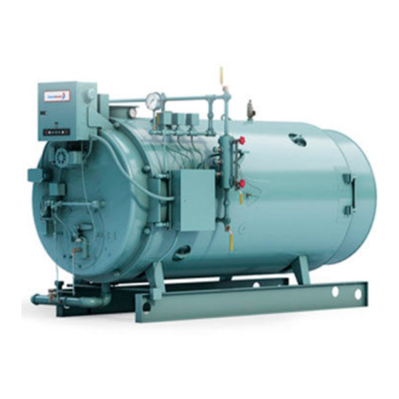
- Page 1 Compliments of Power Mechanical, Inc. Rental Boilers Used Boilers $25.00 U.S. CLEAVER-BROOKS MODEL CB, CB-LE PACKAGED BOILER Operation, Service, and Parts Manual 125 through 200 HP Fuel: Light Oil, Heavy Oil, Gas or Combination Manual Part No. 750-184 8/98...
- Page 2 SAFETY PRECAUTIONS AND Abbreviations ABBREVIATIONS Following is an explanation of the abbreviations, acronyms, and symbols used in this manual. Safety Precautions It is essential to read and understand the following safety Alternating Current precautions before attempting to operate the equipment. Failure to follow these precautions may result in damage to Automatic Reset equipment, serious personal injury, or death.
- Page 3 MODEL CB, CB-LE PACKAGED BOILER Operation, Service, and Parts Manual 125 through 200 HP Fuel: Light Oil, Heavy Oil Gas or Combination © Cleaver-Brooks 1998 Please direct purchase orders for replacement manuals to your local Cleaver-Brooks authorized representative NOTE: If you have a CB-HAWK ™ Boiler Management Control System, refer to CB-HAWK Installation, Operating and Service Manual No.
- Page 4 WARNING ! DANGER DO NOT OPERATE, SERVICE, OR REPAIR THIS EQUIPMENT UNLESS YOU FULLY UNDERSTAND ALL APPLICABLE SECTIONS OF THIS MANUAL. DO NOT ALLOW OTHERS TO OPERATE, SERVICE, OR REPAIR THIS EQUIPMENT UNLESS THEY FULLY UNDERSTAND ALL APPLICABLE SECTIONS OF THIS MANUAL. FAILURE TO FOLLOW ALL APPLICABLE WARNINGS AND INSTRUCTIONS MAY RESULT IN SEVERE PERSONAL INJURY OR DEATH.
-
Page 5: Table Of Contents
TABLE OF CONTENTS Chapter 1 Basics of Firetube Operation A. General ............... . 1-1 B. - Page 6 TABLE OF CONTENTS(continued) Chapter 4 Sequence Of Operation A. General ............... . 4-1 B.
- Page 7 TABLE OF CONTENTS (continued) Chapter 6 (continued) Adjustment Procedures V. Burner Drawer Adjustments ............6-18 W.
- Page 8 Chapter 9 Customer Service And Parts Front Door, Inner Door ............. . 3-5 Rear Head .
-
Page 9: Basics Of Firetube Operation
CHAPTER 1 Basics of Firetube Operation A. General ........1-1 B. -
Page 10: The Boiler
Chapter 1 Basics of Firetube Operation The general information in this manual applies directly to thereby reducing NOx emissions. In this approach, the Cleaver-Brooks Model CB Boilers in sizes ranging from 125 combustion air fan handles both the combustion air and the through 200 boiler horsepower for the following fuels: recirculated flue gases. -
Page 11: Construction
Basics of Firetube Operation Chapter 1 Steam boilers are designed for low pressure or high pressure Feedwater equipment should be checked and ready for use. Be sure that all valves, piping, boiler feed pumps, and applications. Low pressure boilers are limited to 15 psig receivers are installed in accordance with prevailing codes design, and are typically used for heating applications. - Page 12 Chapter 1 Basics of Firetube Operation OPERATING PRESSURE, HIGH LIMIT PRESSURE AND MODULATING STACK TEMPERTURE PRESSURE CONTROLS GAUGE CONTROL PANEL STEAM PRESSURE GAUGE VENT VALVE FORCED DRAFT FAN MOTOR NOZZLE HOLDER WATER COLUMN ATOMIZING AIR PRESSURE GAUGE WATER GLASS FLAME DRAIN VALVE DETECTOR OIL BURNER...
-
Page 13: Steam Controls (All Fuels)
Basics of Firetube Operation Chapter 1 D. STEAM CONTROLS (ALL FUELS) Operating Limit Pressure Control (Figure 1-3): Breaks a circuit to stop burner operation on a rise of boiler pressure at a selected setting. It is adjusted to stop or start the burner at a preselected pressure setting. - Page 14 Chapter 1 Basics of Firetube Operation 5. Water Column Assembly (Figure 1-6): Houses the low- VENT VALVE water cutoff and pump control and includes the water FLUE GAS OUTLET TEMP GAUGE gauge glass, gauge glass shutoff cocks. 6. Water Column Drain Valve (Figure 1-6): Provided so that the water column and its piping can be flushed regularly to assist in maintaining cross-connecting piping and in keeping the float bowl clean and free of sediment.
-
Page 15: Hot Water Controls (All Fuels)
Basics of Firetube Operation Chapter 1 11. Safety Valve(s) (Figure 1-9): Prevent buildup over the design pressure of the pressure vessel. The size, rating and number of valves on a boiler is determined by the ASME Boiler Code. The safety valves and the discharge piping are to be installed to conform to the ASME code requirements. - Page 16 Chapter 1 Basics of Firetube Operation burner firing rate when the manual-automatic switch is set on “automatic.” 5. Low-Water Cutoff (Figure 1-13): Breaks the circuit to stop burner operation if the water level in the boiler drops below safe operating point, activating low-water light and optional alarm bell if burner is so equipped.
- Page 17 Basics of Firetube Operation Chapter 1 movement. A set of springs allows the linkage to stay in a F. IFGR COMPONENTS (CB-LE) fixed position while the jackshaft rotates. 1. Flue Gas Transfer Port, IFGR Damper, and Flange Collar 4. Fuel Change-Over Linkage (Figure 1-16). When a boiler (Figure 1-15).
- Page 18 Chapter 1 Basics of Firetube Operation 6. Burner Drawer (Figure 1-15). The gas spudding pattern sound level and captures heat from the boiler and stack for the IFGR system may be different than that of a non- flue outlet. IFGR CB Burner of the same horsepower (HP) model Front Door Insulation (Figure 1-15).
-
Page 19: Burner Operation And Control
CHAPTER 2 Burner Operation and Control G. Controls For Combination Burners Only ..2-12 A. The Burner ....... 2-1 H. -
Page 20: The Burner
Chapter 2 Burner Operation and Control Air Inlet Figure: 2-4 Modulating Motor Figure: 2-5 Belt Driven Figure: 2-6 Frame Mounted Air Air Pump (CB) Pump (CB-LE or CB Option) Figure: 2-2 Air Intake Through Front Head Figure: 2-7 Forced Draft Fan Motor CB-LE Figure: 2-8 Forced Draft Fan Indicator lights signaling load demand, fuel valve, low water, and flame failure conditions are standard equipment. - Page 21 Burner Operation and Control Chapter 2 1, 2 3, 4, 7 N o t e : T h i s fi g u r e s h o w s f r o n t d o o r arrangement for a standard CB. 2-7 CB-LE) FORCED DRAFT FAN MOTOR FIGURE...
-
Page 22: Control And Component Function
Chapter 2 Burner Operation and Control B. CONTROL AND COMPONENT FUNCTION The term “control” covers the more important valves and components, including, but not limited to electrical controls or those monitored by the program relay. The operator must become familiar with the individual functioning of all controls before understanding boiler operation and procedures outlined in this manual. -
Page 23: Controls For Gas Firing
Burner Operation and Control Chapter 2 D. CONTROLS FOR GAS FIRING of combustion air. The fuel valves cannot be energized unless this switch is satisfied. The combustion air Depending upon the requirements of the insurance carrier or proving switch is provided on all gas fired or other governing agencies, the gas flow control system, or gas combination gas-oil burners. - Page 24 Chapter 2 Burner Operation and Control present in the pilot line when the pilot valves are closed. The valve closes when the pilot valves are energized. 3. Gas Pilot Shutoff Cock (Figure 2-11): For manually opening or closing the gas supply to gas pilot valve. 4.
- Page 25 Burner Operation and Control Chapter 2 MAIN GAS COCK BUTTERFLY GAS VALVE MAIN GAS VALVES MAIN GAS VENT VALVE GAS PRESSURE SENSOR Figure: 2-14 Gas Train (CB-HAWK) ROTARY AIR GAS FLOW DAMPER GAS TO SECONDARY AIR AIR FLOW BURNER TO BURNER OIL BURNER NOZZLE DIFFUSER GAS PILOT...
-
Page 26: Controls Common To Oil-Fired Boiler
Chapter 2 Burner Operation and Control E. CONTROLS COMMON TO OIL- Fuel Oil Controller (Figures 2-16 & 2-17): An assembly combining into a single unit the gauges, regulators and FIRED BOILERS (INCLUDING valves required for regulating the flow of fuel oil. All COMBINATION) controllers have the following integral parts. - Page 27 Burner Operation and Control Chapter 2 PACKING OIL METERING VALVE GLAND OIL MODULATING CAM OIL PRESSURE REGULATOR OIL BURNER PRESSURE GAUGE OIL SUPPLY OIL RETURN BACK PRESSURE ORIFICE TO MAIN OIL SOLENOID VALVE Figure: 2-17 Oil Control Valve Assembly - for Light Oil OIL MODULATING CAM OIL METERING VALVE PACKING GLAND...
- Page 28 Chapter 2 Burner Operation and Control 7. Terminal Block (Figure 2-16): The central connection C. Air Filter: The filter cleans the air supply prior to point for the supply and return oil. entering air pump. 8. Fuel Oil Strainer (Not Shown): Prevents foreign matter D.
-
Page 29: Additional Controls For Heavy Oil
Burner Operation and Control Chapter 2 F. ADDITIONAL CONTROLS FOR housed in the steam heater, but is housed separately on a hot water heater. Steam oil heaters on 15 psi boilers HEAVY OIL operate at boiler pressure. Steam oil heaters furnished on high pressure boilers are to be operated at less than 15 The oil heater (Figure 2-22 Steam) is provided to heat heavy psi. -
Page 30: Controls For Combination Burners Only
Chapter 2 Burner Operation and Control flow of steam to the steam heater to maintain temperature diminishing flame, which continues burning for of fuel oil. approximately 4 seconds after the oil solenoid valve closes. 12. Steam Pressure Gauge: Indicates steam pressure entering the heater. -
Page 31: Automatic Ignition
Burner Operation and Control Chapter 2 Insurance regulations may require two gas pilot solenoid valves with a normally open vent valve between them. The vent valve closes when the gas pilot valves open, and opens when the gas pilot valves shut to vent gas, should any be present in the pilot line during the deenergized period of the gas pilot valves. - Page 32 Chapter 2 Burner Operation and Control NOZZLE AIR PRESSURE GAUGE AIR STRAINER OIL BURNER NOZZLE MANIFOLD BLOCK SWING CHECK VALVE ATOMIZING AIR AIR PUMP OIL SOLENOID VALVE ATOMIZING AIR PRESSURE FEED BACK CONTROL TUBING ATOMIZING AIR PROVING SWITCH FUEL OIL CONTROLLER LUBE OIL STRAINER...
- Page 33 Burner Operation and Control Chapter 2 AIR STRAINER NOZZLE AIR PRESSURE GAUGE OIL BURNER NOZZLE MANIFOLD BLOCK SWING CHECK VALVE ATOMIZING AIR AIR PUMP ATOMIZING AIR PRESSURE FEEDBACK CONTROL TUBING OIL SOLENOID ATOMIZING AIR VALVE PROVING SWITCH FUEL OIL CONTROLLER LUBE OIL STRAINER OIL PRESSURE...
-
Page 34: Oil Fuel Flow - Heavy Oil
Chapter 2 Burner Operation and Control pressure is created by an orifice nozzle located in the oil Oil flow to the burner is controlled by the movement of the return line immediately downstream of the fuel oil controller. metering stem of the oil metering valve, which varies the flow to meet load demands. - Page 35 Burner Operation and Control Chapter 2 Figure: 2-27 Burner Drawer and Fuel Linkage Assemblies (CB-LE) The modulating motor (commonly called a damper motor) is control have any control over the damper motor, regardless of reversible. It has an internal limit switch that restricts shaft their setting.
- Page 36 Chapter 2 Burner Operation and Control Notes 2-18 750-184...
-
Page 37: Waterside Care And Requirements
CHAPTER 3 WATERSIDE CARE AND REQUIREMENTS A. General ........3-1 B. - Page 38 Chapter 3 WATERSIDE CARE AND REQUIREMENTS Note: If the operating water temperature If care is not taken to ensure adequate or proportional flow going to the system must be lower than through the boilers, wide variations in firing rates between the 1 7 0 °...
- Page 39 WATERSIDE CARE AND REQUIREMENTS Chapter 3 SYSTEM TEMPERATURE DROP - DEGREES ° F BOILER BOILER OUT- SIZE PUT (1000) (BHP) BTU/HR MAXIMUM CIRCULATING RATE - GPM 1,005 1,340 1,675 2,010 2,345 2,680 3,350 4,185 5,025 1,005 6,695 1,340 8,370 1,675 10,045 2,010 1,005...
- Page 40 Chapter 3 WATERSIDE CARE AND REQUIREMENTS TYPICAL LOW WATER CUT-OFF AND PUMP CONTROL A. NORMAL LEVEL OF WATER: FEED PUMP TURNS OFF AT THIS POINT. FILL PRESSURE VESSEL INITIALLY TO THIS HEIGHT. B. PUMP TURNS ON WHEN WATER LEVEL REACHES B. DISTANCE A-B IS APPROXIMATELY3/4 INCH.
-
Page 41: Water Treatment
WATERSIDE CARE AND REQUIREMENTS Chapter 3 2. STEAM BOILER Objectives of water treatment in general are: (1) Prevent hard scale deposits or soft sludge deposits, Feed Pump Operation which reduce heat transfer and can lead to overheated metal and costly downtime and repairs. BEFORE turning on the pump motor be certain that all valves in the water feed line are open to prevent possible damage to (2) Eliminate corrosive gases in the supply or boiler... -
Page 42: Boil-Out Of A New Unit
Chapter 3 WATERSIDE CARE AND REQUIREMENTS 2. PRESSURE VESSEL WARNING ! DANGER The waterside of the pressure vessel must be kept clean from grease, sludge, and foreign material. Such deposits, if present, Use of a suitable face mask, goggles, rubber will shorten the life of the pressure vessel, will interfere with gloves, and protective garments must be efficient operation and functioning of control of safety... -
Page 43: Washing Out
WATERSIDE CARE AND REQUIREMENTS Chapter 3 (5) All valves in the piping leading to or from the system must make-up water added, will require no further cleaning or be closed to prevent the cleaning solution from getting into treatment. However, since the system (new or old) can allow the system. - Page 44 Chapter 3 WATERSIDE CARE AND REQUIREMENTS Scale has a low heat transfer value and acts as an insulation Periodic adjustments are made to the valve setting to increase barrier. Scale retards heat transfer, which not only results in or decrease the amount of blowdown in accordance with the lower operating efficiency, and consequently higher fuel test analysis.
-
Page 45: Periodic Inspection
WATERSIDE CARE AND REQUIREMENTS Chapter 3 Most blow-off lines are provided with two valves, generally a damaging temperature differential that can cause harmful quick opening valve nearest the boiler and a slow opening stresses. Vessels should not normally be drained until all globe type valve downstream. - Page 46 Chapter 3 WATERSIDE CARE AND REQUIREMENTS method depending upon circumstances in the particular Damper and vents should be closed to prevent air from installation. reaching fireside surfaces. Periodic inspection should be made and absorption materials renewed. Whichever method is used, common sense dictates a periodic recheck of fireside and waterside conditions during lay-up to Wet storage is generally used for a boiler held in stand-by allow variations from the above methods for special area or...
-
Page 47: Sequence Of Operation
CHAPTER 4 SEQUENCE OF OPERATION A. General ........4-1 B. -
Page 48: Sequence Of Operation - Oil Or Gas
Chapter 4 SEQUENCE OF OPERATION High Fire Proving Circuit • Fuel valve interlock circuit • High fire switch (HFS) • Main gas valve auxiliary switch (MGVAS) • Oil valve auxiliary switch (OVAS) Running Interlock and Limit Circuit • Low oil pressure switch (LOPS) Blower Motor Starter Circuit •... -
Page 49: Flame Loss Sequence
SEQUENCE OF OPERATION Chapter 4 Note: The ignition trial cannot be started if valves are actuated by the motor through a linkage and cam flame or a flame simulating condition is assembly to provide modulated firing rates. sensed during the pre-purge period. A Note: Normal operation of the burner should safety shutdown will occur if flame is be with the switch in the manual-automatic... - Page 50 Chapter 4 SEQUENCE OF OPERATION technical bulletin should be referred to for assistance in pinpointing problems that may not be readily apparent. WARNING ! DANGER The program relay has the capability to self-diagnose and to The lockout switch must be manually reset display a code or message that indicates the failure condition.
- Page 51 SEQUENCE OF OPERATION Chapter 4 MNEMONIC DESCRIPTION MNEMONIC DESCRIPTION Burner Switch Amber (Color Of Pilot Light) Boiler Selector Switch AAFL Atomizing Air Failure Light BWPM Booster Water Pump Motor AAFR Atomizing Air Failure Relay Booster Water Thermostat AAPL Atomizing Air Proven Light AAPS Atomizing Air Proving Switch CAFL...
- Page 52 Chapter 4 SEQUENCE OF OPERATION MNEMONIC DESCRIPTION MNEMONIC DESCRIPTION FDJB Flame Detector Junction Box H/LWA High Low Water Alarm FDPS Flow Differential Pressure Switch High Limit Control Flame Failure Alarm HLFC High-Low Fire Control Flame Failure Light HLPC High Limit Pressure Control Flame Failure Relay HLTC High Limit Temperature Control...
- Page 53 SEQUENCE OF OPERATION Chapter 4 MNEMONIC DESCRIPTION MNEMONIC DESCRIPTION LLPR Low Limit Pressure Relay No Flow Relay Lead Lag Relay NGHPV Natural Gas Housing Purge Valve LLTC Low Limit Temperature Control LLTR Low Limit Temperature Relay Outlet Damper Actuator LOPL Low Oil Pressure Light Outlet Damper Motor LOPR...
- Page 54 Chapter 4 SEQUENCE OF OPERATION MNEMONIC DESCRIPTION MNEMONIC DESCRIPTION Power On Light STLWR Surge Tank Low Water Relay Pilot Oil Valve Pre-Purging Light (T.C.) Timed Closed Post Purge Relay (T.O.) Timed Open PPTD Post Purge Time Delay Terminal Block Program Relay Thermocouple Purge Ready Light Time Clock...
-
Page 55: Starting And Operating Instructions
CHAPTER 5 STARTING AND OPERATING INSTRUCTIONS A. General Preparation for Start-up - All Fuels ..5-1 B. Control Settings-Steam and Hot Water ... . 5-2 C. -
Page 56: Control Settings-Steam And Hot Water
Chapter 5 STARTING AND OPERATING INSTRUCTIONS For safety reasons, perform a final pre-startup inspection, Before operating the boiler feed pump or oil supply pump, be especially checking for any loose or incomplete piping or sure all valves in the line are open or properly positioned. wiring or any other situations that might present a hazard. -
Page 57: Gas Pilot
STARTING AND OPERATING INSTRUCTIONS Chapter 5 Note: The settings of all the above controls may require some readjustment after the boiler is started and running for a short period. The scale settings on the controls are relatively accurate, but are principally for use as guides. -
Page 58: Firing Preparations For No. 2 Oil (Series 100-200)
Chapter 5 STARTING AND OPERATING INSTRUCTIONS 20 detergent oil of a grade mentioned in Chapter 8 and fill in accordance with instructions given there. A I R I N T A K E STRAINER Check the oil level of the air intake strainer. When operating a standard CB boiler, make certain that the V-belt which drives the air pump is in place and has proper tension. - Page 59 STARTING AND OPERATING INSTRUCTIONS Chapter 5 If the oil supply tank is below the level of the oil pump, it is MANDATORY that the suction line to the pump be completely filled with oil prior to starting the pump to avoid the possibility of damage to the pump gears.
- Page 60 Chapter 5 STARTING AND OPERATING INSTRUCTIONS pressure to the adjustable spring pressure. Since the air pump is not running at this time, only tentative adjustment can be made. Without the air supply, adjust the fuel oil pressure regulator so that the oil burner gauge registers approximately 35 psi.
-
Page 61: Firing Preparations For Gas (Series 200-400-700)
STARTING AND OPERATING INSTRUCTIONS Chapter 5 Oil Temperature - After determining that the heater shell is at the point approximately 30°F lower than the normal filled and that fuel oil circulation exists, turn the oil heater burning temperature. If the system is equipped with a high oil switch to “on.”... -
Page 62: Start-Up, Operating And Shutdown - All Fuels
Chapter 5 STARTING AND OPERATING INSTRUCTIONS programmer to recycle normally for a new lighting trial. necessary to contact your local Cleaver-Brooks Several efforts may be necessary to “bleed” air from the line. authorized representative for assistance. After the IFGR system is initially set up, it will start up with WARNING ! DANGER the boiler as an integrated boiler system. - Page 63 Chapter 5 STARTING AND OPERATING INSTRUCTIONS BOILER HP PPM NOX "A" "B" "C" "D" "E" "F" "G" "H" "J" "K" 3/8" 3-1/8" 11° 79° 40° 20° 10° 13/16" 3-1/8" 11° 79° 40° 20° 10° 1" 5-3/4" 11° 79° 30° 23° 10°...
- Page 64 Chapter 5 STARTING AND OPERATING INSTRUCTIONS DOUBLE SPRINGS HOLE #1 (FAST OPENING DAMPER) HIGH-FIRE STOP SCREW LOW-FIRE STOP SCREW EXTERNAL ARM “B” HOLE #1 (SLOW -OPENING DAMPER) “A” EXTERNAL ARM INTERNAL ARM HOLE POSITION HOLE #5 (SLOW-OPENING DAMPER) HOLE # 8 (FAST OPENING DAMPER) 90∞...
- Page 65 STARTING AND OPERATING INSTRUCTIONS Chapter 5 On ignition failure, the flame failure light will glow and the Operating - Normal operation of the burner should be with blower will purge the boiler of unburned fuel vapors before the switch in the automatic position and under the direction of stopping.
-
Page 66: Control Operational Tests And Checks
Chapter 5 STARTING AND OPERATING INSTRUCTIONS increases. Observe the steam gauge to check the cut off pressure as the operating limit control shuts the burner down. WARNING ! DANGER Slowly open the header valve to release steam pressure and check the cut-in setting as the burner restarts. Check the It is advisable to check for tight shut-off of modulating control for the desired operating pressure range. -
Page 67: Adjustment Procedures
CHAPTER 6 Adjustment Procedures A. General........6-1 P. -
Page 68: Linkage - Modulating Motor & Air Damper
Chapter 6 Adjustment Procedures B. LINKAGE - MODULATING MOTOR The modulating motor must be able to complete its full travel range. AND AIR DAMPER The linkage consists of various arms, connecting rods, and ! DANGER CAUTION swivel ball joints that transmit motion from the modulating motor to the metering cam(s), to the rotary air damper, and to Do not restrict the full travel of the modulat- the gas butterfly valve, and the IFGR system used on the CB-... -
Page 69: Modulating Motor
Adjustment Procedures Chapter 6 Prior to initially firing a boiler it is advisable to check for free JACK SHAFT movement of the linkage. The damper motor must be allowed to complete its full stroke and the damper must move freely ROTARY AIR from low to high fire position. -
Page 70: Burner Operating Controls General
Chapter 6 Adjustment Procedures E. BURNER OPERATING CONTROLS Separate and independent controls affect modulated firing and burner on-off cycling. Figure 6-6 depicts a typical setting - GENERAL relationship of the Operating Limit Control, Modulating Contro l and the High Limit Control. Note: Adjustments to the boiler operating controls should be made by an authorized The burner will be “on”... - Page 71 Adjustment Procedures Chapter 6 100% Modulation Control Response Firing Rate Operating Limit Control Response High Limit Control Safety Shutdown Minimum Input (Low Fire) Falling Temp. or Pressure Modulated Firing “ON - OFF” Range Differential Rising Temp. or Pressure Burner Off (Burner OFF) (Burner OFF) (Burner ON)
-
Page 72: Modulating Pressure Controls (Steam)
Chapter 6 Adjustment Procedures ratios have been set, make the required adjustments to the controls to bring the boiler pressure or temperature up to meet the load requirements. To properly set the Modulating Control , carefully adjust it under load conditions, until the load is maintained with the burner firing at a steady rate. -
Page 73: Operating Limit Temperature Control (Hot Water)
Adjustment Procedures Chapter 6 maintained as shown in Figure 3-2, inspect the devices immediately and replace as required. M. COMBUSTION AIR PROVING SWITCH (CAPS) Air pressure against the diaphragm actuates the switch which, when made, completes a circuit to prove the presence of combustion air. -
Page 74: Gas Pilot Flame Adjustment
Chapter 6 Adjustment Procedures Note: On an initial starting attempt, portions The adjustment screw of the Atomizing Air Proving Switch of the fuel lines may be empty and require can then be adjusted until it breaks the circuit. Here, the “bleeding”... -
Page 75: Gas Pressure And Flow Information
Adjustment Procedures Chapter 6 9. If main flame has not been previously established, proceed to do so in accordance with instructions Pressure Required at Gas Train Entrance with Two Valves and 2 1/2” Pipe elsewhere in the manual. 10. The reading of the main flame signal should also be BOILER HP Standard checked. - Page 76 Chapter 6 Adjustment Procedures Conversely: To determine what the meter index reading should be in order REGULATOR INLET PRESSURE FACTOR to provide the volume of gas required for input, divide the PRESSURE (PSIG) desired flow rate by the proper pressure correction factor. 1.05 This answer indicates the number of cubic feet at line pressure which must pass through the meter to deliver the...
-
Page 77: Gas Fuel Combustion Adjustment
Adjustment Procedures Chapter 6 FIRST VISIBLE TRACE OF STACK HAZE PER CENT O IN FLUE GAS PER CENT CO 1/10 of 1% CO = 1,000 PPM PER CENT EXCESS AIR Figure: 6-9 Flue Gas Analysis Chart for Natural Gas Checking Gas Flow Q. - Page 78 Chapter 6 Adjustment Procedures CAUTION ! DANGER TO FOLLOWER OF GAS MODULATING CAM Turndown in excess of the burner design may damage the burner diffuser and/or the burner housing. Failure to follow these in- structions could result in damage to the equipment.
-
Page 79: Low-Gas Pressure Switch
Adjustment Procedures Chapter 6 It is generally recommended that O readings of between 3% Since the input of combustion air is ordinarily fixed at any to 4% be attained with less than 400 ppm CO, at high fire. given point in the modulating cycle, the flue gas reading is determined by varying the input of gas fuel at that setting. -
Page 80: High-Gas Pressure Switch
Chapter 6 Adjustment Procedures however, regulations require that the setting may not be greater than 150% of rated pressure. Manual resetting is necessary after a pressure rise. Press the reset lever after pressure falls. Be sure that the mercury switch equipped control is level. T. - Page 81 Adjustment Procedures Chapter 6 although your oil supplier will be able to give you more exact information based on an analysis of the oil. Review of the applicable maintenance instructions given in 3/16” 3/16” Chapter 8 will aid in maintaining an efficient fuel system. Note: To prevent oil heater coking, the fuel oil pump must be in operation during all 1/4”...
- Page 82 Chapter 6 Adjustment Procedures Standard CB Burner Housing (Rear View, Inside Front Head) CB-LE Burner Housing Front View Figure: 6-16 Burner Housing 6-16 750-184...
-
Page 83: Fuel Oil Combustion Adjustment
Adjustment Procedures Chapter 6 U. FUEL OIL COMBUSTION Take a flue gas analysis reading. If necessary, adjust the fuel oil controller to increase or decrease oil pressure. ADJUSTMENT Adjustments to the pressure should be done before attempting to adjust the screws in the metering cam. Ideally, the cam After operating for a sufficient period of time to assure a profile spring should be as close to the cam casting as warm boiler, adjustments should be made to obtain efficient... -
Page 84: Burner Drawer Adjustments
Chapter 6 Adjustment Procedures V. BURNER DRAWER ADJUSTMENT There are relatively few adjustments that can be made to the burner; however, a check should be made to assure that all components are properly located, and that all holding screws are properly tightened.The diffuser location on gas fired boilers is quite important. -
Page 85: Low-Oil-Pressure Switch
Adjustment Procedures Chapter 6 Z. LOW OIL PRESSURE SWITCH temperature exceeds the temperature of fuel oil entering the heater. The L.O.P.S. prevents burner ignition, or stops its operation, The electric oil heater on a hot water boiler burning No. 6 oil when the oil pressure is below the set point. - Page 86 Chapter 6 Adjustment Procedures Notes 6-20 750-184...
-
Page 87: Trouble Shooting
CHAPTER 7 TROUBLE SHOOTING Familiarity with the programmer and other controls in the system may be obtained by studying the contents of this WARNING ! DANGER manual. Knowledge of the system and its controls will make trouble shooting much easier. Costly down-time or delays can Trouble shooting should be performed only be prevented by systematic checks of actual operation against by personnel who are familiar with the... - Page 88 Chapter 7 TROUBLE SHOOTING Problem Solution BURNER DOES NOT No voltage at program relay power input terminals. START A. Main disconnect switch open. B. Blown control circuit fuse. C. Loose or broken electrical connection. Program relay safety switch requires resetting. Limit circuit not completed—no voltage at end of limit circuit program relay terminal.
- Page 89 TROUBLE SHOOTING Chapter 7 Problem Solution Running interlock circuit not completed. A. Combustion or atomizing air proving switches defective or not properly set. B. Motor starter interlock contact not closed. Flame detector defective, sight tube obstructed, or lens dirty. PILOT FLAME, BUT NO Insufficient pilot flame.
- Page 90 Chapter 7 TROUBLE SHOOTING If the programmer lockout switch has tripped: A. Check fuel lines and valves. B. Check flame detector. C. Check for open circuit in running interlock circuit. D. The flame failure light is energized by ignition failure, main flame failure, inadequate flame signal, or open control in the running interlock circuit.
-
Page 91: Inspection And Maintenance
CHAPTER 8 Inspection and Maintenance A. General ........8-1 N. -
Page 92: Fireside Cleaning
Chapter 8 Inspection and Maintenance check of all components of the boiler including piping, clean-out intervals since an accumulation of soot deposits valves, pumps, gaskets, refractory, etc. Comprehensive will raise the flue gas temperature. cleaning, spot painting or repainting, and the replacement of Tube cleaning is accomplished by opening the front and rear expendable items should be planned for and taken care of doors. -
Page 93: Water Gauge Glass
Inspection and Maintenance Chapter 8 D. WATER GAUGE GLASS A broken or discolored glass should be replaced at once. Periodic replacement should be a part of the maintenance program. Always use new gaskets when replacing a glass. Use a proper size rubber packing. Do not use loose packing, which could be forced below the glass and possibly plug the valve opening. -
Page 94: Flame Safety Control
Chapter 8 Inspection and Maintenance BLOWER MOTOR FUSE SIZING ELECTRICAL LOAD SINGLE PHASE 50/60 HERTZ THREE PHASE 50/60 HERTZ MOTOR HP 220-240 V 110-120 V 200-208 V 220-240 V 346-416 V 440-480 V 550-660 V 5-6/10 1-8/10 1-8/10 8/10 6-1/4 1-8/10 1-8/10 8/10... -
Page 95: Oil Burner Maintenance
Inspection and Maintenance Chapter 8 Turn the burner switch off. Reset the safety switch. Re- establish main fuel supply. WARNING ! DANGER When replacing a control, be sure to lock Checking Loss of Flame out the main power supply switch since the With the burner in normal operation, shut off the main burner control is “hot”... - Page 96 Chapter 8 Inspection and Maintenance Cleaning Oil Nozzle scratch or deform the orifices as well as the precision ground surfaces of the swirler and tip. Inspect for scratches or signs The design of the burner, together with the oil purge system of wear or erosion, which may make the nozzle unfit for on a heavy oil burner, make it unnecessary to clean the oil further use.
-
Page 97: Gas Burner Maintenance
Inspection and Maintenance Chapter 8 H. GAS BURNER MAINTENANCE J. SOLENOID VALVES The gas burner components should be inspected for evidence Foreign matter between the valve seat and seat disc can cause of damage due to improperly adjusted combustion. leakage. Valves are readily disassembled; however, care must Combustion adjustments should be checked monthly. -
Page 98: Forced Draft Fan
Chapter 8 Inspection and Maintenance conditions are found, the spring must be replaced STD. 30 PPM 20 PPM FGR RATE 60 PPM 25 PPM immediately to avoid the possibility of breakage in service. .010 .005 .040"± CLEARANCE .010 .050"± .060"± Use care to avoid damaging the cam or spring during .005 .000... -
Page 99: Cb-Le Fan/Motor Cassette Removal
Inspection and Maintenance Chapter 8 M. CB-LE FAN/MOTOR CASSETTE COMBUSTION AIR FLOW REMOVAL Before the boiler is commissioned at the job site, the IFGR FLUE GAS FLOW system should be visually inspected. The fan/motor cassette should be removed to expose the internal IFGR linkage and damper. -
Page 100: Cb-Le Inspection And Adjustment
Chapter 8 Inspection and Maintenance Figure 8-7: Fan/Motor Cassette N. CB-LE INSPECTION AND arm(s) and cycle the exterior linkage through its range of movement. ADJUSTMENT 2. The clearance between the impeller and backplate should NOx levels should be checked periodically to ensure be checked, and adjusted, if required. -
Page 101: Cb-Le Airbox Gasket Installation
Inspection and Maintenance Chapter 8 B. Adjust the retainers for the correct impeller clearance 5. Check and replace any gaskets that have been damaged. at two housing attachment points 180 ° apart. Gaskets that have been in use for one year or more should be replaced. -
Page 102: Cb-Le Fan/Motor Cassette Installation
Chapter 8 Inspection and Maintenance OVER-TRAVEL MECHANISM 30 ° SINGLE FUEL ARRANGEMENT AND 60 PPM SYSTEMS JACKSHAFT LINKAGE ROD QUICK-DISCONNECT LINKAGE 60 ° IFGR DAMPER CONTROL GAS JACKSHAFT DRIVE ARM OIL JACKSHAFT DRIVE ARM NOMINAL: ACTUAL POSITION VARIES WITH NOx REQUIREMENT JACKSHAFT PROXIMITY SWITCH JACKSHAFT ARM DUAL FUEL ARRANGEMENT... - Page 103 Inspection and Maintenance Chapter 8 JACKSHAFT LINKAGE ROD JACKSHAFT LINKAGE ROD POSITION LABEL QUICK DISCONNECT LINKAGE GAS JACKSHAFT DRIVE ARM OIL JACKSHAFT DRIVE ARM PROXIMITY SWITCH AND DRIVE ARM (COMBINATION GAS & OIL SYSTEMS ONLY) 2” 2-3/4” THE IFGR SYSTEM CAN BE EQUIPPED WITH EITHER JACKSHAFT LINKAGE ROD A SINGLE OR DUAL LINKAGE ARM, DEPENDING ON THE NUMBER OF FUELS USED AND THE NO...
- Page 104 Chapter 8 Inspection and Maintenance CBW ONLY TABLE ITEM 1 50 HZ OP CODE 60 HZ OP CODE BOILER H.P. 192-C-43 192-C-42 192-C-46 192-C-43 192-C-70 192-C-46 1/32" NOTES: 1. USE ITEMS #5 , 16 , & 17 AS REQUIRED TO OBTAIN CLEARANCE OF 1/32".
- Page 105 Inspection and Maintenance Chapter 8 ITEM DESCRIPTION PART NO. OP CODE USED ON SEE TABLE IMPELLER SEE TABLE 77-61 SPACER, IMPELLER 200HP @ 50HZ 77-A-184 SPACER, IMPELLER A4,A7 200HP @ 60HZ 77-61 SPACER, IMPELLER 200 H.P.@60 HZ. A4,A7 869-119 NUT, SELF LOCKING, JAM A4,A7 91-A-60 WASHER, SPACER...
- Page 106 Chapter 8 Inspection and Maintenance 2.798 .750 2.048 IMPELLER GROUP "A" .031 2.375 2.259 .750 1.500 IMPELLER GROUP "B" .250 1.793 2.50 .750 1.043 IMPELLER 16 18 GROUP "C" Figure 8-14: Blower Cartridge Assembly 8-16 750-184...
- Page 107 Inspection and Maintenance Chapter 8 BASIC BILL OF MATERIAL 60" DIA. - 125 THRU 200 ITEM PART NO. DESCRIPTION USED ON 2.358" (APPROX.) ADJUST TO AQUIRE TABLE BLOWER MOTER SPECIFIED IMP. TO IMP. HSG. GAP TABLE IMPELLER - OPEN TYPE .5 REF.
- Page 108 Chapter 8 Inspection and Maintenance “B” “D” LINKAGE CONNECTION POINT HOLE #1 HOLE #2 NOTE: RECORD “INSTALLED” “C” VALUES ON THIS ILLUSTRATION FOR FUTURE REFERENCE. A._____ FLANGE COLLAR SETTING FLANGE COLLAR B._____ DAMPER POSITION AT LOW-FIRE C._____ DAMPER LINKAGE ARE ANGLE (DEGREES) D._____ HOLE POSITION NUMBER “A”...
-
Page 109: Safety Valves
Inspection and Maintenance Chapter 8 Q. SAFETY VALVES Match-mark the cam hub and drive shaft. Match marking will enable replacement of the cam in its original The safety valve is a very important safety device and position and result in a minimum of cam adjustment deserves attention accordingly. -
Page 110: Air Pump And Lubricating System
Chapter 8 Inspection and Maintenance S. AIR PUMP AND LUBRICATING which is faced down. Be sure that the O-rings are properly located. SYSTEM 9. Using the stem as a guide, insert the assembled packing into the cavity, then withdraw the stem. Air Pump 10. - Page 111 Inspection and Maintenance Chapter 8 that it is fluffed out to fill all available space. Improper STEEL LUBE OIL FILLER HOLE WOOL OIL AIR TO BURNER packing can cause high oil consumption. After the last pad is SEPARATOR 5 OZ. SYSTEM EACH CHAMBER in place, slip the retainer screen onto the cylinder.
- Page 112 Chapter 8 Inspection and Maintenance Air Compressor Replacement OFFSET MISALIGNMENT Use the following procedures in replacing the pump on a CB- LE. Be sure to tag the motor leads if disconnected to simplify reconnection. Refer to Figure 22 for component locations. Dismantling ANGULAR Lift out the two front cylinder pins that hold the screen,...
-
Page 113: Head Inspection And Maintenance
Inspection and Maintenance Chapter 8 U. HEAD INSPECTION AND Loosen the clamp at the rear of the tank and remove the tank with copper tubing “A” attached. MAINTENANCE 10. Leave the rear pump bracket (coupling end) in place to aid in realignment of the replacement pump. Do this by WARNING ! DANGER removing the two capscrews that extend through the... -
Page 114: Refractory
Chapter 8 Inspection and Maintenance The opened head should be supported by blocking or jacking to eliminate possible deformation of the head or hinge area. Prior to closing, check all gaskets and sealing surfaces. If the door gasket is hard or brittle, it should be replaced. The fiberglass ropes should not be reused. - Page 115 Inspection and Maintenance Chapter 8 Note: The area between the dry oven and the board or equal, or a bed of refractory material, may be used throat tile requires a good seal. An improper to center the ring. or poor seal allows air leaks that can cause The liner tile can be fitted tightly against the furnace, since the overheating and burning of the dry oven.
-
Page 116: Sealing And Closing Inner Door And Front Head
Chapter 8 Inspection and Maintenance Sealing and Closing Inner Door and Scrape the old gasket material off the vessel to inner door sealing area and the dry oven to inner door sealing area. Front Head Using a wire brush clean off any excess gasket material or rust. - Page 117 Inspection and Maintenance Chapter 8 Inspect the condition of the blanket insulation on the inner Examine the condition of the burner housing and that all door. Replace the insulation if it’s found to be loose or torn. necessary burner setup is correct. Be sure the oil piping and Replace the gasket on the inner door and secure with new atomizing air piping are in good condition and not leaking, split clips.
- Page 118 Chapter 8 Inspection and Maintenance Swing the front head in place. A long punch or prybar might After all bolts are secured to XXXFoot Pounds, Tighten the be necessary to align the bolt holes. Insert bolts hand tighten. upper and lower hinge nuts evenly to pull the door securely After all bolts are threaded, continue tightening in a star against the vessel.
- Page 119 Inspection and Maintenance Chapter 8 Rear Door The rear door is a steel shell containing horizontal baffle and lined with insulation material and castable refractory (see Figure 8-38 & 8-39). Burned or discolored paint on the outer surface of the door does not necessarily indicate refractory trouble, but may be an indication of other conditions, such as: 1.
-
Page 120: Lubrication
Chapter 8 Inspection and Maintenance IFGR Lubrication V. LUBRICATION Motors should be lightly lubricated at startup, using the Electric Motors grease specified below or equivalent. Lubricate the motor as follows: Manufacturers of electric motors vary in their specifications for lubrication and care of motor bearings; their specific WARNING ! DANGER recommendations should be followed. -
Page 121: Oil Heaters-Electric, Steam, Hot Water
Inspection and Maintenance Chapter 8 W. OIL HEATERS - ELECTRIC, Table 8-2 CB-LE (IFGR) Maintenance STEAM, HOT WATER Daily • Check visually for free movement of IFGR linkage. An annual maintenance of the heaters consists primarily of removing the heating element from the shell and scraping any Quarterly •... - Page 122 Chapter 8 Inspection and Maintenance VISUAL INDICATOR GASKETS EXPANSION CHAMBER BOILER WATER CONNECTIONS OUTLET CAPILLARY SPACE BETWEEN TUBES INLET INNER TUBE RETURN CONNECTIONS OUTER TUBE Figure 8-39: Circuit Layout of Hot Water Oil Heater Windbox Temperature (Typical) - Natural Gas 60 PPM 130°-140°...
- Page 123 Inspection and Maintenance Chapter 8 SEMI- DAILY MONTHLY ANNUALY ANNUALLY • Check water level • Inspect burner • Clean low water cutoff • Clean fireside surfaces • Check combustion visually • Inspect for flue gas leak • Clean oil pump strainer, filter •...
- Page 124 Chapter 8 Inspection and Maintenance Notes 8-34 750-184...
- Page 125 CHAPTER 9 CUSTOMER SERVICE AND PARTS F U R N I S H C O M P L E T E I N F O R M AT I O N W H E N ORDERING PARTS - When ordering parts or spares, give the description and the quantity of parts desired, together with the complete nameplate data, including all electrical requirements.
- Page 126 Chapter 9 CUSTOMER SERVICE AND PARTS Table Of Contents Front Door, Inner Door ......3-5 Rear Head .
- Page 127 CUSTOMER SERVICE AND PARTS Chapter 9 REF. DWG. B REF. DWG. D REF. DWG. E CB PART # CB PART # DESCRIPTION RH DOOR LH DOOR 465-1330 INNER FRONT DOOR Insulated 465-1331 INNER FRONT DOOR Insulated 457-2868 INNER FRONT DOOR Plate Only 457-2869 INNER FRONT DOOR...
- Page 128 Chapter 9 CUSTOMER SERVICE AND PARTS NOTES: ITEM REQ. PART NO. DESCRIPTION BULK INSULATION, BLANKET, 1 1/2" THK. 2400°. 8# 872-500 1. ITEM #2 PINS TO BE SPACED ON 903-297 PIN, WELDING, #10 GA. X 4" LG. ST. STL 4" TO 5" MAX. CENTERS. 828-39 CLIP, WELDING ST.
- Page 129 CUSTOMER SERVICE AND PARTS Chapter 9 ITEM DESCRIPTION PART NO. SEE TABLE 872-688 INSULATION, INSWOOL, 1/4" THK SEE TABLE 919-51 ADHESIVE, SCOTCHGRIP 3M, #1300 903-297 PIN, WELDING, #10 GA. X 2-1/2" LG., ST. STL. 828-39 CLIP, WELDING, ST. STL. 150 OZ 872-443 RIGIDIZER, COATING CEMENT, CERA-PREG ** 65B804...
-
Page 130: Rear Head
Chapter 9 CUSTOMER SERVICE AND PARTS CB PART # WITH DAVIT DESCEIPTION 250 psi and up TO 200 psi 465-1537 REAR HEAD W/7” RELIEF DOOR 465-1987 465-153 REAR HEAD W/12” RELIEF DOOR 465-1988 465-1632 REAR HEAD W/O RELIEF DOOR 465-1986 Insulated Rear Head 750-184... - Page 131 CUSTOMER SERVICE AND PARTS Chapter 9 ITEM DESCRIPTION PART NO. USED ON 49-C-8 DRY OVEN 32-107 GASKET, DRY OVEN (SEE DWG 32-B-106) STUD, MACH., 1/2” - 13 X 2-1/8” LG. 841-513 (T- 5/8” #3 THD., N- 1-1/8” #2 THD.) 952-108 WASHER, STD., 1/2”...
- Page 132 Chapter 9 CUSTOMER SERVICE AND PARTS 120° SEE NOTE 6 60° CHALK MARKS FURNACE BRICKING TOOL FRONT HEAD PLATE TUBE SHEET FURNACE SEE NOTE 6. Furnace Liner & Bricking Model CB and CB-LE 750-184...
- Page 133 CUSTOMER SERVICE AND PARTS Chapter 9 CBW ONLY TABLE ITEM 1 BOILER H.P. 50 HZ OP CODE 60 HZ OP CODE 192-C-43 192-C-42 192-C-46 192-C-43 192-C-70 192-C-46 1/32" NOTES: 1. USE ITEMS #5 , 16 , & 17 AS REQUIRED TO OBTAIN CLEARANCE OF 1/32".
- Page 134 Chapter 9 CUSTOMER SERVICE AND PARTS ITEM DESCRIPTION PART NO. USED ON OP CODE SEE TABLE IMPELLER SEE TABLE 77-61 SPACER, IMPELLER 200HP @ 50HZ 77-A-184 SPACER, IMPELLER A4,A7 200HP @ 60HZ 77-61 SPACER, IMPELLER 200 H.P.@60 HZ. A4,A7 869-119 NUT, SELF LOCKING, JAM A4,A7 91-A-60...
- Page 135 CUSTOMER SERVICE AND PARTS Chapter 9 FRONT VIEW RIGHT SIDE VIEW DETAIL A-A FUEL OIL CONTROLLER DAMPER SEE NOTE 5 BUTTERFLY VALVE ON GAS TRAIN FRONT HEAD ASSEMBLY Front Head Linkage - Model CB 750-184 9-11...
- Page 136 Chapter 9 CUSTOMER SERVICE AND PARTS " 60 DIA. BOILER QUANTITY ITEM PART NO. DESCRIPTION WHERE USED OPTION 313-A-5 CAM ASSEMBLY BM,A4 295-99 GAS VALVE STEM ASSY. 85-A-1926 SUPPORT - JACKSHAFT BM,A4 67-A-17 ROD LINKAGE, GAS VALVE A4,A8 853-454 GASKET 476-00054 AIR DAMPER LINKAGE 476-00053...
- Page 137 CUSTOMER SERVICE AND PARTS Chapter 9 CB PART # 274-63 CB PART # 274-220 CB PART# 274-221 Jackshaft Retrofit Assembly Kits 750-184 9-13...
- Page 138 Chapter 9 CUSTOMER SERVICE AND PARTS CB PART # 476-53 Item REQ. Part # Description 67-16 Activation Rod 883-17 Ball Joint 10-288 Ball Joint Bushing 2-47 Modulation Motor Arm 869-21 Hex Nut, 1/4” - 20 869-22 Hex Nut, 3/8” - 24 860-39 Set Screw 868-138...
- Page 139 CUSTOMER SERVICE AND PARTS Chapter 9 CB PART # 476-54 Item REQ. Part # Description 67-109 Damper Linkage Rod 883-17 Ball Joint 10-288 Ball Joint Bushing 869-21 Hex Nut, 1/4” - 20 869-22 Hex Nut, 3/8” - 24 Not Used 860-39 Capscrew, 1/4”...
-
Page 140: Burner Drawer
Chapter 9 CUSTOMER SERVICE AND PARTS 24 15 46 19 17 33 18 17" 16-1/4” 9-1/4” 1/8” 7/16” 3/16” MAX. 3/32” MIN. 1" MIN. 1/4” 44 45 Burner Drawer-Gas Pilot Models 100-600, 125-200HP CB-LE 9-16 750-184... - Page 141 CUSTOMER SERVICE AND PARTS Chapter 9 ITEM PART NO. DESCRIPTION SEE TABLE NOZZLE-GUN ASSEMBLY 108-B-47 DAMPER 851-77 MICA, SHEET, PORT HOLE, #36 GA. X 1-1/2” DIA. 65-A-11 RETAINER SIGHT HOLE 860-176 MACHINE SCREW, RD. HD. 10-24 X 1/4” LG. 858-310 PLUG, PIPE, COUNTER SUNK, 3/4”...
-
Page 142: Burner Housing
Chapter 9 CUSTOMER SERVICE AND PARTS TUBE SHEET BAFFLE SEAL BAFFLE (FRONT EXTENSION) STUD INNER DOOR 1/2" NOTES: BAFFLE ATTACHMENT 1. SEAL BAFFLE AT TUBE SHEET AND SHELL WITH ITEM #12. 2. PAINT WITH SYNCRON #5112 ZINCOAT PER INSTRUCTIONS ON DRAWING #876-A-73 AFTER CUTTING THREADS. - Page 143 CUSTOMER SERVICE AND PARTS Chapter 9 ITEM PART NO. DESCRIPTION USED ON 869-30 NUT, HEX, 3/8"-16 952-93 WASHER, 3/8" 32-A-605 GASKET, BURNER DRAWER TO HOUSING SEE TABLE BURNER DRAWER 32-A-603 GASKET, BURNER HOUSING TO FRT. HEAD 900-79 BULK PIPE, 3" X 13-1/2" LG. TBE. NAT.
- Page 144 Chapter 9 CUSTOMER SERVICE AND PARTS CONTROL CABINET (HAWK) ITEM PART NO. DESCRIPTION USED ON OPTION 283-B-2978 CONTROL CABINET SEE TABLE 1 SWITCH BRACKET 881-231 PILOT LIGHT 881-232 LENS, RED 118-644 NAMEPLATE, LOW WATER 836-620 SWITCH, OPERATOR 836-623 SWITCH CONTACT BLOCK 118-1382 NAMEPLATE, BURNER OFF-ON 836-746...
- Page 145 CUSTOMER SERVICE AND PARTS Chapter 9 CONTROL CABINET (NON-HAWK) ITEM PART NO. DESCRIPTION USED ON OPTION 119-405 CONTROL CABINET (W/SUB BASE) PROGRAMMER-BASE TABLE 1 - ITEM 8 PROGRAMMER-DISPLAY VOLTAGE PROGRAMMER-CHASSIS SEE TABLE 3 TABLE BM HP 200-208V 220-240V 346-416V 440-480V 575-600V PROGRAMMER-AMPLIFIER PROGRAMMER-MODULE 833-1884...
- Page 146 Chapter 9 CUSTOMER SERVICE AND PARTS BILL OF MATERIAL FOR ENT. BOX ITEM PART NO. DESCRIPTION USED ON OPTION 434-61 TERMINAL STRIP, 25 TERMS 118-1865 PLATE, I.D. FOR TERM. STRIP 884-78 GROUND LUG 848-223 FUSE BLOCK, CONTROL CIRCUIT 118-297 NAMEPLATE, DECAL CONTROL CIRCUIT 832-347 FUSE, FRN-15 848-1083...
- Page 147 CUSTOMER SERVICE AND PARTS Chapter 9 BLOWER MOTOR FUSE SIZING ELECTRICAL LOAD SINGLE PHASE 50/60 HERTZ THREE PHASE 50/60 HERTZ MOTOR HP 110-120 V 220-240 V 200-208 V 220-240 V 346-416 V 440-480 V 550-660 V 5-6/10 1-8/10 1-8/10 8/10 6-1/4 8/10 1-8/10...
-
Page 148: Front Head Electrical
Chapter 9 CUSTOMER SERVICE AND PARTS NOTES 1. FOR NON-HAWK, ITEMS 5, 13 THRU 21, & 23 ARE STOCKED AS 506-478 FOR STD., FM, KEM, & IRM INSURANCE. 506-479 FOR IRI, F & I. INSURANCE. 2. FOR NON-HAWK, ITEMS 22, 24 THRU 29, 33, & 34 ARE STOCKED AS 309-56. 3. - Page 149 CUSTOMER SERVICE AND PARTS Chapter 9 ITEM DESCRIPTION PART NO. USED ON 817-436 CAPS 817-1742 SCANNER 848-101 BUSHING, ANTI-SHORT 952-92 LOCKWASHER, 1/4" 868-137 CAPSCREW, HEX HD, 1/4-20 X 1" LG. 832-118 IGNITION TRANSFORMER OIL ONLY 60 HZ 832-107 IGNITION TRANSFORMER GAS &...
- Page 150 Chapter 9 CUSTOMER SERVICE AND PARTS NOTES: 1. ALL DIMENSIONS ARE APPROX. 2. UNLESS OTHERWISE NOTED, ALL PIPE TO BE 3/4" SCH. 40 ASTM A120 WELDED BLACK STL. AND ALL FITTINGS 150# M.I.. 3. USE ITEM 27 WITH 836-72 HOTS. 4.
- Page 151 CUSTOMER SERVICE AND PARTS Chapter 9 ITEM PART NO. DESCRIPTION USED ON OPTION 838-C-81 TANK - HEATER 3 & 5 kw U.S. 838-C-35 TANK - HEATER 3 & 5 kw CAN. 7-1/2 kw 195-B-238 TANK - HEATER ELEMENT - HEATER QQ/QU 7-A-52 U-BOLT...
- Page 152 Chapter 9 CUSTOMER SERVICE AND PARTS NOTES: 1. UNLESS OTHERWISE NOTED, ALL OIL PIPE TO BE SCH. 40 ASTM A120 WELDED BLACK STL. AND ALL FITTINGS TO BE 150# M.I.. 2. SWIVEL JOINTS SHOULD BE LINED UP EVEN WITH FLANGE RING. 3.
- Page 153 CUSTOMER SERVICE AND PARTS Chapter 9 ITEM DESCRIPTION PART NO. USED ON OPTION 652-B-9 HEATER TANK 125-150 H.P. 652-B-10 HEATER TANK 200 H.P. 8-A-650 BRACKETS OIL HEATER 8-A-65 BRACKET-OIL LINE 845-313 ELBOW 1/2" ODC. X 1/2" NPT. 847-1715 BARCO JOINTS 940-2116 RELIEF VALVE 843-252...
-
Page 154: Electric Oil Heater
Chapter 9 CUSTOMER SERVICE AND PARTS OIL HEATER RATINGS (KW) SHIPPED LOOSE (NOT SHOWN) (ALL BOILERS) #4 OIL #5 & #6 OIL PART NO. DESCRIPTION USED ON OPTION HORSEPOWER STEAM HOT WATER SEE TABLE OIL PUMP PRESSURE 16-300 833-1902 STARTER 50-200 923-47 STRAINER... - Page 155 CUSTOMER SERVICE AND PARTS Chapter 9 ITEM PART NO. DESCRIPTION USED ON 530-B-94 SUPPORT PANEL & AIR HOOD ASSEMBLY 530-B-384 SUPPORT PANEL & AIR HOOD ASSEMBLY 200 @ 50 HZ 333-A-17 STRAINER ASSEMBLY 923-79 AIR CLEANER 538-A-136 AIR - OIL TANK ASSEMBLY 538-A-134 AIR - OIL TANK ASSEMBLY 8-C-2324...
- Page 156 Chapter 9 CUSTOMER SERVICE AND PARTS ITEM DESCRIPTION PART NO. USED ON 868-159 CAPSCREW, HEX HD, 3/8"-16 X 1-3/4" LG. 868-176 CAPSCREW, HEX HD, 1/2"-13 X 2" LG. 952-93 LOCKWASHER, 3/8" 952-94 LOCKWASHER, 1/2" 869-15 NUT, HEX, 1/2"-13 77-28 SPACER 841-566 SCREW, SHEET METAL, #10 X 5/8"...
- Page 157 CUSTOMER SERVICE AND PARTS Chapter 9 BOLT HEAD ON TOP SIDE ELEVATION BILL OF MATERIAL FOR 60" DIA. ITEM PART NO. DESCRIPTION USED ON 505-113 COMPRESSOR ASSEMBLY 8-A-2345 BRACKET 868-104 CAPSCREW, HEX. HD. 5/16"-18 X 1" LG. 952-114 LOCKWASHER, 5/16" 952-133 WASHER, 5/16"...
-
Page 158: Air Compressor /Air Line Piping
Chapter 9 CUSTOMER SERVICE AND PARTS ITEM PART NO. DESCRIPTION 827-8 BULK CONDUIT, 1/2" THINWALL EMT. X "B" LG. APPROX. 827-8 BULK CONDUIT, 1/2" THINWALL EMT. X "A" LG. APPROX. 8-A-2833 BRACKET 928-33 PIPE STRAP, 1/2" CONDUIT 868-136 CAPSREW, HEX HD. 1/4"-20 X 3/4" LG. 859-118 ELBOW, STREET, 1/2"... -
Page 159: Light Oil/Air Piping-Front Head
CUSTOMER SERVICE AND PARTS Chapter 9 FUEL OIL CONTROLLER " " DETAIL A-A HAWK REQUIRMENT(SEE NOTE 1) " " FRONT HEAD DETAIL C-C TOP VIEW TO PILOT TO BURNER 38 39 FRONT HEAD SIDE VIEW FRONT VIEW Light Oil/Air Piping-Front Head 750-184 9-35... - Page 160 Chapter 9 CUSTOMER SERVICE AND PARTS Stem Packing Kit - 880-370 ITEM PART NO. DESCRIPTION USED ON OPTION Control Valve Rebuild Kit - CB125,150, Light Oil & Heavy Oil - 880-75 24-84 VALVE STEM (24-B-81) Heavy Oil - 880-76 VALVE STEM (24-B-81) 24-85 CB 200 739-D-73...
- Page 161 CUSTOMER SERVICE AND PARTS Chapter 9 CB-125 CB-150 CB-200 ITEM CB Part # Description 850-109 Pressure Gauge, 0-20 PSI. 0-35”WC 507-1348 Gas Pilot Tube 817-1935 High Gas Pressure Switch 5-35”WC 817-774 Low Gas Pressure Switch 3-21”WC 948-197 Solenoid Valve, 1/2” NPT 948-54 Vent Valve, 1-1/4”...
- Page 162 Chapter 9 CUSTOMER SERVICE AND PARTS CB-125 CB-150 CB-200 ITEM CB Part # Description 850-109 Pressure Gauge, 0-20 PSI. 0-35”WC 507-1348 Gas Pilot Tube 817-1935 High Gas Pressure Switch 5-35”WC 817-774 Low Gas Pressure Switch 3-21”WC 948-197 Solenoid Valve, 1/2” NPT 825-30 Gas Cock, 1/2”...
-
Page 163: Pressure Controls
CUSTOMER SERVICE AND PARTS Chapter 9 NIPPLE NOT REQUIRED ON 15# STANDARD 4-3/4" 3/4" X 3/4" X 1/4" TYP. (3) PLACES 150 - 250 16 - 150 BILL OF MATERIAL PART NO. PART NO. PART NO. PART NO. ITEM QTY PART NO. DESCRIPTION USED ON 817-111... - Page 164 Chapter 9 CUSTOMER SERVICE AND PARTS REAR FLANGE CB70/CB100/E100 CB70/CB100/E100 CB70/CB100/E100 240-280 DEG F. HTHW 281-360 DEG F. HTHW 30-125 HW ITEM 8-995 8-995 8-967 8-995 8-995 8-995 817-1249 817-1249 817-1244 817-699 817-699 817-399 817-1281 817-1257 817-1050 817-1028 817-1028 817-378 817-698 817-700 817-400...
- Page 165 CUSTOMER SERVICE AND PARTS Chapter 9 BILL OF MATERIAL OPTION ITEM PART NO. DESCRIPTION WHERE USED 60" BRACKET (8B937) TEMPERATURE CONTROL (MC) WELL SEPARABLE TEMPERATURE CONTROL (HLC) WELL SEPARABLE TEMPERATURE CONTROL (OLC) MACH. SCR. #10-32 x 3/4" BUSHING RED 3/4" x 1/2" NUT MACH.
-
Page 166: Water Column
Chapter 9 CUSTOMER SERVICE AND PARTS CUT ITEM 24 TO SUIT HW ONLY SEE DETAIL CUT PROBE TO SUIT L.W.C.O. CASTING MARK " " L.W.C.O. HW ONLY A.L.W.C.O. M D. M. " " DETAIL A - A L.W.C.O. M D. M. 1"... - Page 167 CUSTOMER SERVICE AND PARTS Chapter 9 EXTERNAL A.L.W.C.O. USED ON 817-98 CONTROL, AUX. L.W.C.O. (AUTO RESET) INTERNAL A.L.W.C.O. CONTROL, AUX. L.W.C.O. (MANUAL RESET) 150# 1 817-97 M D. M. USED ON (ABOVE 15# ONLY) CONTROL, AUX. L.W.C.O. (MANUAL RESET) 200-250# 817-306 CONTROL, AUX.
- Page 168 Chapter 9 CUSTOMER SERVICE AND PARTS Notes 9-44 750-184...
- Page 169 NOTES...
- Page 170 Performance Proven Worldwide e-mail: info@cleaver-brooks.com Web Address: http://www.cleaver-brooks.com...
Need help?
Do you have a question about the Cleaver-Brooks CB Series and is the answer not in the manual?
Questions and answers