Advertisement
Quick Links
Quick Installation Guide
Quick Installation Guide
Version 1.2
September 2020
HELZEL Messtechnik GmbH
Carl-Benz-Strasse 9
24568 Kaltenkirchen, Germany
www.helzel.com
e-mail: wera@helzel.com
Tel.: +49 (0) 4191 - 95 20 – 0
Fax: + 49 (0) 4191 - 95 20 – 40
Document
WERA4-Quick-US-200917
Page 1 of 73
Advertisement

Related Manuals for HELZEL Messtechnik WERA

Summary of Contents for HELZEL Messtechnik WERA
- Page 1 Quick Installation Guide Quick Installation Guide Version 1.2 September 2020 HELZEL Messtechnik GmbH Carl-Benz-Strasse 9 24568 Kaltenkirchen, Germany www.helzel.com e-mail: wera@helzel.com Tel.: +49 (0) 4191 - 95 20 – 0 Fax: + 49 (0) 4191 - 95 20 – 40...
- Page 2 The WERA system is designed for radar measurements at the ocean coast line. The transmitter antennae array will transmit a continuous RF signal with a power less than 10 Watts per antenna. Even if this low power won’t generate any harmful voltage or radiation, it is required to take care that the installation of the transmit antenna system complies with the FCC requirements.
- Page 3 Please note this document is an extract of the complete user manual. The chapter and figure numbers are used from this manual, for this reason some chapter and figure numbers are missing is this quick guide. The WERA manual and other related documents can be found on the WERA PC at: /home/wera/Documents/...
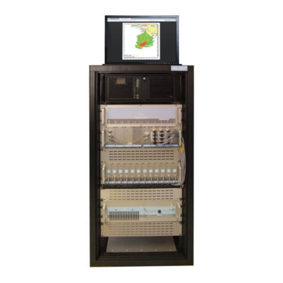
- Page 4 1.5 – STM 1.6 – ADC 1.7 – ADU 2.0 – REceiver Rack 2.1 – REC 1 to 12 3.0 – Power Amplifier 3.1 – Manual Gain Control Figure 1: Front view, WERA 12-Channel System Document WERA4-Quick-US-200917 Page 4 of 73...
- Page 5 2.2 – RER control input 2.3 – Cal input 2.4 – LoD input 2.5 – Antenna input 1 .. 12 2.6 – AC input Figure 3.2: Back view, WERA RER (12 channels) – Version with internal Filters (RIN6) Document WERA4-Quick-US-200917 Page 5 of 73...
- Page 6 2.4 – 20 V output 2.5 – Antenna input 1 .. 12 2.6 – AC input Figure 3.3: Back view, WERA RER (12 channels) – Version with external Filters (on AIP) WERA-FCR FrequencyControlRack Figure 4: FCR Block Diagram The frequency control rack generates all required rf signals (clock and sweep) and provide the Tx and Lo signals.
- Page 7 1.1.2 – Trigger signal out, to be connected to STM Figure 5: Clock Module Master clock for the whole WERA system The standard module has got one clock and trigger output only. The third connector is for the SYNC antenna only (option).
- Page 8 Normally their output is a linearly swept frequency sweep. In the newer WERA versions (since 2009) just the Rx sweep is active during acquisition. The Tx is used for calibration only and can be used as a “spare part” in case of a failure of the Rx sweep.
- Page 9 Quick Installation Guide A/D converter - ADC 1.6.4 – Analog signal in, N+3 1.6.3 – Analog signal in, N+2 1.6.2 – Analog signal in, N+1 1.6.1 – Analog signal in, N 1.6.5 – LED indicates sampling Figure 8: ADC Module Each ADC module samples I and Q information of four receive channels.
- Page 10 WERA-CTU - WERA Control-Unit The WERA control unit is programmed via an I C Bus driven from the DIO 72. This unit programs the sweep modules with the parameters received from the real time unit and controls the receive and transmit signals.
- Page 11 The RSC 230 module is used to remotely switch on and off individual parts of the WERA system, e.g. to save power at sites that produce their own energy.
- Page 12 Quick Installation Guide WERA-RER - Receiver Rack (12 channels) – external filter 4.10.1 Figure 12: RER Block Diagram for 12 channels (external filter) The receiver rack holds the input filters and receiver modules of up to 12 channels. For this version the Receiver Input Filters (RIN filters, chapter 4.11) and the Calibration Splitter Unit (Cal-Splitter, chapter 4.12) are mounted on the Antenna Interface Plate (AIP).
- Page 13 Quick Installation Guide 4.10.3 WERA-RER - Receiver Rack (8 channels) +9 ±1dBm Figure 14: RER Block Diagram for 8 channels The receiver rack holds the input filters and receiver modules of up to 8 channels. For a system with 16 receive channel you always need two receiver racks, each containing 8 receiver.
- Page 14 The system will operate even with burned fuses but with reduced signal levels at these channels. If a different operating frequency is needed, the RIN modules have to be exchanged. In older WERA versions the lid of the RER unit need to be removed to get access to the SMA connectors. 4.11.3...
- Page 15 Quick Installation Guide 4.11.4 Dual-Receive-Input-Filter - DRIN (for 8 channels) Each RIN module contains band-pass input filters for four receive channels as well as the relays for the internal calibration and switching filters. Each of the two filters per channel is designed for a specific frequency and bandwidth to provide optimum noise reduction.
- Page 16 Quick Installation Guide 4.13 Receiver - REC 2.1.1 – trimmer for i/q phase -> fine-adjustment 2.1.2 – Analog signal out to ADC Figure 19: Receiver Module The receiver modules receive the antenna signal over the receiver input filters, mix it down in frequency and amplify it for the ADC modules.
- Page 17 Quick Installation Guide 4.14 WERA-PA - Power Amplifier (Rack Version) The standard version of the power amplifier is housed in 19” rack, 3 HU, see figure 21. This version can provide up to 80 Watts output power to compensate cable loss. The antennas should be connected via an external 1:4 power splitter with two pairs of “phase...
- Page 18 Figure 22: Power Amplifier – Rack Version – rear view with 4 outputs 4.15 WERA-IPC - User-Interface-PC The User Interface PC is used to control the WERA system. Measured data are stored on (removable) hard disks and can also be send to a central processing station over a data link.
- Page 19 Block Diagrams and Table of Interconnecting Cable Description Cable Id Quant. Connect to Connect to PA Control (15 poles male-female) 1511 1.21 AC Power of the whole WERA System Line 1511 1 (2) 3.7/8 Status control RER 1653 AC power cable 1 m for FCR...
- Page 20 Quick Installation Guide Figure 24: Block Diagram WERA IV 12 Channel with AIP (external Filters) Part 1 of 2 Document WERA4-Quick-US-200917 Page 20 of 73...
- Page 21 Quick Installation Guide Figure 25: Block Diagram WERA IV 12 Channel with AIP (external Filters) Part 2 of 2 Document WERA4-Quick-US-200917 Page 21 of 73...
- Page 22 Quick Installation Guide Figure 26: Block Diagram WERA IV 8 or 12 Channel with RIN or RIN6 (internal Filters) Part 1 of 2 Document WERA4-Quick-US-200917 Page 22 of 73...
- Page 23 Quick Installation Guide Figure 27: Block Diagram WERA IV 8 or12 Channel with RIN or RIN6 (internal Filters) Part 2 of 2 Document WERA4-Quick-US-200917 Page 23 of 73...
- Page 24 Quick Installation Guide Note: All the delivered cables have identification numbers. Plug in all the cable (given in table 1) fig. 9 and refer to fig. 1 to 8 Take care for the correct order of connection of cable 9026 for REC and ADC. The REC`s are numbered from left to right, the ADC inputs are numbered from bottom to top and left to right, for example: 1.6.4 –...
- Page 25 "foots" underneath the lowest rack. For this reason please use only the recommended order for setting up the rack: o PC WERA Interface PC o FCR Frequency Control Rack o RER...
- Page 26 Quick Installation Guide 1.0 – WERA Interface PC 2.0 – FCR 3.0 – RER 4.0 – Blind plate for ventilation 5.0 – Power Amplifier 5.0 – Room for UPS (depends on rack) Figure 30: WERA front view Please note: Exact rack mounting order is required for optimal cooling...
- Page 27 So a data link and software between the PC and ups is required. In case of a very insecure power line, it might be better to operate the WERA system from a UPS that continuously is generating the AC. Please contact factory to get more information about these options.
- Page 28 3 men Connect line power and phone connection Unpack system components and install rack 2 men Power up system and configure WERA Control 1 men Run internal calibration (256 samples, 80 Hz offset) 1 men Connect Calibration Box outdoors at end of Rx cables 1 men and run calibration.
- Page 29 Quick Installation Guide Position of Container If possible find a place for the container in-line or behind the antenna arrays. It is possible to use the roof of the container to place the TX array. In this case the container should be placed in line or in front of the Rx array.
- Page 30 Quick Installation Guide Tx Antennas The optimum position of the Tx antenna array is in a distance of 5 to 10 Lambda from the Rx array orientated in-line with the Rx array. But there are other options as well, see below: Optimum with Rx and Tx in-line Curved array to provide more angular field of view...
- Page 31 Quick Installation Guide The Tx array geometry defines the Tx beam pattern. The rectangular configuration with 0.5 Lambda along the water front and 0.15 Lambda perpendicular provides a theoretical null towards the Rx array and a quite narrow beam towards the bore sight of the radar. At the outer edges (±...
- Page 32 If this distance is very long, the RF power loss on the coax cable can be quite high. The cable loss depends on the distance, frequency and cable type. Please refer to the “WERA Tables” to check if for your installation this cable loss can be accepted.
- Page 33 The “mirror” pole would suppress the signal from the other side of the array. A lot of other antenna construction versions are available, please contact the Wera team. Wooden beam mounted to metal anchor...
- Page 34 Quick Installation Guide Antenna Tuning 5.6.1 Rx-Antenna Tuning The antenna tuning coils should be installed with contact grease and secured by means of the hose clamps. Please attach just loose for the first step, since the depth of shifting in the tuning coil into the pole will be used for fine tuning later on.
- Page 35 Quick Installation Guide The antennas should be tuned to the intended working frequency and it needs to be matched to 50 , low VSWR over a wide bandwidth > 500 kHz. Please note, always use a cable of at least ¼ wave length to connect the antenna meter. Layout this test cable almost identical to the proposed layout for the final connection, otherwise the readings will be incorrect.
- Page 36 Unpack the system carefully, keeping the boxes undamaged. These may be used again if the installation should be moved in the future. Please ensure that the WERA racks are mounted in the right order. Connect all cables at the front and rear of the system.
- Page 37 If the system is connected correctly, the user interface PC is directly connected to the UPS and can be started without switching on the WERA system. Turn on the PC and wait until Linux has booted. Please check if there is access to WERA Desk.
- Page 38 (Attention, never use the output from the Power Amplifier for the calibration). This cable need to be connected to the centre connection of the “Calibration Box”. Start a Calibration under the WERA Control Centre. Use settings for a short run: 256 samples, 0.260 sec sweep time, 80 Hz offset Check the results using “Plott_WERA_Cal_lsq...
- Page 39 PA to lowest gain (turn knob to left most position or use “PA” setup section of “WERA Remote control” software if remote controlled PA). Start a Calibration under the WERA Control Centre. Use settings for a short run: 256 samples, 0.260 sec sweep time, 80 Hz offset Check the results using “Plott_WERA_Cal_lsq...
- Page 40 Quick Installation Guide If one voltage is higher, check if the PA is really operating with lowest gain. If the power need to be further reduced, connect a 20 dB N-attenuator (enclosed in the tool box) at the input of the PA and run the test again. Now the voltage must be smaller than 7 volts but maybe now it is lower than 1 volts.
- Page 41 Use the identical WERA settings as before at the beginning of this chapter. Start a Calibration under the WERA Control Centre. Use settings for a short run: 256 samples, 0.260 sec sweep time, 80 Hz offset Check the results using “Plott_WERA_Cal_lsq according to the description in pos.
- Page 42 Quick Installation Guide 5.15 Adjust Power Amplifier (PA) level (Tune Up Info Part I) There are two power amplifier versions available. The outdoor version in a water proof box and a rack mount version. The rack mount version is easy to handle because all displays and knobs are at the front panel.
- Page 43 If the Rx levels are already at 7 Volts even if the Tx level is still quite low (no green power LED on, just the yellow one left of the green) please proceed with: Switch the Receiver Attenuation on WERA Desk (chapter 7.1.5) to 4 dB and increase the PA gain by 3 dB Attention: Always check that at the PA no red LED is on.
- Page 44 Please refer to the following chapters to get instructions about how to run these tests. Final configuration The system configuration file should be pre-configured prior to the installation. If modifications are required, please refer to the WERA user manual, chapter 6: “Final Configurations”. Document...
- Page 45 The WeraDesk web page can be used to control the system, perform measurements or configure repetitive automatic measurement cycles. Note that the real status of the system can only be observed from the WERA-Desk Status window. The status window can be opened over the link “Open Status Window”.
- Page 46 To dynamically update the 'Maximum Range' and 'Data Acquisition Time' fields, Javascript needs to be enabled for the browser. Do not enter values into these two fields. If you allow JavaScript to open unrequested windows, a window showing the current WERA status will automatically pop up. (Allow pop-ups for your browser) Clicking 'Open Status Window' opens the status window manually.
- Page 47 If available, the input signals of each channel can be attenuated by a fixed value in dB. Some WERA systems got 0 dB and –6 dB receiver input attenuation available, while the latest systems got steps of 0 dB, -4 dB, -8 dB and –12 dB receiver input attenuation.
- Page 48 Zero (DC). This mode is especially useful for cross calibrations (one WERA transmitting, the other WERA receiving), or during ship calibration. Note that for newer WERA systems only one sweep module (RX) is used to generate LO- and TX-signals, if the RX-Offset value is set to zero. Only for calibration measurements with a frequency offset between LO- and TX-signal, both sweep modules are programmed.
- Page 49 By setting multiple WERAs to a different Cont. Acqu. Start Time, they can be operate in different time slots to avoid one WERA to interfere with another WERA. To set up a timing scheme, also take a look at Cycle Repetition Time and Data Acquisition Time.
- Page 50 “process after Measurement” check box is activated. Note that in the wera crontab the DPT and a frequency scan are initiated within the same minute, but the start of the scan is delayed by approx. 30 seconds, while the DPT starts immediately.
- Page 51 Quick Installation Guide 7.1.14 Bandwidth Reduction This parameter is used in continuous mode only, when pre-scan and frequency adapt is activated. This value needs to be smaller or equal to the bandwidth determined by the range cell depth parameter. If the frequency pre-scan post-processing software cannot find a free gap for the desired sweep bandwidth, then the sweep bandwidth will automatically be reduced step by step, until a useful free gap in the frequency band is found, or until the defined value for this parameter is reached.
- Page 52 „Optimum operating frequency“. 7.1.19 Range Offset This parameter is used to correct the absolute range measured by the WERA by the offset introduced by cable delays. Both Rx and Tx cable lengths must be taken into account.
- Page 53 The Number of Range Cells should not be set to values larger than the working range physically possible by WERA due to the attenuation of the ground wave. This value should be monitored and readjusted after having installed the system.
- Page 54 Quick Installation Guide 7.1.23 Data Acquisition Time The value of this field is calculated by multiplying the Samples per Data Run with the Chirp Length. Can’t be modified. 7.1.24 RX Offset This is an optional frequency offset between TX- and LO-signal. It is normally only used for calibration measurements to enable the test signal to pass the receivers high pass filters.
- Page 55 In this case the Bragg lines in the range Doppler maps will not be vertically anymore. WERA-Desk Status window The Status Page reflects the actual status of the WERA system and is automatically updated every 5 seconds (You need JavaScript for the update to work). Document...
- Page 56 On each WERA UPC the results of regularly processed measurement can be viewed via web. These pages can be accessed via the start page of WERA Control Center. To display the start page on the UPC, enter the URL http://localhost/~wera/ .
- Page 57 Quick Installation Guide With a click on the desired directory the contained status overview web page will be opened. Each status overview displays some information about the last measurement, followed by plots of radial sea surface current, radial sea surface current power level, radial current noise level, radial current signal to noise level and a plot of external frequency usage over time from the last frequency scan.
- Page 58 If the latest WERA remote control software is running and configured to regularly measure the voltages and temperatures of the WERA racks, then it will generate a web page with plots of these parameters over time. This information can be useful to monitor the status of the electronics power supplies, fans and the air conditioning in the building.
- Page 59 DPT signal might not be able to travel the shortest route to all antennas and this will change the phases. WERA DPT (Direct Path Test) time series overview (optional) ith the DPT time series of measurements it is possible to retrieve information about antenna behaviour.
- Page 60 For manual installation instructions see chapters 6.7 Create direct path test setup and 6.8 Set up your individual wera crontab. WERA DPT (Direct Path Test) spectra overview (optional) If the automatic DPT test measurement has been activated, then additionally to the comparison plots and time series from chapter 7.5 and 7.6 plots of the last spectra for...
- Page 61 This can be done via internet remote access or sitting in front of the WERA system on-site. It’s used as an graphical user interface giving the operator a fast overview of system performance and service/maintenance information.
- Page 62 The software can either be operated sitting in front of the WERA system on-site, or remotely by logging in to the graphical user interface via internet remote access. Software like NX NoMachine, TeamViewer, OpenVPN or similar may be used for this purpose.
- Page 63 In addition you can see the maximum temperature, that is allowed inside the racks (FCR and RER). If one temperature is going above this limit, the WERA-system will automatically be switched off and will not automatically be switched back on again, before the temperature in all these racks has fallen at least 5 °C below the limit.
- Page 64 Note that WERA II RER contain up to 8 receiver modules, while WERA IV RER contain up to 12 receive channels. The software is currently configured to support up to 16 receive channels. So if a WERA IV RER is available, it is assumed that there is only one RER.
- Page 65 “save and close” to close the setup window. If you want to discard your changes, then click on “close setup”. 7.10.1.3 WERA Setup-Window – PA (Power Amplifier) tab This section of the setup window can optionally be used to control a newer version rack mounted power amplifier and check its status.
- Page 66 “save and close” to close the setup window. If you want to discard your changes, then click on “close setup”. 7.10.1.4 WERA Setup-Window – Low Power tab In the Low Power section of the setup window it is possible to activate the Low Power Options by selecting the corresponding check box.
- Page 67 The test is verifying a valid internet-connection by pinging up to two ip addresses like “www.yahoo.com” and “www.google.com”. If from both addresses no response is received after several tries, the selected relays are switched to the opposite setting from the WERA System power tab for a short time, then switched back. Document...
- Page 68 Make sure that no hardware is connected to the selected ports, which should not be switched off. Further note that the PSR in the WERA IV FCR or later do not have got the optional “Digital Out” and “Aux2” outputs.
- Page 69 WERA warning system will handle messages in the default directory only. For each site a unique site name should be used to be able to identify, which WERA station send out the message. It is recommended to use the same site name for all parts of the warning system.
- Page 70 Quick Installation Guide 7.10.1.7 WERA Setup-Window – Email tab The Email section of the setup window is not activated. In the future this section could be used to configure warning emails, which may automatically be send out if an error has been detected.
- Page 71 Data processing scripts These scripts are used to carry out specific software tasks after each measurement. Please refer to the WERA user manual chapter 8 if some settings might need to be modified. Data formats There are various data formats used after each processing step. Please refer to the WERA user manual to get details about the formats.
- Page 72 WERA Server Manual for all visualization and data management options. All WERA data processing programs are command – line tools. So a base knowledge of UNIX/Linux shell use is very advantageously. Please refer to the WERA user manual for details.
- Page 73 Tx centre position LON: LAT: Container position LON: LAT: Height of antenna foot Radial type (a) Calibration, Internal /home/wera/etc/calibration.wera_internal___________ (b) Cable calibration /home/wera/etc/calibration.wera_cable_____________ (c) Optional Ant. Cal. /home/wera/etc/calibration.wera_ant_______________ (d) other methods /home/wera/etc/calibration.wera_xxx_______________ Calibration activated: file name: (a) (b) (c) (d) Sign: calibration.wera...
Need help?
Do you have a question about the WERA and is the answer not in the manual?
Questions and answers