Table of Contents
Advertisement
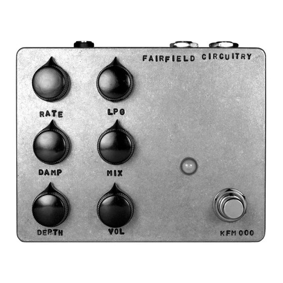
SHALLOW WATER
K-Field Modulator
ABSTRACT
Shallow Water's essence could be
characterized as uncertain, subtle
and nostalgic.
Practically, this describes an
effect built around your typical
analogue chorus/vibrato circuit
wherein the signal is delayed by
a few dozen milliseconds using
a bucket brigade device. Another
signal then modulates this delay
time to create changes in pitch,
called vibrato. Chorus is achieved
by mixing the original signal with
the delayed signal, creating the
moving comb filters that tickle
our ears and feather our bangs.
Still, major differences can be
noticed when studying the k-field
modulator's architecture. The most
striking are how the delay time
is modulated in a random fashion
and how the recovery filter moves
in relation to the input signal.
Both these differences place
Shallow Water in a category of its
own, appropriately called k-field
modulators.
As the present gets lost, the
future becomes the past.
PSEUDO RANDOM GENERATOR
The random quality of the modulation begins in a simple pro-
gram residing on a microcontroller. Its output resembles steps
of random voltages, seperated by random time intervals. The
RATE control effectively sets the overall range of these time
intervals.
INTEGRATOR AND DEPTH
These random stepped voltages are processed through a filter/
integrator, giving control over the slope at which the steps
will reach their new values. As DAMP is increased, the random
steps become slow and sluggish, instead of sharp and abrubt.
DEPTH defines the amount of modulation that will be used to
modulate the time delay of our input signal. There is a strong
interaction between all three controls affecting modulation; that
is, RATE, DAMP and DEPTH.
ENVELOPE FOLLOWER AND RECOVERY FILTER
Once the input signal has passed through the delay line, a
recovery filter and some kind of gate is necessary to remove
unwanted noise generated by the bucket brigade device. To
achieve this, the input's envelope is followed and used to mod-
ulate the frequency of a low pass filter. The amount of envelope
is set by the LPG control, yielding bouncy, lo-fi responses to
quick and snappy gate-like behaviours.
IN
ENVELOPE
LPF
FOLLOWER
ANTI-ALIASING
FILTER
VOLTAGE
DELAY
CONTROLLED
LOW PASS
LINE
FILTER
DEPTH
VOLTAGE
CONTROLLED
CLOCK
DRIVER
OUT
DAMP
RATE
NOISE FILTER
PSEUDO
+
RANDOM
INTEGRATOR
GENERATOR
PHYSICALS
- 1/4" mono input/output jacks
- 2.1mm DC connector
- 4.7" x 3.8" enclosure dimensions
TECHNICALS
- true bypass
- input impedance
1MΩ
- output impedance
2kΩ
- power supply
9 to 9.6 VDC
- current draw
40 mA max.
NOTES ON POWERING
Shallow Water was designed to operate using
your typical centre negative, regulated 9-9.6
VDC power supply. The pedal is protected
against reversed polarity and overvoltage
conditions. Always check your power supply
for proper voltage and polarity before con-
necting. There is no battery connection inside
the pedal.
EXTENDED WARRANTY
Fairfield Circuitry will repair or replace any
malfunctioning product for a period of 2
years after purchase date. Problems resulting
from modifications or misuse may cancel this
warranty. The owner will cover all shipping
expenses. This warranty applies only to origi-
nal owner of the product. Proof of purchase
might be required.
In short, the best thing to do is to contact us
as soon as possible with a description of the
symptoms, even if the warranty is expired.
Advertisement
Table of Contents

Subscribe to Our Youtube Channel
Summary of Contents for Fairfield Circuitry Shallow Water
- Page 1 ENVELOPE FOLLOWER AND RECOVERY FILTER time to create changes in pitch, Shallow Water was designed to operate using called vibrato. Chorus is achieved your typical centre negative, regulated 9-9.6 Once the input signal has passed through the delay line, a by mixing the original signal with VDC power supply.
- Page 2 CONTROLS MORE CONTROL INSIDE output envelope amount input RATE 9 VDC BOOST AND PAD The RATE control adjusts the time There are 2 jumpers at the input stage to match F A I R F I E L D C I R C U I T R Y rate of intervals at which the random pitch your input signal’s level and impedance.
Need help?
Do you have a question about the Shallow Water and is the answer not in the manual?
Questions and answers