Advertisement
Quick Links
Advertisement

Summary of Contents for ROOF MAKER SLIMLINE LANTERN
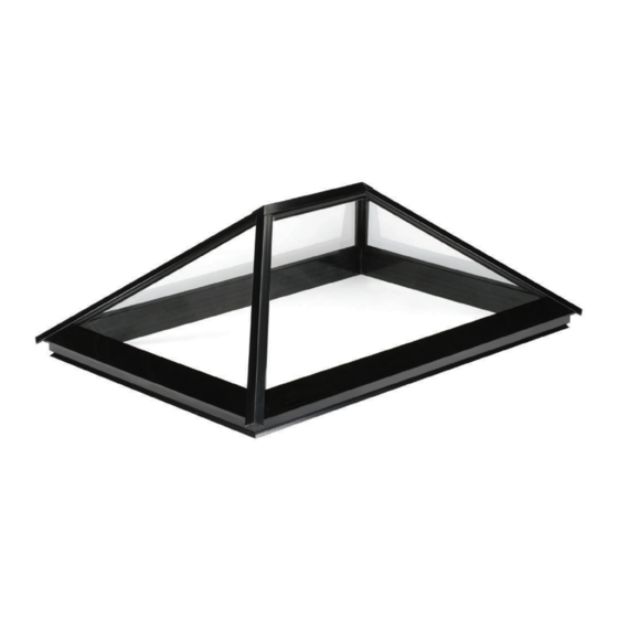
- Page 1 PRODUCT SPECIFCATION & INSTALLATION GUIDE FULLY ASSEMBLED SLIMLINE ® LANTERN...
- Page 2 Call us: 0116 269 6297 DOUBLE GLAZED SLIMLINE ® LANTERN Mon-Fri 9-5pm STANDARD PRODUCT SPECIFICATION 4mm Reflex+ toughened safety easy clean outer pane 16mm Argon gas filled cavity Spacer bar system= warm edge no metalic, tri-seal/super spacer desiccant impregnated 4mm Reflex+ toughened safety high-spec low E inner panel Structurally bonded silicone Plastic packer...
- Page 3 Call us: 0116 269 6297 TRIPLE GLAZED SLIMLINE ® LANTERN Mon-Fri 9-5pm STANDARD PRODUCT SPECIFICATION 4mm Reflex+ toughened safety easy clean outer pane 4mm Reflex+ toughened safety high-spec low E centre panel Spacer bar system= warm edge no metalic, 4mm Reflex+ toughened safety high-spec low E tri-seal/super spacer desiccant impregnated inner panel Structurally bonded silicone...
- Page 4 Call us: 0116 269 6297 Mon-Fri 9-5pm FULLY ASSEMBLED SLIMLINE ® LANTERN: INSTALLATION GUIDE INTRODUCTION TO THE GUIDE ON DELIVERY, YOU WILL RECEIVE; Please adhere to the relevant Health and Safety guidelines when moving heavy objects and working at This guide covers the installation of a Slimline ® roof lantern, •...
- Page 5 Call us: 0116 269 6297 Mon-Fri 9-5pm STEP 1: STEP 2: PREPARE THE TIMBER KERB PREPARE THE ROOF MEMBRANE Before you begin the installation of your new roof lantern, you will have installed the We recommend that you apply your roof membrane after installing your roof lantern, timber kerb.
- Page 6 Call us: 0116 269 6297 Mon-Fri 9-5pm STEP 3: STEP 4: SCREW FIX THE LANTERN TO THE TIMBER KERB APPLY SILICONE TO THE TOP SURFACE OF THE TIMBER KERB Apply a thick bead of silicone all the way around the timber kerb about 20mm from the You now need to secure the upstand to the timber kerb by inserting screws into the purpose made groove that runs around the bottom of the frame externally, about internal edge.
- Page 7 Call us: 0116 269 6297 Mon-Fri 9-5pm STEP 5.1: STEP 5.2: FLASHING GUIDELINES (Sheet membrane) FLASHING GUIDELINES (GRP membrane) Ensure the roof membrane is tucked right under the dedicated drip lip that sits just If using GRP to finish the roof, you should silicone bond a 4mm plywood border around under the glass.
- Page 8 Call us: 0116 269 6297 Mon-Fri 9-5pm ROOF SECTION FITTING GUIDE Level timber upstand required When no blind is selected, distance between plaster stop bead and glass to be approx 10mm and must not be in contact with glass IF INCLUDING BLACKOUT BLINDS Black out blind option When blinds are selected, plaster up to blind trim...
- Page 9 Call us: 0116 269 6297 Mon-Fri 9-5pm Multiple Rocker switch wiring diagram – 3 Core - Single Rocker switch wiring diagram – 3 Core - ROCKER SWITCH CONTROLLED OPENING VENT - WIRING GUIDE (3 CORE CABLE) motors motor The diagram below illustrates how you need to wire in your opening vent to your switch, giving examples for both a single vent or when 2 vents have been included. Please note - We provide a white plastic rocker switch when you have opted for a rocker switch controlled rooflight.
- Page 10 Call us: 0116 269 6297 Mon-Fri 9-5pm ROCKER SWITCH CONTROLLED OPENING VENT - WIRING GUIDE (5 CORE CABLE) The diagram below illustrates how you need to wire in your opening vent to your switch, giving examples for both a single vent or when 2 vents have been included. Please note - We provide a white plastic rocker switch when you have opted for a rocker switch controlled rooflight.
- Page 11 Ventec 100 Series Call us: 0116 269 6297 Thermostatic and Rain Controller Mon-Fri 9-5pm Ventec100 Series Advanced Operations Guide Ventec100 Series Advanced Operations Guide The default settings of our 100 series controller are suited to most user applications. However, if The default settings of our 100 series controller are suited to most user applications.
-
Page 12: Frequently Asked Questions
100 Series Installation Guide Frequently Asked Questions We have compiled the following list of Frequently Asked Questions to assist you FREqUENTLY ASKED qUESTIONS fig. fig. fig. with any troubles you may encounter. Max 5amp Insert the tip of a Fused Spur screwdriver into these sockets to Q. - Page 13 Call us: 0116 269 6297 Mon-Fri 9-5pm CABLE LOCATION GUIDE SLIMLINE ® ROOF LANTERNS WITH ELECTRONIC VENTS AND BLACKOUT BLINDS INTRODUCTION AND TOOLS REQUIRED When you have opted for a Slimline ® roof lantern with electronic vent/s and a blackout blind, the electrician will need to drill through the lantern’s built in upstand profile in order to run the vent motor cable through it.
- Page 14 Call us: 0116 269 6297 Mon-Fri 9-5pm CABLE LOCATION GUIDE SLIMLINE ® ROOF LANTERNS WITH ELECTRONIC VENTS AND BLACKOUT BLINDS PREPARATION GUIDE FOR FULLY ASSEMBLED LANTERNS When you have received a fully assembled Slimline ® roof lantern, the upstand section will already house the blackout blind. The blind will be fully open and you will see that it sits along the width of the unit, at the side that it would retract to.
- Page 15 Call us: 0116 269 6297 Mon-Fri 9-5pm CABLE LOCATION GUIDE SLIMLINE ® ROOF LANTERNS WITH ELECTRONIC VENTS AND BLACKOUT BLINDS STEP 2 In the same area, measure down from the top edge of the profile by 15mm and where the two marks meet, use your 10mm drill bit to drill a hole.
- Page 16 Call us: 0116 269 6297 Mon-Fri 9-5pm CABLE LOCATION GUIDE SLIMLINE ® ROOF LANTERNS WITH ELECTRONIC VENTS AND BLACKOUT BLINDS STEP 3 STEP 4 You now need to drill a 10mm hole through the bottom of the upstand, Place the rubber grommets into vertically level with the first hole you made on the inside face, through both holes you have just drilled.
- Page 17 Call us: 0116 269 6297 Mon-Fri 9-5pm CABLE LOCATION GUIDE SLIMLINE ® ROOF LANTERNS WITH ELECTRONIC VENTS AND BLACKOUT BLINDS STEP 5 STEP 6 Now the lantern is installed, you can create the groove/s required in the timber You can now run the cable that comes from the vent actuator through the hole reveals, to house the vent actuator cabling.
Need help?
Do you have a question about the SLIMLINE LANTERN and is the answer not in the manual?
Questions and answers