
Summary of Contents for FaderMate Master Control Unit
- Page 1 Product Fitting Guide v1.0.0 (October 2018) © 2018 FaderMate. All rights reserved.
-
Page 2: Table Of Contents
Table of Contents 1 Introduction............................3 1.1 Background..........................3 1.2 Document Outline........................3 1.3 Further Reading........................3 2 System Overview..........................4 2.1 Component Descriptions......................4 2.2 MCU Overview........................4 2.3 MCU Kit Contents........................5 2.4 FCU Overview........................5 2.5 FCU Kit Contents........................6 2.6 Block Diagram........................7 3 Console Compatibility Requirements.....................8 3.1 Fader Body Fit........................8 3.2 Fader Cables...........................9 3.3 FCU Fit..........................10... -
Page 3: Introduction
Each bank of 8 faders is controlled by a single FCU circuit board (see section 2.4) which must be installed in the fader tray void. The FaderMate system as a whole is controlled by a 1U rackmount Master Control Unit (MCU - see section 2.2). -
Page 4: System Overview
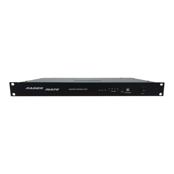
4 Fader Control Unit (FCU) kits. 2.2 MCU Overview The Master Control Unit is the heart of the FaderMate system. It is a 1U rackmount module which should be mounted close to the console. It connects the FaderMate system to the computer by means of 8 MIDI DIN connectors (on the rear panel) and a USB management connector (on the front panel). -
Page 5: Mcu Kit Contents
2.3 MCU Kit Contents The MCU kit contains the following components: a) 1 x FaderMate MCU module b) 1 x daisychain data interface cable c) 1 x master data interface cable d) 1 x length of two core power cable... -
Page 6: Fcu Kit Contents
2.5 FCU Kit Contents The FCU kit contains the following components: • 1 x FaderMate FCU module • 8 x Alps motorised faders (fitted with custom ribbon cables) • 8 x metallised fader knobs A full FCU kit is shown in Figure 2.5.1. -
Page 7: Block Diagram
2.6 Block Diagram The block diagram of an example 24 channel FaderMate installation is shown in Figure 2.6.1. Figure 2.6.1 – 24 Channel Installation Block Diagram A single MCU can support between 1 and 4 (inclusive) FCUs and thus up to 32 moving faders can be accommodated. -
Page 8: Console Compatibility Requirements
3 Console Compatibility Requirements Although FaderMate is intended to be a universal system, there are several mechanical factors to consider when determining whether your console is compatible with the system. These requirements can be summarised as: The motorised faders must fit in place of the original faders ... -
Page 9: Fader Cables
FaderMate will only fit a console which can accommodate this extended fader body. The parts which are most likely to foul the motorised fader are • The first potentiometer/switch in the channel strip (at the top of the fader) •... -
Page 10: Fcu Fit
3.3 FCU Fit An outline (plan view) drawing of the FCU circuit board is shown in Figure 3.3.1. Note that if the diagram is printed on A4 paper it is to scale. Crucially, the FCU board has dimensions of 23.2 cm x 14.5 cm x 2.5cm (width x length x height) and would usually be placed in the fader tray directly underneath the faders which it controls. - Page 11 Figure 3.3.1 – FCU Circuit Board Dimensions...
- Page 12 MCU through a single set of connectors/cables, they are only necessary for systems which include more than 1 FCU. Figure 3.3.2 – FCU Boards With FaderMate System Connections The standard motorised fader (including connector) adds a further 3.5cm to the required fader tray depth giving a total required height of 6 cm from the bottom of the fader faceplates to the bottom of the fader tray.
- Page 13 Figure 3.3.3 – FCU Circuit Board and Motorised Fader Installed in Console Figure 3.3.4 illustrates the total FCU system component stack up which determines the required fader tray depth. Figure 3.3.4 – FCU Circuit Board and Motorised Fader Stackup (Side View)
-
Page 14: Cabling
3.4 Cabling It is expected that the MCU will usually be mounted in an equipment rack adjacent to the console. It is necessary to pass two types of cable from the rear of the MCU to one of the FCUs inside the console: ... - Page 15 Figure 3.4.2 – Data Interface Cable DB25 Connector Dimensions Figure 3.4.3 shows a length of the supplied power cable. Figure 3.4.3 – Power Cable The two possible ways of getting the cables inside the console are: Cutting/drilling panels and grommeting the hole(s) ...
-
Page 16: Planning Your Installation
(subject to maximum length constraints). 3.5 Planning Your Installation When planning a FaderMate installation, here are some questions you should ask yourself: • Will the FCU boards definitely fit? It may be useful to print out the scale diagram in section 3.3.1 and use it to visualise how the system will be installed. - Page 17 NOTE: If in doubt, please arrange to have the work completed by a suitably- knowledgeable technician. We have a small network of approved installers. Please get in contact via info@fadermate.co.uk to find out if we have an installer in your area.
-
Page 18: Fitting Instructions
4 Fitting Instructions 4.1 Before You Begin Before fitting the FaderMate system to the console, it is strongly advised that you perform a ‘dry run’. That is, you should find a suitably large area (e.g. a large table) and assemble the system electrically (except for the audio connections) to ensure that everything works as expected before modifying the console. - Page 19 Figure 4.2.1 – FCU ID Selection Switch SW1 (Top View) Figure 4.2.2 shows SW1 as viewed from the rear edge of the circuit board. Figure 4.2.2 – FCU ID Selection Switch SW1 (Rear View) Prior to connecting any cables, SW1 on each FCU module in the installation must be set to the appropriate state.
-
Page 20: Installing Fcus And Routing Daisychain Cables
1 and 2. If, for example, the FCU IDs were set to 3 and 4, or 1 and 3, the system would malfunction. The most logical way of assigning FCU IDs to modules in a FaderMate installation is to make FCU 1 control the first (leftmost) bank of 8 faders (channels 1 - 8 on the console), FCU 2 control the second bank of 8 faders (channels 9 –... -
Page 21: Connecting The Data Interface
It might also be useful at this stage to look forward to sections 4.4 and 4.5 to see which cables will need to be routed where! 4.4 Connecting the Data Interface Figure 4.4.1 shows the location of the data connector on the rear panel of the MCU. Figure 4.4.1 –... - Page 22 The MCU rear panel data connector must be connected to the master data connector on any one of the FCU modules in the FaderMate installation using the master ribbon cable. It is not important which particular FCU module is connected to the MCU and the choice should be determined by mechanical/convenience considerations.
- Page 23 Figure 4.4.4 – Data Connections...
-
Page 24: Connecting The Power Cables
4.5 Connecting the Power Cables Power is delivered from the MCU to a single FCU and is subsequently distributed to all other FCUs in the installation via daisychain connections. Figure 4.5.1 shows the power terminals on the MCU rear panel. Figure 4.5.1 –... - Page 25 Please observe the following points when making the power connections: • All power connections should be made using an appropriate length of the supplied two core (brown/blue) power wire • The 0V terminal of the MCU must be connected to to the ‘-’ terminal of CON2 on a single FCU using the blue wire in the two core pair.
- Page 26 Figure 4.5.4 - Daisychain Power Connections Block Diagram...
-
Page 27: System Connectivity Test
4.6 System Connectivity Test At this stage it should be possible to test that the FaderMate system is connected together correctly. WARNING: Please do not power the system up before performing all of the steps described so far in this section in order. -
Page 28: Removing The Old Faders
Figure 4.6.2 - FCU Indicator LEDs If any of the indicator LEDs are not illuminated as described, power down the system and go back through all of the steps in this section to ensure that all have been completed correctly. NOTE: After performing the basic connectivity test, power down the MCU and disconnect it from the mains before continuing. - Page 29 • detaching the fader metalwork (usually a discrete faceplate) from the console • removing the fader mounting screws from the faceplate A typical fader face plate (with fader mounting screws highlighted) is shown in Figure 4.7.1. Figure 4.7.1 - Typical Fader Face Plate With the fader detached from the console metalwork, it is now necessary to disconnect it electrically from the console.
- Page 30 Figure 4.7.2 - Typical Fader Audio Connections To remove an existing fader in order to replace it with a moving fader, either de-solder or cut each of the 3 wires. If you choose to cut the wires, it is important to leave as much ‘slack’...
-
Page 31: Connecting Console Audio To The Fcu
4.8 Connecting Console Audio to the FCU NOTE: Only perform this step if you are actually installing the system in a console. If you are performing a ‘dry run’ to ensure that the system is working correctly, skip this step. Console audio is connected to the relevant FCU by means of the connectors labelled ‘AFn‘... -
Page 32: Fitting And Connecting The Motorised Faders
Figure 4.9.1 is a photograph of the standard Alps moving fader fitted with a custom ribbon cable as supplied in the FCU kit. Figure 4.9.1 - FaderMate Standard Motorised Fader First, screw each motorised fader to the appropriate faceplate using the mounting screws that have been removed from the original faders. - Page 33 When you have all motorised faders • Attached to appropriate console metalwork and; • Connected to the FCU by the interface connectors reassemble the console. TIP: It may be worth placing the faders into position in the console but not (initially) screwing the metalwork into the chassis in case you need to disassemble the system to check the connections after doing a basic system test.
-
Page 34: Basic System Test
At this stage, it should be possible to perform a basic test on the motorised faders. WARNING: If you have built the FaderMate system up outside the console as a ‘dry run’ prior to installing it, this step must be performed with extreme care as your motorised faders will not be screwed down to anything. -
Page 35: System Calibration
If you have reached this stage, congratulations! Your FaderMate system has been physically installed. However, prior to using FaderMate, it is necessary to calibrate the system. Failure to perform this step may result in poor performance such as The motorised faders hum or rattle when stationary ... -
Page 36: Version History
Version History Version Date Author Details 1.0.0 08 October 2018 First release...
Need help?
Do you have a question about the Master Control Unit and is the answer not in the manual?
Questions and answers