
Summary of Contents for MilViz Beechcraft Baron 55
- Page 1 BEECHCRAFT Baron B55 Military Visualizations Beechcraft Baron 55 Version 1.0 – 15 May 2012...
- Page 2 BEECHCRAFT Baron B55 Pilot’s Operating Handbook Version 1.0 Contents Section 1 General Section 2 Limitations Section 3 Emergency Procedures Section 4 Normal Procedures Section 5 Performance Section 6 Weight and Balance; Equipment List Section 7 Systems Description Section 8 Credits and Disclaimer Version 1.0 –...
-
Page 3: Table Of Contents
BEECHCRAFT Baron B55 SECTION 1 GENERAL TABLE OF CONTENTS Important Notice …………………………………………………………………………………………. Use of the Handbook ………………………………………………………….………..………………. Revising the Handbook ..……………………………………………………………..………………. Airplane Flight Manual Supplements Revision Record ……………………..…………. Vendor-Issued STC Supplements ……………………………………………………..…………. Airplane Three View …………………………………………………………………..………………. Ground Turning Clearance ……………………………………………………..………………….. Descriptive Data ………………………………….…………………..…………………………………. -
Page 4: Important Notice
BEECHCRAFT Baron B55 Thanks you for displaying confidence in us by purchasing the Military Visualization Beechcraft Baron 55. Our design engineers, assemblers and inspectors have utilized their skills and years of experience to ensure that the BEECHCRAFT Baron meets the high standard s of quality and performance for which BEECHCRAFT airplanes have become famous throughout the world. -
Page 5: Revising The Handbook
BEECHCRAFT Baron B55 Section 9 Supplements Section 10 Safety Information NOTE Except as noted, all airspeeds quoted in this handbook are Indicated Airspeeds (IAS) and assume zero instrument error. In an effort to provide as complete coverage as possible, applicable to any configuration of the airplane, some optional equipment has been included in the scope of the handbook. -
Page 6: Airplane Flight Manual Supplements Revision Record
BEECHCRAFT Baron B55 WARNING When this handbook is used for airplane operational purposes, it is the pilot's responsibility to maintain it in current status. AIRPLANE FLIGHT MANUAL SUPPLEMENTS REVISION RECORD Section IX contains the FAA Approved Airplane Flight Manual Supplements headed by a Log of Supplements page. -
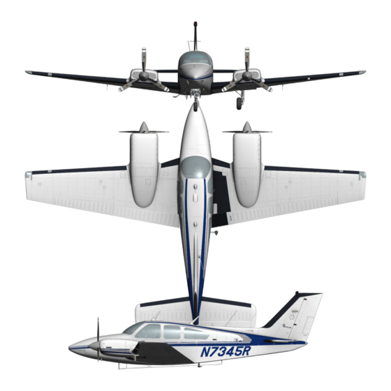
Page 7: Airplane Three View
BEECHCRAFT Baron B55 Aircraft Three View Figure 1 Version 1.0 – 15 May 2012... -
Page 8: Ground Turning Clearance
BEECHCRAFT Baron B55 Aircraft Turning Clearance Figure 2 A. Radius for Wing Tip ………………………………….…. 29 feet, 6 inches B. Radius for Nose Wheel ……………………………….. 12 feet, 2 inches C. Radius for Inside Gear ………………………………… 5 feet, 9 inches D. Radius for Outside Gear …………………………….. 15 feet, 7 inches Version 1.0 –... -
Page 9: Descriptive Data
BEECHCRAFT Baron B55 DESCRIPTIVE DATA ENGINES Two Continental IO-520-C fuel injected, air cooled six cylinder, horizontally-opposed engines each rated at 285 horsepower at 2700 rpm. Take-off and Maximum Continuous Power Full throttle and 2700 rpm Maximum One-Engine Inoperative Power Full throttle and 2700 rpm Cruise Climb Power 25.0 in. -
Page 10: Fuel
BEECHCRAFT Baron B55 McCAULEY 2 Blade Hubs: 2AF34C55 Blades: 78FF-O Pitch setting at 30 inch Station: Low 1 5°; high 79° Diameter: Maximum 78 inches. Minimum 76 inches FUEL Aviation Gasoline 1OOLL (blue) preferred. 100 (green) minimum grade. STANDARD SYSTEM: Total Capacity 106 Gallons Total Usable... -
Page 11: Baggage
BEECHCRAFT Baron B55 BAGGAGE Aft cabin compartment 35 cu ft STD Aft Hatshelf 1. 7 cu ft Extended rear compartment 10 cu ft Nose compartment 12 cu ft SPECIFIC LOADINGS Wing Loading 25.6 lbs/sq ft Power Loading 9.8 lbs;hp SYMBOLS, ABBREVIATIONS AND TERMINOLOGY The following Abbreviations and Terminologies have been listed for convenience and ready interpretation where used within this handbook. -
Page 12: Meteorological Terminology
BEECHCRAFT Baron B55 Maximum Flap Extended Speed is the highest speed permissible with wing flaps in a prescribed extended position. Maximum Landing Gear Extended Speed is the maximum speed at which an airplane can be safely flown with the landing gear extended. Maximum Landing Gear Operating Speed is the maximum speed at which the landing gear can be safely extended or retracted. -
Page 13: Power Terminology
BEECHCRAFT Baron B55 Wind: The wind velocities recorded as variables on the charts of this handbook are to be understood as the headwind or tailwind components of the reported winds. POWER TERMINOLOGY Takeoff/Max. Continuous …… The highest power rating not limited by time. Cruise Climb …………………..……... -
Page 14: Weight And Balance Terminology
BEECHCRAFT Baron B55 Accelerate- Go Distance ……… The distance required to accelerate to a specified speed and, assuming failure of an engine at the instant that speed is attained, feather inoperative propeller and continue takeoff on the remaining engine to a height of 50 feet. MEA ……………………………………... - Page 15 BEECHCRAFT Baron B55 Maximum Ramp Weight …… Maximum weight approved for ground maneuvering. (It includes weight of start, taxi, and run up fuel). Maximum Takeoff Weight …. Maximum weight approved for the start of the take off run. Maximum Landing Weight …. Maximum weight approved for the landing touchdown. Zero Fuel Weight ………………..
- Page 16 BEECHCRAFT Baron B55 SECTION 2 LIMITATIONS TABLE OF CONTENTS Airspeed Limitations ……………………………………………………………………….………………………. Airspeed Indicator Markings …………………………………………………….…………………………….. Power Plant Limitations …………………………………………………………………….……………………. Engines ……………………………………………………………………………….……………………… Fuel …………………………………………………………………………………….……………………… Oil ……………………………………………………………………………………….…………………….. Propellers …………………………………………………………………………….……………………. Starters -Time for Cranking ………………………………………………………………….…….…………… Power Plant Instrument Markings ………………………………………………….…….………………… Oil Temperature ……………………………………………………………….…….…………………. Oil Pressure …………………………………………………………………….……..………………….
-
Page 17: Airspeed Limitations
BEECHCRAFT Baron B55 The limitations included in this section have been approved by the Federal Aviation Administration. The following limitations must be observed in the operation of this airplane. Figure 3 Version 1.0 – 15 May 2012 [17]... -
Page 18: Airspeed Indicator Markings
BEECHCRAFT Baron B55 Figure 4 POWER PLANT LIMITATIONS ENGINES Two Continental IO-520-C fuel injected, air-cooled six cylinder, horizontally-opposed engines each rated at 285 horsepower at 2700 rpm. Take-off and Maximum continuous power Full throttle, 2700 rpm Maximum Cylinder Head Temperature 460°F Maximum Oil Temperature 22 5°F... -
Page 19: Starters -Time For Cranking
BEECHCRAFT Baron B55 Pitch Setting at 30 inch Station: Low 1 6.0°; Feathered 80. 0° Diameter: 78 inches, cut-off permitted to 76. 5 inches or 2 Blade Hubs: BHC- C2YF-2CH Blades: C8465-6 Pitch Setting at 30 inch Station: Low 1 6.0°; Feathered 80.0° Diameter: 78 inches, cut-off permitted to 76.5 inches HARTZELL 1 3 Blade Hubs: PHC-C3YF-2F Blades: FC7663-2R... -
Page 20: Fuel Pressure
BEECHCRAFT Baron B55 FUEL PRESSURE Minimum (Red Radial) 1.5 psi Operating Range (Green Arc) 5 to17 psi Cruise Power (Heavy Green Arc) 5 to 9.5 psi Maximum (Red Radial) 1 7.5 psi MANIFOLD PRESSURE Operating Range (Green Arc) 15 to 29 .6 in.Hg Maximum (Red Radial) 29.6 in.Hg TACHOMETER... -
Page 21: Cg Limits
BEECHCRAFT Baron B55 CG LIMITS Forward Limits: 74 inches aft of datum at 3800 lbs and under, then straight line variation to 77. inches aft of datum at 4740 lbs, then straight line variation to 8 1 .0 inches aft of datum at gross weight of 51 00 lbs. -
Page 22: Legend
BEECHCRAFT Baron B55 should be maintained to assure continued airworthiness. If deviations from the installed equipment were not permitted, or if the operating rules did not provide for various flight conditions, the airplane could not be flown unless all equipment was operable. With appropriate limitations, the operation of every system or component installed in the airplane is not necessary, when the remaining operative instruments and equipment provide for continued safe operation. -
Page 23: Oxygen Requirements
BEECHCRAFT Baron B55 OXYGEN REQUIREMENTS One mask for minimum crew and one mask passengers with an adequate supply of oxygen when operating above 12,500 feet (MSL). Refer to FAR 91 .32 for variations concerning supplemental oxygen requirements for a particular flight. MAXIMUM PASSENGER SEATING CONFIGURATION Five (5) passengers and one (1) pilot SEATING... - Page 24 BEECHCRAFT Baron B55 SECTION 3 EMERGENCY PROCEDURES TABLE OF CONTENTS Emergency Airspeeds ……………………………………………………………………………………………… One Engine Operation …………………..…………………..………………………………………. Determining Inoperative Engine ………….………………………………….……………………………… One -Engine Inoperative Procedures …………………………..………….…………………………….. Engine Failure During Take-Off ………………………..………………………………………… Engine Failure After Lift -off and In Flight ………………….……………………………….. Air Start ……………………………………………………………………………………………………………………...
-
Page 25: Emergency Airspeeds
BEECHCRAFT Baron B55 All airspeeds quoted in this section are indicated airspeeds (lAS) and assume zero instrument error. EMERGENCY AIRSPEEDS (5100 LBS) One-Engine - Inoperative BestAngle-of -Climb (Vx) 91 kts/105 mph One-Engine -Inoperative Best Rate-of -Climb (Vy) 100 kts/115 mph Air Minimum Control Speed (VMCA) 78 kts/90 mph One-Engine -Inoperative Enroute Climb... -
Page 26: One-Engine Inoperative Procedures
BEECHCRAFT Baron B55 ONE-ENGINE INOPERATIVE PROCEDURES ENGINE FAILURE DURING TAKE-OFF 1. Throttle - CLOSED 2. Braking - MAXIMUM If insufficient runway remains for stopping: 3. Fuel Selector Valves - OFF 4. Battery, Generator/Alternator, and Magneto/Start Switches - OFF ENGINE FAILURE AFTER LIFT-OFF AND IN FLIGHT An immediate landing is advisable regardless of take-off weight. -
Page 27: Air Start
BEECHCRAFT Baron B55 AIR START CAUTION The pilot should determine the reason for engine failure before attempting an air start. 1. Fuel Selector Valve - ON 2. Throttle - SET approximately 1/4 travel 3. Mixture Control - FULL RICH, below 5000 ft (1; 2 travel above 5,000 ft) 4. -
Page 28: Engine Fire In Flight
BEECHCRAFT Baron B55 ENGINE FIRE IN FLIGHT Shut down the affected engine according to the following procedure and land immediately. Follow the applicable single-engine procedures in this section. 1. Fuel Selector Valve - OFF 2. Mixture Control - IDLE CUT-OFF 3. -
Page 29: Landing Emergencies
BEECHCRAFT Baron B55 LANDING EMERGENCIES GEAR-UP LANDING If possible, choose firm sod or foamed runway. When assured of reaching landing site: 1. Cowl Flaps - CLOSED 2. Wing Flaps - AS DESIRED 3. Throttles - CLOSED 4. Fuel Selector Valves - OFF 5. -
Page 30: Systems Emergencies
BEECHCRAFT Baron B55 SYSTEMS EMERGENCIES ONE-ENGINE INOPERATIVE OPERATION ON CROSSFEED NOTE The fuel cross-feed system is to be used only during emergency conditions in level flight only. Left engine inoperative: 1. Right Aux Fuel Pump - LOW 2. Left Fuel Selector Valve - OFF 3. -
Page 31: Illumination Of Alternator-Out Light
BEECHCRAFT Baron B55 ILLUMINATION OF ALTERNATOR OUT LIGHT In the event of the illumination of a single ALTERNATOR OUT light: 1. Check the respective loadmeter for load indication a. No Load - Turn off affected alternator b. Regulate load In the event of the illumination of both ALTERNATOR OUT lights: 1. -
Page 32: Landing Gear Manual Extension
BEECHCRAFT Baron B55 (1) Both ALT Switches - OFF (2) Minimize electrical load since only battery power will be available LANDING GEAR MANUAL EXTENSION Reduce airspeed before attempting manual extension of the landing gear. 1. LDG GR MOTOR Circuit Breaker - PULL 2. -
Page 33: Ice Protection
BEECHCRAFT Baron B55 ICE PROTECTION SURFACE DEICE SYSTEM a. Failure of AUTO Operation (1) Surface Deice Switch - MANUAL (Do not hold more than 8 seconds) CAUTION The boots will inflate only as long as the switch is held in the MANUAL position. -
Page 34: Emergency Exits
BEECHCRAFT Baron B55 conditions (especially on the ground), the possibility of obstructed static ports should be considered. Partial obstructions will result in the rate of climb indication being sluggish during a climb or descent. Verification of suspected obstruction is possible by switching to the emergency system and noting a sudden sustained change in rate of climb. -
Page 35: Simulated One-Engine Inoperative
BEECHCRAFT Baron B55 SIMULATED ONE ENGINE INOPERATIVE ZERO THRUST (Simulated Feather) Use the following power setting (only on one engine at a time) to establish zero thrust. Use of this power setting avoids the difficulties of restarting an engine and preserves the availability of engine power. - Page 36 BEECHCRAFT Baron B55 SECTION 4 NORMAL PROCEDURES TABLE OF CONTENTS Airspeeds for Safe Operation (5100 Lbs.) ……………………………………………………………….. Preflight Inspection ………………………………………………………………………………………………… Before Starting ……………………………………………………………………………………………………….. Starting ………………………………………………………………………………………………………………….. After Starting and Taxi ……………………………………………………………………………………………. Before Takeoff ………………………………………………………………………………………………………… Take-Off ………………………………………………………………………………………………………………….. Maximum Performance Climb …………………………………………………………………………………. Cruise Climb …………………………………………………………………………………………………………….. Cruise ………………………………………………………………………………………………………………………..
-
Page 37: Airspeeds For Safe Operation (5100 Lbs)
BEECHCRAFT Baron B55 All airspeeds quoted in this section are indicated airspeeds (IAS) and assume zero instrument error. AIRSPEEDS FOR SAFE OPERATION (5100 LBS) Maximum Demonstrated Crosswind Component 22kts/25mph Takeoff: Lift-off 84kts/97mph 50-ft Speed 91kts/105mph Two-Engine Best Angle-of-Climb (Vx) 84kts/97mph Two-Engine Best Rate-of-Climb (Vy) 107kts/123mph Cruise Climb... - Page 38 BEECHCRAFT Baron B55 b. Baggage Door - SECURE c. Static Port - UNOBSTRUCTED d. Emergency Locator Transmitter - ARMED 3. EMPENNAGE: a. Control Surfaces, Tabs and Deice Boots - CHECK CONDITION, SECURITY, AND ATTACHMENT b. Tail Cone, Tail Light, and Rudder Beacon - CHECK c.
-
Page 39: Before Starting
BEECHCRAFT Baron B55 d. Fuel Drains -DRAIN e. Engine Oil - CHECK QUANTITY, CAP AND DOOR SECURE f. Engine Cowling and Doors - CHECK CONDITION AND SECURITY g. Propeller - EXAMINE FOR NICKS, SECURITY AND OIL LEAKS h. Engine Air Intake - EXAMINE FOR OBSTRUCTIONS i. -
Page 40: Starting
BEECHCRAFT Baron B55 STARTING 1. Throttle Position - APPROXIMATELY 1/2 IN. OPEN 2. Propeller Control - LOW PITCH (high rpm) 3. Mixture Control - FULL RICH NOTE If the engine is hot and the ambient temperature is 90°F or above, place mixture control in IDLE CUT-OFF, switch aux fuel pump to HIGH for 30 to 60 seconds, then OFF. -
Page 41: After Starting And Taxi
BEECHCRAFT Baron B55 CAUTION Low voltage, high ammeter or loadmeter readings, dimming of lights, or excessive noise in radio receivers could be indications that problems are developing in the starter system. A noted change in such normal conditions could indicate prolonged starter motor running and the engine should be shut down. -
Page 42: Take-Off
BEECHCRAFT Baron B55 15. Trim- AS REQUIRED FOR TAKE-OFF 16. Flaps - CHECK AND SET FOR TAKE-OFF 17. Flight Controls - CHECK PROPER DIRECTION, FULL TRAVEL AND FREEDOM OF MOVEMENT 18. Doors and Windows - LOCKED 19. Parking Brake - OFF TAKE-OFF Take-Off Power …………………………………………………………... -
Page 43: Leaning Using Egt
BEECHCRAFT Baron B55 LEANING USING THE EXHAUST GAS TEMPERATURE INDICATOR (EGT) The system consists of a thermocouple type exhaust gas temperature (EGT) probe mounted in the right side of each exhaust system. This probe is connected to an indicator on the right side of the instrument panel. -
Page 44: Balked Landing
OXYGEN SYSTEM NOTE The optional onboard oxygen system is not modeled in the MilViz Beechcraft Baron 55. WARNING NO SMOKING permitted when using oxygen. Version 1.0 – 15 May 2012... -
Page 45: Preflight
BEECHCRAFT Baron B55 PREFLIGHT 1. Check Oxygen Pressure Gage for pressure reading. 2. Determine percent of full system. 3. Multiply oxygen duration in minutes by percent of full system. EXAMPLE People ……………………………..…………….. 5 Gage Pressure ……………………..………… 1500psi Percent Capacity (from chart) …..….. Cylinder Capacity (full) ………………….. -
Page 46: Cold Weather Operation
BEECHCRAFT Baron B55 Oxygen Capacity and Duration Figure 6 COLD WEATHER OPERATION PREFLIGHT INSPECTION In addition to the normal preflight exterior inspection, remove ice, snow and frost from the wings, tail, control surfaces and hinges, propellers, windshield, fuel cell filler caps and fuel vents. If you have no way of removing these formations of ice, snow, and frost leave the airplane on the ground, as these deposits will not blow off. -
Page 47: Engines
BEECHCRAFT Baron B55 ENGINES Use engine oil in accordance with Consumable Materials in the SERVICING section. Always pull the propeller through by hand several times to clear the engine and "limber up" the cold, heavy oil before using the starter. This will also lessen the load on the battery if an auxiliary power unit is not used. Under very cold conditions, it may be necessary to preheat the engine prior to a start. -
Page 48: Taxiing
BEECHCRAFT Baron B55 4. Auxiliary Power Unit - SET OUTPUT (27.0 to 28.5 volts) 5. Auxiliary Power Unit - ON 6. Right Engine - START (use normal start procedures) 7. Auxiliary Power Unit - OFF (after engine has been started) 8. -
Page 49: Surface Deice System
BEECHCRAFT Baron B55 CAUTION The emergency static air valve should be in the OFF NORMAL position when the system is not needed. 2. SURFACE DEICE SYSTEM a. BEFORE TAKE-OFF (1) Throttles - 2000 RPM (2) Surface Deice Switch - AUTO (UP) (3) Deice Pressure - 9 to 20 PSI (while boots are inflating) (4) Wing Boots - CHECK VISUALLY FOR INFLATION AND HOLD DOWN b. -
Page 50: Propeller And Windshield Anti-Ice System
BEECHCRAFT Baron B55 b. IN FLIGHT (1) Propeller Deice Switch - ON. The system may be operated continuously in flight and will function automatically until the switch is turned OFF. (2) Relieve propeller imbalance due to ice by increasing rpm briefly and return1ng to the desired setting. -
Page 51: Windshield Defogging
BEECHCRAFT Baron B55 7. WINDSHIELD DEFOGGING a. Defrost Control - PUSH ON b. Pilots Storm Window - OPEN, AS REQUIRED ENGINE BREAK-IN INFORMATION Refer to Systems section. PRACTICE DEMONSTRATION OF Vmca Vmca demonstration may be required for multi-engine pilot certification. The following procedure shall be used at a safe altitude of at least 5000 feet above the ground in clear air only. - Page 52 BEECHCRAFT Baron B55 SECTION 5 PERFORMANCE TABLE OF CONTENTS Introduction to Performance and Flight Planning ………………………………………………….. Conditions ……………………………………………………………………………………………………………… Comments Pertinent to the Use of Performance Graphs ………………………………………. Performance Graphs ……………………………………………………………………………………………… Airspeed Calibration - Normal System ……………………………………………………………………. Altimeter Correction - Normal System ……………………………………………………………………. Airspeed Calibration - Alternate System ………………………………………………………………….
- Page 53 BEECHCRAFT Baron B55 INTRODUCTION TO PERFORMANCE AND FLIGHT PLANNING All airspeeds quoted in this section are indicated airspeeds (IAS) except as noted and assume zero instrument error. The graphs and tables in this section present performance information for takeoff, climb, landing and flight planning at various parameters of weight, power, altitude, and temperature.
- Page 54 BEECHCRAFT Baron B55 Runway 21 Length 10,000ft To determine pressure altitude at origin and destination airports, add 100 feet to field elevation for each .1 in. Hg below 29.92, and subtract 100 feet from field elevation for each .1 in. Hg above 29.92. Pressure Altitude at DEN: 29.92 - 29.60 = .32 in.
- Page 55 BEECHCRAFT Baron B55 NOTE Since 4100 feet is less than the available field length (10,010 ft), the accelerate-stop procedure can be performed at any weight. Take-off at 5100lbs can be accomplished. However, if an engine failure occurs before becoming airborne, the accelerate-stop procedure must be performed. The following example assumes the airplane is loaded so that the take-off weight is 4550 pounds.
- Page 56 BEECHCRAFT Baron B55 The above results are illustrated below: Figure 8 The following calculations provide information for the flight planning procedure. All examples are presented on the performance graphs. A take-off weight of 5100 pounds has been assumed. Enter the Time, Fuel, and Distance to Climb graph at 15°C to 5650 feet and to 5100 pounds. Also enter at -5°C to 11,500 feet and to 5100 pounds.
- Page 57 BEECHCRAFT Baron B55 Enter the table for recommended cruise power - 24 in. Hg, 2300 rpm at 10,000ft 12,000 ft. ISA and ISA + 20°C. Figure 9 Interpolate for 11,500 feet and the temperature for the appropriate route segment. Results of the interpolations are: Figure 10 NOTE...
- Page 58 BEECHCRAFT Baron B55 Figure 11 *Distance required to climb or descend has been subtracted from segment distance. TIME - FUEL - DISTANCE Figure 12 Total Flight Time: 1 hour, 51 minutes Block Speed: 321 NM-:- 1 hour, 51 minutes= 174kts/200mph Reserve Fuel: (45 minutes at Economy Cruise Power): Enter the cruise power settings table for Economy Cruise Power at 11,500 feet for ISA (assume ISA Fuel Flow Rate).
- Page 59 BEECHCRAFT Baron B55 Assumed ramp weight = 5121 lbs Estimated fuel from DEN to AMA = 41.4 gal (248lbs) Estimated landing weight = 5121 - 248 = 4873lbs Examples have been provided on the performance graphs. The above conditions have been used throughout.
- Page 60 BEECHCRAFT Baron B55 Figure 13 Version 1.0 – 15 May 2012 [60]...
- Page 61 BEECHCRAFT Baron B55 Figure 14 Version 1.0 – 15 May 2012 [61]...
- Page 62 BEECHCRAFT Baron B55 Figure 15 Version 1.0 – 15 May 2012 [62]...
- Page 63 BEECHCRAFT Baron B55 Figure 16 Version 1.0 – 15 May 2012 [63]...
- Page 64 BEECHCRAFT Baron B55 Figure 17 Version 1.0 – 15 May 2012 [64]...
- Page 65 BEECHCRAFT Baron B55 Figure 18 Version 1.0 – 15 May 2012 [65]...
- Page 66 BEECHCRAFT Baron B55 Figure 19 Version 1.0 – 15 May 2012 [66]...
- Page 67 BEECHCRAFT Baron B55 Figure 20 Version 1.0 – 15 May 2012 [67]...
- Page 68 BEECHCRAFT Baron B55 Figure 21 Version 1.0 – 15 May 2012 [68]...
- Page 69 BEECHCRAFT Baron B55 Figure 22 Version 1.0 – 15 May 2012 [69]...
- Page 70 BEECHCRAFT Baron B55 Figure 23 Version 1.0 – 15 May 2012 [70]...
- Page 71 BEECHCRAFT Baron B55 Figure 24 Version 1.0 – 15 May 2012 [71]...
- Page 72 BEECHCRAFT Baron B55 Figure 24 Version 1.0 – 15 May 2012 [72]...
- Page 73 BEECHCRAFT Baron B55 Figure 25 Version 1.0 – 15 May 2012 [73]...
- Page 74 BEECHCRAFT Baron B55 Figure 26 Version 1.0 – 15 May 2012 [74]...
- Page 75 BEECHCRAFT Baron B55 Figure 27 Version 1.0 – 15 May 2012 [75]...
- Page 76 BEECHCRAFT Baron B55 Figure 28 Version 1.0 – 15 May 2012 [76]...
- Page 77 BEECHCRAFT Baron B55 Figure 29 Version 1.0 – 15 May 2012 [77]...
- Page 78 BEECHCRAFT Baron B55 Figure 30 Version 1.0 – 15 May 2012 [78]...
- Page 79 BEECHCRAFT Baron B55 Figure 31 Version 1.0 – 15 May 2012 [79]...
- Page 80 BEECHCRAFT Baron B55 Figure 32 Version 1.0 – 15 May 2012 [80]...
- Page 81 BEECHCRAFT Baron B55 Figure 33 Version 1.0 – 15 May 2012 [81]...
- Page 82 BEECHCRAFT Baron B55 Figure 34 Version 1.0 – 15 May 2012 [82]...
- Page 83 BEECHCRAFT Baron B55 Figure 35 Version 1.0 – 15 May 2012 [83]...
- Page 84 BEECHCRAFT Baron B55 Figure 36 Version 1.0 – 15 May 2012 [84]...
- Page 85 BEECHCRAFT Baron B55 Figure 37 Version 1.0 – 15 May 2012 [85]...
- Page 86 BEECHCRAFT Baron B55 Figure 38 Version 1.0 – 15 May 2012 [86]...
- Page 87 BEECHCRAFT Baron B55 Figure 39 Version 1.0 – 15 May 2012 [87]...
- Page 88 BEECHCRAFT Baron B55 Figure 40 Version 1.0 – 15 May 2012 [88]...
- Page 89 BEECHCRAFT Baron B55 Figure 41 Version 1.0 – 15 May 2012 [89]...
- Page 90 BEECHCRAFT Baron B55 Figure 42 Version 1.0 – 15 May 2012 [90]...
- Page 91 BEECHCRAFT Baron B55 Figure 43 Version 1.0 – 15 May 2012 [91]...
- Page 92 BEECHCRAFT Baron B55 Figure 44 Version 1.0 – 15 May 2012 [92]...
- Page 93 BEECHCRAFT Baron B55 SECTION 6 WEIGHT AND BALANCE TABLE OF CONTENTS Weighing Instructions …………………………………………………………………………………..……….…. Basic Empty Weight and Balance Form …………………………………………………………………….. Weight and Balance Record ……………………………………………………………………………………… Loading Instructions …………………………………………………………………………………………………. Seating, Baggage and Equipment Arrangements ……………………………………………………… Moment Limits vs Weight Table ……………………………………………………………………………….. Moment Limits vs Weight Graph ……………………………………………………………………………….
-
Page 94: Weighing Instructions
BEECHCRAFT Baron B55 WEIGHING INSTRUCTIONS Periodic weighing of the airplane may be required to keep the Basic Empty Weight current. All changes to the airplane affecting weight and balance are the responsibility of the airplane's operator. 1. Three jack points are provided for weighing: two on the wing front spar at Fuselage Station 83.1 and one on the aft fuselage at Fuselage Station 271.0. -
Page 95: Basic Empty Weight And Balance Form
BEECHCRAFT Baron B55 Figure 45 Figure 46 Version 1.0 – 15 May 2012 [95]... - Page 96 BEECHCRAFT Baron B55 NOTE Each new airplane is delivered with a completed sample loading, empty weight and center of gravity, and equipment list, all pertinent to that specific airplane. It is the owner's responsibility to ensure that changes in equipment are reflected in a new weight and balance and in an addendum to the equipment list.
-
Page 97: Weight And Balance Record
BEECHCRAFT Baron B55 Figure 47 Version 1.0 – 15 May 2012 [97]... - Page 98 BEECHCRAFT Baron B55 Figure 48 Version 1.0 – 15 May 2012 [98]...
-
Page 99: Loading Instructions
BEECHCRAFT Baron B55 LOADING INSTRUCTIONS It is the responsibility of the airplane operator to ensure that the airplane is properly loaded. At the time of delivery, Beech Aircraft Corporation provides the necessary weight and balance data to compute individual loadings. All subsequent changes in airplane weight and balance are the responsibility of the airplane owner and/or operator. - Page 100 BEECHCRAFT Baron B55 Figure 50 Version 1.0 – 15 May 2012 [100]...
-
Page 101: Moment Limits Vs Weight Graph
BEECHCRAFT Baron B55 Figure 51 Version 1.0 – 15 May 2012 [101]... - Page 102 BEECHCRAFT Baron B55 Figure 52 Version 1.0 – 15 May 2012 [102]...
- Page 103 BEECHCRAFT Baron B55 Figure 53 Version 1.0 – 15 May 2012 [103]...
- Page 104 BEECHCRAFT Baron B55 Figure 54 Version 1.0 – 15 May 2012 [104]...
-
Page 105: Computing Procedure
BEECHCRAFT Baron B55 COMPUTING PROCEDURE 1. Record the Basic Empty Weight and Moment from the Basic Empty Weight and Balance form (or from the latest superceding form) under the Basic Empty Condition block. The moment must be divided by 100 to correspond to Useful Load Weights and Moments tables. 2. -
Page 106: Sample Weight And Balance Loading Form
BEECHCRAFT Baron B55 Figure 55 Version 1.0 – 15 May 2012 [106]... -
Page 107: Weight And Balance Loading Form
BEECHCRAFT Baron B55 Figure 56 Version 1.0 – 15 May 2012 [107]... -
Page 108: Useful Load Weights And Moments
BEECHCRAFT Baron B55 Figure 57 Version 1.0 – 15 May 2012 [108]... -
Page 109: Occupants
BEECHCRAFT Baron B55 Figure 58 Version 1.0 – 15 May 2012 [109]... - Page 110 BEECHCRAFT Baron B55 Figure 59 Version 1.0 – 15 May 2012 [110]...
-
Page 111: Cargo
BEECHCRAFT Baron B55 Figure 60 Version 1.0 – 15 May 2012 [111]... -
Page 112: Usable Fuel
BEECHCRAFT Baron B55 Figure 61 Version 1.0 – 15 May 2012 [112]... -
Page 113: Baggage
BEECHCRAFT Baron B55 SECTION 7 SYSTEMS TABLE OF CONTENTS Airframe ………………………………………………………..…………………………………………………………. Flight Controls ……………………………………………..…………………………………………………………… Control Surfaces …………………………..……………………………………………………………. Control Column ……………………………..……………………………………………………………. Rudder Pedals ……………………………..……………………………………………………………… Trim Controls ………………………………..…………………………………………………………….. Instrument Panel ……………………………………..………………………………………………………………. Flight Instruments ……………………………………………………………………………………….. Power Plant Instruments …………………………………………………………………………….. Ground Control …………………………………………………………………………………………………………. Wing Flaps ……………………………………………………………………………………………………. Landing Gear System ……………………………………………………………………………………. - Page 114 BEECHCRAFT Baron B55 Fuel System ………………………………………………………………………………………………………………. Fuel Pressure Indicator ………………………………………………………………………………… Schematic ……………………………………………………………………………………………………. Fuel Crossfeed …………………………………………………………………………………………….. Auxiliary Fuel Pumps ……………………………………………………………………………………. Partial Fuel Loading ……………………………………………………………………………………… Fuel Required for Flight ……………………………………………………………………………….. Electrical System ………………………………………………………………………………………………………. Schematic ……………………………………………………………………………………………………. Battery …………………………………………………………………………………………………………. Generators …………………………………………………………………………………………………… Alternators …………………………………………………………………………………………………… Starters ………………………………………………………………………………………………………… External Power ……………………………………………………………………………………………..
-
Page 115: Airframe
Check for full freedom of movement after repositioning the control. NOTE The MilViz Baron 55 models the optional dual control column; therefore the T-handle latch is removed as part of this STC upgrade. The optional dual control column is required for flight instruction. -
Page 116: Instrument Panel
BEECHCRAFT Baron B55 FLIGHT INSTRUMENTS The flight instruments are located on a floating panel directly in front of the pilot's seat (see figure 62). Standard flight instrumentation includes attitude and directional gyros, airspeed, altimeter, vertical speed, turn coordinator and a clock. A magnetic compass is mounted above the instrument panel and an outside air temperature indicator is located on the left side panel. -
Page 117: Wing Flaps
BEECHCRAFT Baron B55 The wing flaps are controlled by a three position switch (figure 66) placarded UP-OFF-DOWN. The switch is located on the control console and must be pulled out of a detent before operating. Any position within flap travel may be attained by returning the switch to the OFF position. -
Page 118: Landing Gear System
BEECHCRAFT Baron B55 Figure 68 LANDING GEAR SYSTEM CAUTION If a reduced power throttle position exists when throwing over the control column, it will be necessary to momentarily move the throttle levers forward for passage of the control column. The landing gear is operated through adjustable linkage connected to an actuator assembly mounted beneath the front seats. -
Page 119: Control Switch
MANUAL EXTENSION NOTE Manual extension of the landing gear is not modeled in the MilViz Baron The landing gear can be manually extended, but not retracted, by operating the handcrank on the rear of the pilot's seat. The landing gear handle must be in the down position and the landing gear MOTOR circuit breaker must be pulled before manually extending the gear. -
Page 120: Brakes
BEECHCRAFT Baron B55 For electrical retraction of the landing gear after a practice manual extension use procedures outlined in the EMERGENCY PROCEDURES section. If the landing gear was extended for emergency reasons, do not move any landing gear controls or reset any switches or circuit breakers until the aircraft is on jacks, to prevent a gear retraction on the ground. -
Page 121: Nose Baggage/Cargo Compartment
BEECHCRAFT Baron B55 NOSE BAGGAGE/CARGO COMPARTMENT The forward baggage/cargo compartment is easily accessible through a large door on the right side of the nose. The door, hinged at the top, swings upward, clear of the loading area. Loading within this area must be within the limitations according to the WEIGHT AND BALANCE section. -
Page 122: Doors, Windows And Exits
BEECHCRAFT Baron B55 the seat back For the fifth and sixth passenger seats, the strap is contained m an inertia reel attached to the upper fuselage side structure just aft of the seat back and is covered with an escutcheon. NOTE The seat belt is independent of the shoulder harness, but the outboard seat belt and the shoulder harness must be connected for stowage when... -
Page 123: Emergency Exits
2. Route cable and rudder lock around right side of control column, position pedals in aft position and install lock in rudder pedals. POWER PLANTS The MilViz BEECHCRAFT BARON B-55 is powered by two Continental 10-520-M six-cylinder, horizontally opposed, fuel injected engines rated at 280 hp at 2700 rpm. POWER PLANT CONTROLS PROPELLER, THROTILE AND MIXTURE The control levers are grouped along the upper face of the control console. -
Page 124: Induction Air
BEECHCRAFT Baron B55 INDUCTION AIR Induction air is available from filtered ram air or alternate air. Filtered ram air enters from above the engine inside the nacelle area. Should the filter become obstructed, a spring-loaded door on the side of the plenum will open automatically and the induction system will operate on alternate air taken from the nacelle area. -
Page 125: Propeller Synchronizer
BEECHCRAFT Baron B55 PROPELLER SYNCHRONIZER The propeller synchronizer automatically matches the rpm of both propellers. The system's range of authority is limited to approximately 25 rpm. Normal governor operation is unchanged but the synchronizer will continuously monitor propeller rpm and adjust one governor as required. A magnetic pickup mounted in each propeller governor transmits electric pulses to a transistorized control box installed behind the pedestal. -
Page 126: Fuel Pressure Indicator
BEECHCRAFT Baron B55 Fuel quantity is measured by float type transmitter units which transmit the common level indication to a single indicator gauge for each respective wing system (figure 63). FUEL PRESSURE INDICATOR The fuel pressure indicator (see Figure 74) registers metered fuel pressure at the fuel injection manifold valve. -
Page 127: Fuel Crossfeed
BEECHCRAFT Baron B55 Figure 74 In the cruise power range the green sectors cover the fuel pressure required from 45% to 75% power. The lower edge of each sector is the normal-lean setting and the upper range is the best power setting for that particular power range. -
Page 128: Partial Fuel Loading
BEECHCRAFT Baron B55 pressure position should not be selected while the engine is operating except in the event of engine- driven pump failure since the high pressure mode supplies a greater pressure than can be accepted by the injection system during normal operation. PARTIAL FUEL LOADING A visual fuel level sight gage for partial loading has been provided in each wing leading edge, outboard of the engine nacelle. -
Page 129: Schematic
BEECHCRAFT Baron B55 Figure 78 BATTERY One 17 ampere-hour, 24-volt lead acid battery is standard. Two 25 ampere-hour, 12-volt lead acid batteries, connected in series are offered as options. The battery installation is located beneath the floor of the nose baggage compartment. Battery servicing procedures are described in the SERVICING section. The battery can be turned off in flight and the alternator/generators will remain online. -
Page 130: Alternators
BEECHCRAFT Baron B55 instrument panel. On TC-1913, TC-1936 and after, the generators are protected by current limiters instead of circuit breakers. ALTERNATORS Two 50-ampere, 24-volt, belt-driven alternators are controlled by two transistorized electronic voltage regulators. Only one regulator is operable in the system at any one time. The remaining regulator is used as an alternate or standby unit. -
Page 131: Lighting Systems
BEECHCRAFT Baron B55 LIGHTING SYSTEM INTERIOR LIGHTING Interior lights are controlled by a series of three rheostat knobs located on the center console below the trim wheels (figure 81). A courtesy light located in the door will be illuminated any time the door is in the open position. The cabin dome light is operated by an OFF-ON switch forward of the light. -
Page 132: Heating And Ventilation System
BEECHCRAFT Baron B55 HEATING AND VENTILATION SYSTEM CABIN HEATING A combustion heater on the nose cone supplies heated air to the cabin (see figure 83). Outlets are located forward of the pilot and copilot seats, at the rear of the copilot's seat, and at the rear of the right passenger seat. -
Page 133: Environmental Schematic
BEECHCRAFT Baron B55 The PILOT AIR and CO-PILOT AIR controls can be used to regulate the amount of air distributed to the two rear outlets. Figure 83 HEATER BLOWER When the three-position switch on the pilot's subpanel is placed in either the HEATER position or the BLOWER position, the blower will operate if the landing gear is in the extended position and the CABIN AIR control is more than halfway in. -
Page 134: Exhaust Vents
NOTE The function and operation of the onboard oxygen system is not modeled on the MilViz Baron 55. PITOT AND STATIC SYSTEM The pitot and static system provides a source of impact and static air for the operation of flight instruments. -
Page 135: Vacuum System
BEECHCRAFT Baron B55 The emergency static air source is designed to provide a source of static pressure to the instruments from inside the fuselage should the outside static air ports become blocked. An abnormal reading of the instruments supplied with static air could indicate a restriction in the outside static air ports. A lever on the lower sidewall adjacent to the pilot, is placarded OFF NORMAL, ON EMERGENCY. -
Page 136: Propeller And Windshield
NOTE The function and operation of the fluid flow style propeller and windshield anti-ice systems are not modeled on the MilViz Baron 55. The system is designed to prevent the formation of ice. Always place the system in operation before encountering icing conditions. -
Page 137: Electrothermal Propeller Deice
ELECTROTHERMAL PROPELLER DEICE (2 and 3 BLADES) NOTE The electrothermal propeller deice system is modeled on the MilViz Baron 55. Propeller ice removal is accomplished by the electrically heated deice boots bonded to each propeller blade. The system uses the aircraft electrical power to heat portions of the deice boots in a sequence controlled by a timer. - Page 138 BEECHCRAFT Baron B55 operations during the break-in period, avoiding altitudes above 8000 feet. Interrupt cruise power every 30 minutes or so by smoothly advancing to take-off power settings for about 30 seconds, then returning to cruise power settings. Avoid long power-off descents especially during the break-in period. Maintain sufficient power during descent to permit cylinder head temperatures to remain in the green arc.
- Page 139 Kade Bellaney DISCLAIMER Note: While this POH was designed to strongly replicate the actual Beechcraft Baron 55 POH, it must be remembered that this document is intended merely to support virtual flight operations of the MilViz Baron 55 in FSX. Nothing written in this document, nor in the modeling and presentation of the MilViz Baron 55, should be used to support actual flight operations or to satisfy formal flight training without certification by the appropriate national aviation authorities.
Need help?
Do you have a question about the Beechcraft Baron 55 and is the answer not in the manual?
Questions and answers