
Summary of Contents for QVTOOLS POWER KING PK0702
- Page 1 Commercial and Industrial Hot Water Gas and Diesel Driven, Oil Fired OWNER’S MANUAL MODEL PK0702 Email service @qvtools.com Call 1-800-344-3371 Website: www.qvtools.com...
-
Page 3: Table Of Contents
PowerKing Pressure Systems 1-800-344-3371 Read the following instructions carefully before attempting to assemble, install, operate, or service this pressure washer. Failure to comply with these instructions could result in personal injury and/or property damage. Table of Contents IMPORTANT SAFETY INFORMATION ......................3 SPECIFICATIONS ............................ -
Page 4: Important Safety Information
IMPORTANT SAFETY INFORMATION The safe operation of our pressure washing systems is the FIRST priority of PowerKing. This will only be achieved by following the operation and maintenance instructions as explained in this manual and all other enclosed manuals. This manual contains essential information regarding the safety hazards, operations, and maintenance associated with this machine. - Page 5 WARNING: Risk of fire. Do not add fuel when operating machine. 3. Never use gasoline, crankcase draining, or waste oil in your burner fuel tank. Never run pump dry or let the pump run with the trigger gun released for more than 2 minutes. The minimum clearance to any combustible material is 12 inches.
- Page 6 WARNING: Trigger gun kicks back. Hold with both hands. 7. Hold firmly to the gun and wand during start up and operation of the machine. Do not attempt to make adjustments while the trigger gun is in operation. 8. Make sure all quick coupler fittings are properly secured before operating pressure washer.
- Page 7 14. Never run pump dry of water or oil or or let the pump run with the trigger gun released for more than 2 minutes. 15. Do not attempt to operate this machine if fatigued or under the influence of alcohol, prescription medications, or drugs.
-
Page 8: Specifications
SPECIFICATIONS Commercial Hot Water Gas - Oil Fired BURNER OIL ELECTRIC MODEL HP/ ENGINE DRIVE BURNER PRESSURE (PSI) START EZO2703G 2700 300,000 6.5 KOHLER DIRECT 120V Oil Fired Gas & Diesel • Rev. 4/7/2016... - Page 9 Oil Fired Gas & Diesel • Rev. 4/7/2016...
-
Page 10: Introduction
INTRODUCTION Thank you for selecting a quality PowerKing product. We are pleased to have you included among the many satisfied owners of PowerKing cleaning machines. Years of engineering have gone into the development of these fine products and only top quality components and materials are used throughout. -
Page 11: Operating Instructions
OPERATING INSTRUCTIONS 1. Perform pre-start maintenance inspection on all applicable systems prior to operating the machine. This is essential for the safe, effective and efficient operation. You will get optimum performance from your system ONLY if these instructions and inspections are followed. Any indication that the pressure washing system was not operated and maintained according to these instructions may cancel the manufacturers’... - Page 12 3. Attach water source to water inlet located on pump. The water source must be attached with a good quality standard garden type hose (1/2” minimum is required). Connect male fitting into the female pump inlet fitting. Make sure that the inlet screen/filter is intact and fitted correctly. Turn on water source.
-
Page 13: Chemical Application
the system. Any further turning of the unloader will cause the pressure to spike when the wand trigger is released, resulting in possible damage to the machine. To avoid this effect, loosen the unloader (counter-clockwise) until the pressure just starts to drop (see pump head pressure gauge) and until it no longer exceeds the maximum pressure rating for the machine. -
Page 14: Winter Pump/ Coil Protection
3. Fit black nozzle on the standard wand, or for the dual wand, turn adjustment knob on, and adjust for required flow rate. For high pressure soap systems, the black nozzle is not needed; use one of the other wand nozzles. 4. - Page 15 Final adjustments to burner include fuel pressure adjustment for controlling water temperature (tighten fuel pressure adjustment screw slightly to increase desired output temperature) and air band adjustment for combustion efficiency. A combustion test kit should be used for these final adjustments.
-
Page 16: Maintenance Checklist
MAINTENANCE CHECKLIST Maintenance for Pump Daily 1. Check oil for proper level and adjust accordingly. 2. Examine the quality of the oil. 3. Check pump for oil and/or water leaks. 4. Inspect and clean inlet filters. Weekly 1. Examine all fittings, components, hoses, connections, and nozzles for damages, loose parts, or leaks. - Page 17 Recommended Schedule for Oil Changes and Component Replacements 1. Change engine oil after first 5 hours and every 100 hours after the initial oil change. Use 10w-30 engine oil. 2. Replace Spark Plug every 100 hours. 3. Change air cleaner element every 100 hours. 4.
-
Page 18: Glossary Of Terms
GLOSSARY OF TERMS PSI – Pounds per square inch. Pressure washers are designed and rated to operate at a specific PSI. Operating at pressures exceeding the maximum rating could result in damage to the unit and/or SEVERE PERSONAL INJURY. GPM – Gallons per minute. The orifice on the pressure wand assembly has been selected to deliver up to the maximum GPM for your machine. -
Page 19: Component Identification
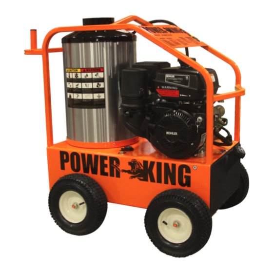
COMPONENT IDENTIFICATION Commercial Model: Gasoline Engine Coil Skin Burner Switch and Thermostat 10 Gallon Poly Fuel Tank Oil Fired Gas & Diesel • Rev. 4/7/2016... - Page 20 Direct Driven Pump Assembly: Safety Relief Valve Chemical Unloader Injector Burner Control Pressure Switch Temperature probe Water Inlet Water Pump Hot Water Outlet Quick Connector Oil Fired Gas & Diesel • Rev. 4/7/2016...
- Page 21 Hot Water Tank Interior (Top Cover Removed): Ceramic Coil Casing Coil Skin (outer Inner Steel stainless steel layer) Layer Pressure Wand Assembly: Spray Gun Nozzle Quick Coupler Trigger Black Nozzle for Wand Nozzles Downstream Chemical Application High Pressure Hose Oil Fired Gas & Diesel • Rev. 4/7/2016...
-
Page 22: Quick Diagnostics And Solutions Guide
QUICK DIAGNOSTICS AND SOLUTIONS GUIDE PUMP TYPE OF OIL EK Pump Hydraulic 68 (650ml) 30W SAE Non-Detergent GP Pump POSSIBLE CAUSES PROBLEM SOLUTIONS PRESSURE - Examine oil in pump to see if there is metal in oil. Metal in oil - If you find traces or pieces of metal, your pump has damaged components. - Page 23 PROBLEM POSSIBLE CAUSES SOLUTIONS BURNER - Make sure your battery is fully charged. - If the battery’s charge is not full, please Dead battery replace or re-charge your battery. - Make sure thermostat is connected properly. - If burner fan does not come on when you Damaged thermostat turn thermostat dial, replace thermostat.
-
Page 28: Manufacturer's Warranty
If you have any questions or comments regarding this warranty please call 1-800-344-3371. QVTOOLS, LLC POWERKING 2731 Crimson Canyon Dr Las Vegas, NV 89128 E-mail: sales@qvtools.com... -
Page 29: Service Manual
PowerKing Pressure Washers Service Manual This manual is intended for technical personnel to assist in the diagnosis and repair of issues with pressure washers. This manual is not intended for use by non-technical personnel. It is advised to always refer to competent technical personnel when repairs are advised to avoid equipment damage or potential personnel injury. - Page 30 POWER SYSTEM DIAGNOSTICS - Gas Motor Not Starting PROBLEM POSSIBLE CAUSE SOLUTION Fuel Check to see if proper fuel levels are maintained No ignition Check ignition by removing spark plug from cylinder. If electric start, try starting using the recoil starter. Gas motor not starting Electric Starter/Battery Recharge or replace battery.
- Page 31 FLUID SYSTEM DIAGNOSTICS - Flow and Pressure PROBLEM POSSIBLE CAUSE SOLUTION No power Make sure pump is operating. Check drive belts and couplings, make necessary adjustments. Trigger gun valve Check trigger gun, repair or replace. No water source Ensure water supply is not restricted and hoses are in good repair and not kinked. No Flow Clogged spray nozzle Check spray nozzle, repair or replace.
- Page 32 PROBLEM POSSIBLE CAUSE SOLUTION Nozzle must be properly sized for the rated flow and pressure. Reset unloader or pressure relief Small spray nozzle if nozzle size is changed. Check the pressure gauge using a properly calibrated pressure gauge on quick connects at the Excessive pressure Faulty pressure gauge equipment outlet.
- Page 33 FLUID SYSTEM DIAGNOSTICS - Unloader PROBLEM POSSIBLE CAUSE SOLUTION Isolate the flow problem. If it occurs before the unloader discharge point, check the piston Very low or no flow Unloader stuck in bypass assembly to see if it is fouled or stuck in bypass mode. Debris in unloader Take bottom nut off unloader, identify ball, spring and seat.
- Page 34 Unloader adjusted too low If the unloader is diverting flow to bypass it may be adjusted too low, readjust as necessary. Unloader (pressure) produces low flow and Spray nozzle to large Ensure the proper nozzle is installed on system. normal pressure Internal nozzle erosion The number of hours of usage can give you a clue to the extent of the ware.
- Page 35 FLUID SYSTEM DIAGNOSTICS - Leaking ANY LEAKS SHOULD BE REPAIRED ASAP TO PREVENT DAMAGE TO THE SYSTEM. PROBLEM POSSIBLE CAUSE SOLUTION From inlet Garden hose washer Ensure the washer is present and in good condition. From low pressure (inlet) Loose clamps or connections Low pressure line should be properly sealed on barb and tightly clamped.
- Page 36 FLUID SYSTEM DIAGNOSTICS - Trigger Gun/Spray Nozzle PROBLEM POSSIBLE CAUSE SOLUTION If water flows through discharge hose without gun, check trigger gun valve piston rod and Broken piston rod in trigger gun replace if necessary. No nozzle flow from nozzle when trigger depressed.
- Page 37 BOILER SYSTEM DIAGNOSTICS - Oil Burner Will Not Fire PROBLEM POSSIBLE CAUSE SOLUTION Not reaching rated pressure Not activating boiler controls Correct the fluid problem first - See fluid systems diagnostics flow Thermostat on low setting Thermostat set too low Set thermostat to an output temperature requiring heating.
- Page 38 PROBLEM POSSIBLE CAUSE SOLUTION Remove the solenoid cover and place blade of an insulated screwdriver in the coil with the Steady fuel flow at bleed Solenoid valve not energizing system operating in hot water mode. A good working solenoid will hold the screwdriver in the valve but none in solenoid.
- Page 39 BOILER SYSTEM DIAGNOSTICS -Gas Burner Will Not Fire PROBLEM POSSIBLE CAUSE SOLUTION No arc at the ignition pilot Spark gap incorrect Check the spark gap and reset if necessary. Check for air in the propane line. assembly Ignition module bad Check the ignition module and replace if necessary.
- Page 40 BOILER SYSTEM DIAGNOSTICS - Boiler Controls PROBLEM POSSIBLE CAUSE SOLUTION No voltage solenoid Boiler control or electrical problem A multimeter can be used to check continuity through controls and pinpoint the problem areas. Bad connection to solenoid coil Electrical connections to solenoid valve coil should be tight and not corroded. Solenoid coil does not Check to see if fuel solenoid will energize when the proper voltage is applied.
- Page 41 BOILER SYSTEM DIAGNOSTICS - Flow Switch - Optional PROBLEM POSSIBLE CAUSE SOLUTION Magnet fouled and will not move If magnet does not move freely within its housing, remove debris to unstick it. Reed switch activates when tested with external magnet Reed switch misadjusted To adjust it for the flow the system is producing, loosen the reed switch and move it in its Magnet is bad...
Need help?
Do you have a question about the POWER KING PK0702 and is the answer not in the manual?
Questions and answers