
Summary of Contents for Soil-Max Gold Digger Stealth ZD
- Page 1 Drainage Plow Manual Soil-Max, Inc. Precise, Progressive, Great Service 888-Soilmax (764-5629)
- Page 2 Have these thoroughly marked and maintain the recommended distance from these areas. Soil-Max is not liable for any damages or injury which may result from contact with any above ground or underground object. CALL (888) 258-0808...
- Page 3 Soil-Max Gold Digger Stealth ZD “How-To” Guide Thank you for purchasing the Soil-Max Gold Digger Stealth ZD. We know it is one of the most important tools you will ever have on the farm. Our purpose is to develop equipment that will make farmers profitable.
-
Page 4: Table Of Contents
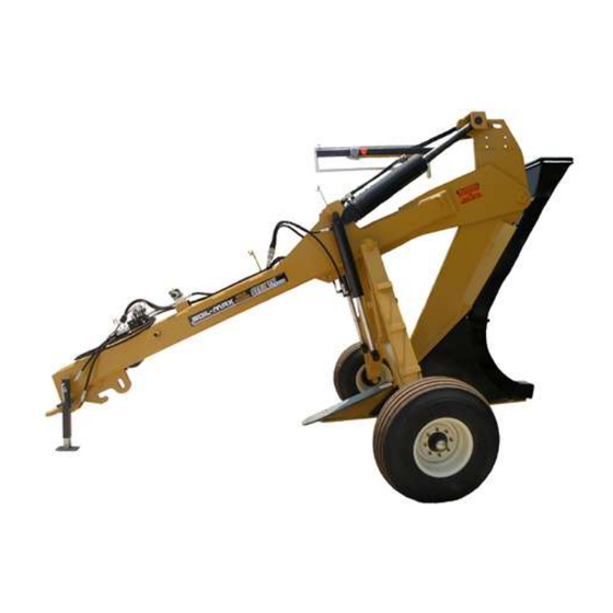
Table of Contents Plow “Parts Identification” Serial Number Identification “Which Tractor” to Use 3pt Plow Hookup and Geometry Toplink Cylinder Draft Control/Quick Hitch Hydrualic Hoses/Connections Waterlevel Pull-Type Plow Operation Drawbar Placement Down Pressure Manifold Electrical Schematics Boot Removal Shear Wear Tile Feeder Automatic Grade Control Hydraulic Schematics Manual Grade Control Hydraulic Schematics... - Page 5 Pull Type Parts Identification GPS Arm Mount Power Feeder Mount Tile Boot Rollers Depth Chain Water Level Proportional Valve Downpressure Valve Grease Daily Pull Hook Shear Heel Walking Tandems (Optional) Page 5...
- Page 6 3 Point Parts Identification GPS Arm Mount Depth Chain Water Level Power Feeder Mont Mount 7” Cylinders Funnel Rollers 6” Top Link Cylinder erer Proportional Valve Top Link Tower Boot Funnel Owner’s Manual Storage Heel Shear 3pt Stands Page 6...
- Page 7 Hydraulic Valve Parts Identification Down-Pressure Manifold Proportional Control Valve (Controls Plow Wheels) (Controls Plow Shank Pitch) See Index for Valve Schematic Diagrams Page 7...
-
Page 8: Serial Number Identification
Serial Number Identification Serial Number Plow Number The serial number will contain the plow number, date of manufacture and model information. You want to use the serial number for insurance purposes. My Serial Number: _______________________________________________________ Page 8... - Page 9 Tractor Selection The first decision to make before attaching the plow to a tractor is “which tractor do I use?” It is not necessarily true that the largest horsepower-rated tractor you have will work the best. You must take into consideration the weight of the tractor, how good the tires are, what type of tire (radial or bias) and the height of the tires.
- Page 10 3-Point ZD Plow Hookup and Geometry The 3-point comes equipped for Category III attachment. Attachment to a Category IV 3-Point hitch is possible with the use of CAT III to CAT IV bushings. All pins and hardware should come with the plow.
-
Page 11: Toplink Cylinder
Please use the top hole on the plow for attaching the top link if possible. However, be careful when lifting the plow the first time. On some tractors top link housing is directly beloow the stakc of hydraulic couplings and may hit part of the tractor when the plow is raised. Spacer blocks are available for John Deere 30 through 60 series tractors that may have this issue. - Page 12 Hydraulic Hoses The plow will come standard with pioneer hydraulic fittings. You will only need one set of hydraulic outlets if a plow control system such as laser or GPS is used. A separate outlet will be needed for the Make sure you connect to the tractor’s primary hydraulic remote.
-
Page 13: Waterlevel
Pull-Type Plow Operation Drawbar Placement When attaching a Gold Digger Stealth ZD Pull-Type plow to your tractor’s drawbar, please be sure that the drawbar is pulled in as close to the tractor as possible to avoid breaking or damaging the drawbar. - Page 14 Hydraulic Detente The wheels will not operate correctly if the tractor remote is detented (engaged) in the wrong direction. The down-pressure valve has TANK and PUMP marked on the ports in the front of the valve. The hose connected to the PUMP port should be stiff with pressure when detented (engaged) correctly. Hydraulic Flow Only Goes One Way Switchbox Instructions The instructions in this section pertain to how you operate the wheels on a pull-type Gold Digger plow.
-
Page 15: Down Pressure Manifold Electrical Schematics
Down Pressure Manifold Electrical Schematics Note: The position of the wires to the solenoids on the Down Pressure Manifold is very important. With incorrect wire placement, malfunction of the manifold will occur and potential injury. Please take care when removing, cleaning, or replacing wire connections. Page 15... -
Page 16: Boot Removal
Boot Removal Often during the course of an installation, different boot sizes will be needed. Changing the boot is easily done. First remove the fastener marked 1 and remove the funnel. Remove fastener marked 2 and the bottom portion of the boot will come off in two pieces. -
Page 17: Tile Feeder
Tile Feeder (Optional) The optional tile feeder is a great addition to any plow. It is not required but is a great reassurance of tile quality. The tile feeder simply pushes on the tile to ensure no stretch is occurring. Hydraulic fluid direction is important to correct operation. -
Page 18: Automatic Grade Control Hydraulic Schematics
Automatic Grade Control Plow Hydraulic Schematics “T” Stands for “TANK”. This is the port through which oil returns to the reservoir. “P” Stands for “PRESSURE” or “PUMP”. This is the port thorough which pressurized oil is sent to the plow. Page 18... -
Page 19: Manual Grade Control Hydraulic Schematics
Manual Grade Control Plow Hydraulic Schematics “T” Stands for “TANK”. This is the port through which oil returns to the reservoir. “P” Stands for “PRESSURE” or “PUMP”. This is the port thorough which pressurized oil is sent to the plow. Page 19... -
Page 20: Electronics Hookup
Electronics Hookup Intellislope GPS Control System: If you purchased the Intellislope GPS plow control system please refer to that systems manual for this section. To learn more about the Intellislope you can visit: www.intellislope.com or call us toll free at: 888-SOILMAX and select Sales (option one). - Page 21 Wiring Schematic For TopCon Laser Systems On 3pt Gold Digger Wiring Schematic For TopCon Laser Systems On Pull Type Gold Digger Page 21...
-
Page 22: Topcon Laser System Initial Setup
TopCon Laser System Initial Setup: This is a very important setup procedure to run when setting the control system up on any other tractor. This setup is done using the Topcon RD2 control box (in cab unit), TopCon LSB2 receiver (on plow unit), and the RL-100 1S laser transmitter on the tripod. - Page 23 This setup procedure is outlined in the LSB2 laser receiver’s manual. This setup is the key to controlling grade smoothly. Please contact Soil-Max if you have any questions about this procedure. On a single grade TopCon transmitter, the words “TOPCON” should face the direction of travel up the grade.
- Page 24 Wiring Schematic For Apache Laser Systems On 3pt Gold Digger Wiring Schematic For Apache Laser Systems On Pull Type Gold Digger Page 24...
-
Page 25: Apache Laser System Initial Setup
Apache Laser System Initial Setup 1. LED grade display 2. Power ON / OFF push switch 3. Power ON indicator 4. Automatic / Manual toggle switch 5. Automatic ON indicator 6. Manual ON indicator 7. Raise / Lower toggle switch 8. - Page 26 Operation Switches under Access Panel (#9 pg22) 10. Rotary switch - On-Grade Deadband selections (Default setting is "8".) 11. Dip Switch 4-way - Performance selections (Default setting is all in the OFF position.) 12. Rotary switch - Valve gain (speed) (Default setting is "8".) Installation Switches: 13.
- Page 27 Apache System Initial Setup: This is a very important setup procedure to run when transferring the control system onto any other tractor. This setup is done using the Apache C26 control box (in cab unit), Apache receiver (on plow unit), and the Topcon RL-100 1S laser transmitter on the tripod on the fastest rotation setting. Find the Valve Set Up (14) dip switches shown in the diagram on the page prior under the access panel.
- Page 28 Page 27...
- Page 29 The higher the number, the faster the plow will move. It is good to keep in mind that the plow naturally will have suction to go down. The Raise minimum correction should be somewhat higher than the lower minimum correction. RAISE Minimum Correction: (switch 1 in ON position) 1.
-
Page 30: Incorporating S Second Pull Tractor
Using the Gold Digger in the Field Tile runs, using the Gold Digger ZD, will need to be started at the desired tile depth in a “start hole” or if possible from a drainage ditch. However, is easier to start from a hole. You will always install the tile up slope from the start hole. -
Page 31: Manual Grade Control
Manual Grade Control: This method is most commonly used where there is sufficient slope (usually >1% and no humps or valleys) and a laser would not necessarily be needed. Once you have started the tile run, you will need to make sure the water level is in the green graduated area. This means you are tiling at a positive slope. -
Page 32: Designing Tile Systems
Designing Tile Systems: Designing your tile system may be the most difficult part of tiling. The general layout may not be difficult but, you will need to make sure you are able to put the entire tile in at a depth where you have sufficient coverage everywhere and not have to go too deep to keep good coverage everywhere. - Page 33 We would be glad to try to answer any questions you might have or refer you to someone who could answer your questions. Many States also have drainage guides available at extension offices that explain in detail subsurface drainage along with tables of drainage coefficients, recommended tile sizes, grades, and spacing of drainage systems.
-
Page 34: Using A Laser-Determining Grade & Coverage
Using a Laser-Determining Grade and Coverage If you purchased a laser with your plow, you can use it to determine the grade of each tile run as well as the depth the tile will be at intervals within the field. 1) To determine the grade of a particular tile run, set the laser on its tripod about half-way up the grade. - Page 35 The depth of tile was calculated by taking the depth of the tile at the first reading (36 inches) and adding or subtracting the amount of ground cover gained or lost gained or lost by the height of the land at each reading, then subtract the depth lost by the tile sloping up.
- Page 36 Tile Grade Situations: Standard Grade Calculation Calculating for a desired grade with a known starting and ending depth. Determining the plow depth at a known distance. Calculating depth needed to cover a reverse grade (going over hump to low spot). Calculating Starting Depth Page 35...
-
Page 37: Frequently Asked Questions
Q: How deep of a frost layer can I tile through with my Gold Digger Stealth ZD tile plow? A: Soil-Max does not recommend tiling in anymore than 4” of frozen top soil. When the topsoil is frozen it can damage boots and it decreases the amount of topsoil cover that falls in on top or your tile. -
Page 38: Index
Index Apache Laser System Initial Setup Incorporating s Second Pull Tractor Automatic Grade Control Automatic Grade Control Hydraulic Schematics Manual Grade Control Manual Grade Control Hydraulic Schematics Boot Removal Plow “Parts Identification” Designing Tile Systems Pre Ripping Down Pressure Manifold Electrical Schematics Pull-Type Plow Operation Draft Control/Quick Hitch...
Need help?
Do you have a question about the Gold Digger Stealth ZD and is the answer not in the manual?
Questions and answers