Table of Contents
Advertisement
Quick Links
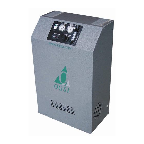
OG-15 and OG-20
Oxygen Generators
Installation, Operation and
Maintenance Manual
Oxygen Generating Systems Intl. (OGSI)
Division of Audubon Machinery Corporation
814 Wurlitzer Drive, North Tonawanda, New York 14120USA
Tel: (716) 564-5165 Toll Free: (800) 414-6474 Fax: (716) 564-5173
E-mail: ogsimail@ogsi.com
Website: www.ogsi.com
Part # 9000000-005
US $25.00
Effective 07/2014
Advertisement
Table of Contents

Related Manuals for OGSI OG-15

Summary of Contents for OGSI OG-15
- Page 1 OG-15 and OG-20 Oxygen Generators Installation, Operation and Maintenance Manual Oxygen Generating Systems Intl. (OGSI) Division of Audubon Machinery Corporation 814 Wurlitzer Drive, North Tonawanda, New York 14120USA Tel: (716) 564-5165 Toll Free: (800) 414-6474 Fax: (716) 564-5173 E-mail: ogsimail@ogsi.com Website: www.ogsi.com...
- Page 2 Page left intentionally blank...
-
Page 3: Table Of Contents
Table of Contents Topic Page Number Using this Manual Initial Inspection Warranty Information and Liabilities Safety Guidelines Unpacking Operating 7-32 Product Information Features and Applications PSA Technology Components Process Flow Description Specifications Performance Curve Safety Precautions Pre –... - Page 4 ©2014, OGSI. All rights reserved. OGSI is a registered trademark. This publication may not be reproduced in part or whole without written permission of OGSI.
-
Page 5: Using This Manual
Using this Manual This manual is intended as a guide for operators of OGSI Oxygen Generators and Oxygen Generating Systems. It includes information on our warranty policy, features, functions, applications, proper set-up and installation, operation and preventive maintenance of our products. -
Page 6: Initial Inspection
OGSI shipping terms are Free On Board (FOB), North Tonawanda, NY USA. This means that once the equipment leaves our dock you are the owner of it. OGSI has no legal claim to make against any shipping company for damage. -
Page 7: Warranty Information And Liabilities
(1) year from the date of delivery to the original user. OGSI will pay for shipping the Products to the original user as well as returning damaged/defective Products to OGSI. - Page 8 Products will be billed and due on receipt. Note: The warranties of OGSI as set forth herein shall also become null, void and not binding on OGSI if a defect or malfunction occurs in the Products or any part of the Products as a result of:...
-
Page 9: Safety Guidelines
Safety Guidelines Unpacking DDITIONAL PACKAGING MATERIAL INSIDE THE UNIT MUST BE REMOVED AND THE AIR INLET FILTER MUST BE INSTALLED PRIOR TO OPERATING THE OXYGEN GENERATOR Ensure that the unit is NOT connected to an electrical outlet. Remove the six (6) screws with nylon washers located on the front and both sides of the unit. ... -
Page 10: Operating
Operating OGSI Oxygen Generators are self-contained systems for the production of high purity oxygen. Although oxygen itself is not combustible, it can be very dangerous. It greatly accelerates the burning of combustible materials. Precautions should be taken to avoid a fire in the area of the oxygen generator. -
Page 11: Product Information
Built on a powder coated steel chassis, its anodized aluminum sieve beds are fitted with custom aluminum end caps for years of reliable service. Portable The OG-15 weighs 65 lb (29 kg) without cover and the OG-20 weighs 67 lb (30 kg) without cover. These units are industrial strength oxygen generators. - Page 12 Applications The OG-15 and OG-20 can be used in various applications. A few examples are given below. Hyperbaric Oxygen Therapy (HBOT) Fish Farming and Aquaculture Ornamental Glass Manufacturing Jewelry Manufacturing Bottled Water Manufacturing Waste and Water Treatment Effective 07/2014...
-
Page 13: Psa Technology
Pressure Swing Adsorption (PSA) Technology An OGSI Oxygen Generator is an on-site oxygen generating machine capable of producing oxygen on demand in accordance with your requirements. In effect, it separates the oxygen (21%) from the air it is provided and returns the nitrogen (78%) to the atmosphere through a waste gas muffler. -
Page 14: Components
External Components Front View 1. Air Pressure Gauge 2. ON/OFF Power Switch 3. Hours Meter 4. Anti-vibration Feet (Optional) 5. Oxygen Pressure Gauge 6. Oxygen Flow Meter 7. Oxygen Pressure Regulator Effective 07/2014... - Page 15 Control Panel (Magnified View) 1. ON/OFF Power Switch 2. Model Number 3. Oxygen Flow Meter Knob 4. Oxygen Pressure Regulator Knob Effective 07/2014...
- Page 16 Side Views Left Right 1. Vent Hole (8” minimum clearance) 1. Oxygen Outlet 2. Cabinet 2. Cabinet 3. Reset Button 3. Vent Hole (8” minimum clearance) 4. Voltage Label Effective 07/2014...
- Page 17 This gauge indicates the pressure at which the oxygen is being delivered. The flow meter is calibrated at 12 psi (0.83 bar) for OG-15 and 20 psi (1.4 Oxygen Pressure Gauge bar) for OG-20 and the pressure must be adjusted to this level when reading the flow meter.
- Page 18 Internal Components (OG-15) Front View 1. Control Panel 2. Terminal Assembly Strip 3. Sieve Bed 4. Heat Exchanger 5. Air Compressor 6. Circuit Board 7. Pre-filter 8. Valve Block (115 VAC or 230 VAC) 9. Inlet Air Filter 10. Safety Relief Valve (55 psi)
- Page 19 Back View (Standard) 1. Oxygen Receiver Tank 2. Cooling Fan (115 VAC or 230 VAC) 3. Capacitor 4. Power Cord 5. Vent Holes 6. Purge Loop 7. Check Valves 8. Exhaust Muffler 9. Serial Number Locator (Not Visible) Effective 07/2014...
- Page 20 Back View (Quiet Muffler Option) 1. Oxygen Receiver Tank 2. ½” Female Elbow 3. ¼” Foam Filter 4. Exhaust Muffler 5. ½”x ¼” Reducing Nipple Effective 07/2014...
- Page 21 Internal Components (OG-15E Compressor-less) Front View 1. Terminal Assembly Strip 2. Sieve Bed 3. Regulator Adjustment Knob 4. Inlet Pressure Gauge 5. Filter Regulator 6. Inlet Check Valve 7. Compressed Air Inlet 8. Control Panel 9. Circuit Board 10. Safety Relief Valve 11.
- Page 22 Back View 1. Oxygen Receiver Tank 2. Cooling Fan (115 VAC or 230 VAC) 3. Check Valves 4. Exhaust Muffler 5. Power Cord Effective 07/2014...
- Page 23 Internal Components (OG-20) Front View 1. Control Panel 2. Terminal Assembly Strip 3. Sieve Bed 4. Heat Exchanger 5. Air Compressor 6. Circuit Board 7. Sieve Bed 8. Pre-Filter 9. Valve Block (115 VAC or 230 VAC) 10. Inlet Air Filter 11.
- Page 24 Back View 1. Oxygen Receiver Tank 2. Cooling Fan (115 VAC or 230 VAC) 3. Capacitor 4. Power Cord 5. Vent Holes 6. Purge Loop 7. Check Valves 8. Exhaust Muffler 9. Serial Number Locator (Not Visible) Effective 07/2014...
- Page 25 Internal Components (OG-20E Compressor-less) Front View 1. Terminal Assembly Strip 2. Sieve Bed 3. Regulator Adjustment Knob 4. Inlet Pressure Gauge 5. Filter Regulator 6. Inlet Check Valve 7. Compressed Air Inlet 8. Control Panel 9. Circuit Board 10. Safety Relief Valve (55 psi) 11.
- Page 26 Back View 1. Oxygen Receiver Tank 2. Cooling Fan (115 VAC or 230 VAC) 3. Check Valves 4. Exhaust Muffler 5. Power Cord Effective 07/2014...
- Page 27 The exhaust muffler is used to silence the exhaust noise that occurs as a result of the sieve beds rapidly depressurizing to atmospheric pressure, releasing nitrogen. For Exhaust Muffler installations where a lower noise level is required, OGSI offers an optional alternative muffler system that can decrease the emitted noise even further. Air Regulator The air regulator controls the air pressure going into valve block.
- Page 28 Process Flow Schematic: OG-15 and OG-20 Effective 07/2014...
- Page 29 Process Flow Schematic: OG-15E and OG-20E (Compressor-less) Effective 07/2014...
-
Page 30: Process Flow Description
Drawings. As you can see, once the incoming air is filtered and compressed in the OG-15/OG-20 unit or regulated to the proper pressure in the OG-15E/OG-20E (Compressor-less) unit, it is directed into one of the two sieve beds. As the air enters the bed, the nitrogen is adsorbed by the sieve and the oxygen passes through as product gas to the storage tank. -
Page 31: Specifications
Unit Specifications: OG-15 Performance 15 SCFH @ 12 psi Oxygen Volume 7 LPM or 0.4 Nm /h @ 0.83 bar Oxygen Pressure OG-15 1 – 12 psi (0.83 bar) OG-15E (Compressor-less) 1 – 12 psi (0.83 bar) Oxygen Purity 93% (±... - Page 32 Continued from Page 27 Power Requirement OG-15 Standard (Domestic) 115 VAC, 60 Hz, Single Phase 6.0 A Optional (International) 230 VAC, 50/60 Hz, Single Phase, 3A OG-15E (Compressor-less) Standard (Domestic) 115 VAC, 60 Hz, Single Phase, 0.2 A ...
- Page 33 Unit Specifications: OG-20 Performance 20 SCFH @ 20 psi (1.4 bar) Oxygen Volume 10 LPM or 0.5 Nm /h @ 1.4 bar Oxygen Pressure OG-20 1 – 20 psi (1.4 bar) OG-20E(Compressor-less) 1 – 20 psi (1.4 bar) Oxygen Purity 93% (±...
- Page 34 Continued from Page 29 Power Requirement OG-20 Standard (Domestic) 115 VAC, 60 Hz, Single Phase 6.0 A Optional (International) 230 VAC, 50/60 Hz, Single Phase, 3.0 A OG-20E(Compressor-less) Standard (Domestic) 115 VAC, 60 Hz, Single Phase, 0.2 A ...
-
Page 35: Performance Curve
Performance Curves Oxygen Purity vs. Flow OG-15 OXYGEN PURITY (± 3%) OXYGEN FLOW RATE (SCFH) OG-15 E Compressor-less OXYGEN PURITY (± 3%) OXYGEN FLOW RATE (SCFH) Effective 07/2014... - Page 36 OG-20 OXYGEN PURITY (± 3%) OXYGEN FLOW RATE (SCFH) OG-20 E Compressor-less OXYGEN PURITY (± 3%) OXYGEN FLOW RATE (SCFH) NOTE: SCFH (Standard Cubic Foot per Hour) gas measured at 1 atmosphere and 70 °F and 0% humidity. Effective 07/2014...
-
Page 37: Safety Precautions
Safety Precautions It is very important that you read the precautions below and make yourself aware of the hazards of oxygen in general. While it can be handled and used very safely, it can also be mishandled or applied incorrectly causing dangerous situations. Oxygen is a fire hazard. -
Page 38: Pre-Installation
2) Space Available for the OG-15/OG-20: If the OG-15/OG-20 unit is going to be set up in a room that is small, (less than 1000 ft or 28.3 m ), that room should be well ventilated (at least 5 air changes in the room per hour). -
Page 39: Required Operating Conditions
This equates to approximately 700 W of power. It is required that a 10 A circuit be dedicated to each OG-15/OG-20 unit. Additionally, the unit must be connected to this circuit using only the supplied power cord, and without the use of additional extension cords. -
Page 40: Set-Up And Installation
10 LPM flow for OG-15 and OG-20 respectively. The oxygen pressure gauge should read 12 psi (0.83 bar) or 20 psi (1.4 bar) for OG-15 and OG-20 respectively. If it does not, turn the oxygen regulator either clockwise to increase the pressure or counter-clockwise to decrease it until it reaches 12 psi (0.83 bar) or 20 psi (1.4 bar) for OG-15 and OG-20 respectively. -
Page 41: Operating Instructions
After connecting it to an electrical outlet and pushing the switch on the machine to the ON position, wait for 2 minutes for the unit to come up to maximum purity. The oxygen delivery pressure should be set to 12 psi (0.83 bar) for OG-15 and 20 psi (1.4 bar) for OG-20. -
Page 42: Troubleshooting Guide
Troubleshooting Guide Problem Sign Cause Solution Contaminated sieve Repack the sieve beds. Dusting of Sieve Beds White powder visible Moisture in air Clean valves and mufflers. in the machine or very Make sure dry air is being high air pressure levels fed to the machine. -
Page 43: Preventive Maintenance
Replacement in the field is possible, but returning the unit to OGSI or an authorized service center is recommended. Valve Replacements: The best method to address this issue is to return the unit to OGSI or to an authorized service center for repair. Effective 07/2014... -
Page 44: Technical Service Assistance
Technical service personnel are available from 8:00 AM to5:00 PM EST (GMT - 5). We also have a list of Distributors and Authorized Service Agents available upon request. Customer Satisfaction Survey Help us serve you better. Please take our Customer Satisfaction Survey at www.ogsi.com Effective 07/2014... - Page 45 Appendix Effective 07/2014...
- Page 46 Page left intentionally blank...
-
Page 47: Certificate Of Compliance
OG-15/OG-20 CERTIFICATE OF COMPLIANCE GENERATOR/TESTING INFORMATION Technician_________________________ Serial No. /Mod______________________ Date___/___/___ Hours____ Purity____% Regulated Air Pressure: Low____ High____ Outlet Pressure_____ psi Flow Meter Setting_____ SCFH Voltage 110V □ 220V □ Temperature_____ °F Humidity_____% QUALITY CONTROL INFORMATION PASSED PASSED Flow Meter & Fittings Regulator &... - Page 48 Page left intentionally blank...
-
Page 49: Spare Parts List
Spare Parts List OG-15 PART NAME PART NUMBER QUANTITY Strain Relief for Power Cord 1820018-001 Reset Button 1830002-001 ON/OFF Lighted Switch 1840001-004 Timer 115 VAC/230 VAC 1850001-001 Hours Meter 115 VAC 1870002-002 Hours Meter 230 VAC 1870002-003 Valve Wire Harness (each) 115 VAC... - Page 50 OG-20 PART NAME PART NUMBER QUANTITY Strain Relief for Power Cord 1820018-001 Reset Button 1830002-001 ON/OFF Lighted Switch 1840001-004 Timer 115 VAC/230 VAC 1850001-002 Hours Meter 115 VAC 1870002-002 Hours Meter 230 VAC 1870002-003 Valve Wire Harness (each) 115 VAC 1880011-002 Valve Wire Harness (each) 230 VAC 1880011-003...
-
Page 51: Oxygen Cleaning Procedure
This procedure sets forth the cleaning requirements for parts that are used in the construction of OGSI oxygen systems and are in the gaseous oxygen product stream, including but not limited to valves, tubing, fittings, manifolds and pipes. This procedure represents the method for cleaning OGSI oxygen service equipment. - Page 52 Process Flow Chart The flow chart below describes oxygen cleaning and parts handling process. Rinse Purge and dry Parts Received and Initial Inspection Upon determining which parts need to be cleaned, the technician needs to perform an initial visual inspection (under white light). Check for the presence of visible residue on the parts including but not limited to oil, grease, dirt, dust, rust, weld slag or pre-existing thread sealant among others.
- Page 53 Inspection Upon completion of the final rinse cycle, all parts should be removed from the parts washing machine and visually inspected with both a bright white light and an ultraviolet (“black”) light for any residual contamination. The item shall be observed to confirm the absence of any contaminants including any oil, grease, detergent, moisture, lint, or other foreign materials.
- Page 54 References The following publications were referenced in the creation of this document. CGA G-4.1-2009, Cleaning Equipment for Oxygen Service, Compressed Gas Association, Inc., 4221 Walney Road, 5 Floor, Chantilly, VA 20151. www.cganet.com Oxygen Cleaning Procedure Rev. L (8/05), RIX Industries, Inc., 4900 Industrial Way, Benicia, CA 94510.
-
Page 55: Air Changes By Room Size
OG-750 22.5 OG-1000 OG-1250 OG-1500 CFP- 15+/15M MOGS-100 Notes: 1. NR means that the models indicated are not recommended for rooms of this size. 2. For air changes requirements for models OG-2000 and above, please contact OGSI. Effective 07/2014 VIII... -
Page 56: Units Of Measurements
Units of Measurement U.S. Pound Horsepower Pound-force per Square Inch Kilowatt Kilowatt hour Cubic Feet Volts Alternating Current Hertz SCFH Standard Cubic Foot per Hour SCFM Standard Cubic Foot per Minute Liter Per Minute 1 bar 1.45 x 10 Decibel (A scale) Ampere Watt °C... -
Page 57: Maintenance Log
Maintenance Log Authorized Service Date Part Reason for Maintenance Technician Signature Effective 07/2014...
Need help?
Do you have a question about the OG-15 and is the answer not in the manual?
Questions and answers