Advertisement
Quick Links
© Gooligum Electronics 2015
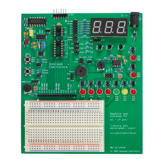
Baseline and Mid-Range PIC (6 – 14 pin)
This PIC development board is designed as a training environment specifically for use with the
introductory Gooligum baseline, mid-range and enhanced mid-range PIC tutorials
The tutorials were originally written for Microchip's Low Pin Count Demo Board, which supports 8-, 14-
and 20-pin PICs, can be used easily with a PICkit 2 or PICkit 3 programmer, and provides four LEDs, a
pushbutton switch and a potentiometer. As such, it's a good, simple introductory board. However, it does
not support the 6-pin 10F PICs and its LEDs cannot be used directly with 8-pin PICs.
More significantly, many of the Gooligum baseline and mid-range lessons require the use of parts not
included on that board, such as photocells, crystal-driven oscillator circuits, and 7-segment LED displays.
Although it is possible to build all of these circuits on a breadboard, connected to the Low Pin Count
Demo Board, it is a little cumbersome – especially for some of the more complex circuits.
This training board was developed to make it easy to follow the Gooligum baseline, mid-range and
introductory enhanced mid-range lessons. It works with a PICkit 2 or PICkit 3 programmer, and supports
all 8- and 14-pin baseline, mid-range and enhanced mid-range PICs, as well as all 6-pin 10F devices (in an
8-pin DIP package). It is fully configurable using the provided jumpers, and comes with all of the
hardware needed for every introductory lesson, including all the required PICs.
It features:
Support for all 6-pin, 8-pin and 14-pin baseline, mid-range and enhanced mid-range PICs
(all 10F, 12F and 14-pin 16F devices)
2 × pushbuttons (including
o optional external pull-up resistor on each pushbutton
9 × LEDs
o an LED is available on each 6-pin and 8-pin PIC output pin, plus pins RC0 – RC3
3 × 7-segment LED displays
o configurable as a single digit or multiplexed digits
External 32.768 kHz oscillator
o can be configured to drive processor clock, Timer0 or Timer1
4 MHz resonator, 32.768 kHz crystal and resistor/capacitor for use with processor oscillator
o 32.768 kHz crystal also available for Timer1 oscillator
Potentiometer and 2 × photocells for use as analog inputs in comparator and ADC lessons
Variable frequency oscillator for frequency and pulse width measurement lessons
Piezo sounder, to demonstrate PWM outputs
Standard ICSP connector for use with PICkit 2 or PICkit 3 programmer
1
All baseline, mid-range, and introductory enhanced mid-range assembler and C lessons
Baseline and mid-range PIC training and dev board operation guide
Training and Development Board
Construction and Operation Guide
)
MCLR
www.gooligum.com.au
1
.
Page 1
Advertisement

Summary of Contents for Gooligum Electronics Baseline and Mid-Range PIC
- Page 1 Piezo sounder, to demonstrate PWM outputs Standard ICSP connector for use with PICkit 2 or PICkit 3 programmer All baseline, mid-range, and introductory enhanced mid-range assembler and C lessons Baseline and mid-range PIC training and dev board operation guide Page 1...
- Page 2 PCB. See the parts list, in appendix B, for details. Construction is straight-forward, only needing basic soldering skills. All components are through-hole, and a component overlay (as shown below) is provided on the PCB. Baseline and mid-range PIC training and dev board operation guide Page 2...
- Page 3 The header shunts should also be put aside to use later, when you configure the training board for each lesson. Baseline and mid-range PIC training and dev board operation guide Page 3...
-
Page 4: Operation
Although PIC10Fs are 6-pin devices, only those supplied in 8-pin DIP packages can be used (directly) with this training board. Only 6 pins of the 8-pin package are available for use; the PIC10F is still a 6-pin device. Baseline and mid-range PIC training and dev board operation guide Page 4... - Page 5 PICs (mostly ‘LF’ variants) will only tolerate a supply of up to 3.6 V- you should limit your external power supply to no more than 4 V if you are using one of these devices Baseline and mid-range PIC training and dev board operation guide Page 5...
- Page 6 150 Hz to 10 kHz, using trimpot RP1. The digital form of this signal can be connected to either the Timer 1 gate input, , or the capture input pin, CCP1, using jumper block JP26. Baseline and mid-range PIC training and dev board operation guide Page 6...
-
Page 7: Pin Description
GP3 / RA3 / RB3 GP0 / RA0 / RB0 GP1 / RA1 / RB1 GP2 / RA2 / RB2 Variable frequency (150 – 10000 Hz) digital signal Power (+V) Ground Baseline and mid-range PIC training and dev board operation guide Page 7... -
Page 8: Jumper Summary
Connects OSC1 to 32.768 kHz external clock (EC mode) Connects OSC2 to 4.00 MHz ceramic resonator (XT oscillator) JP21 Connects OSC2 to 32.768 kHz watch crystal (LP oscillator) Baseline and mid-range PIC training and dev board operation guide Page 8... - Page 9 Connects LDR2 to CIN- / C1IN- Connects digital variable frequency signal to CCP1 JP26 Connects digital variable frequency signal to JP27 Connects sawtooth variable frequency signal to C2IN+ Baseline and mid-range PIC training and dev board operation guide Page 9...
-
Page 10: Appendix A - Jumper Settings
2 of JP20, connecting one side of a 32.768 kHz watch crystal to OSC1 position 2 of JP21, connecting the other side of the watch crystal to OSC2 Every other jumper should remain open. Baseline and mid-range PIC training and dev board operation guide Page 10... - Page 11 ● 2-3 2 ● ● ● ● all 1 2-3 ● ● all 1 2-3 ● ● ● all 1 2-3 ● ● all 1 2-3 ● ● Baseline and mid-range PIC training and dev board operation guide Page 11...
- Page 12 ● ● ● ● ● ● ● ● ● ● ● ● ● 2-3 2 ● ● ● ● ● ● ● ● ● ● ● ● ● Baseline and mid-range PIC training and dev board operation guide Page 12...
- Page 13 ● ● ● ● ● ● ● ● ● ● ● ● ● ● ● ● ● ● ● ● ● ● ● ● ● ● ● ● Baseline and mid-range PIC training and dev board operation guide Page 13...
- Page 14 ● ● ● ● 2 1-2 ● 2 1-2 2 1-2 2 1-2 ● ● 2 1-2 2 1-2 2 1-2 ● ● ● 1 2-3 ● ● Baseline and mid-range PIC training and dev board operation guide Page 14...
- Page 15 9 10 11 12 13 14 15 16 17 18 19 20 21 22 23 24 25 26 27 1-2 1-2 ● 1 2-3 ● ● ● 1 2-3 ● ● ● Baseline and mid-range PIC training and dev board operation guide Page 15...
- Page 16 ● ● ● ● ● ● ● ● ● ● ● ● ● ● ● ● 2-3 3 ● ● ● ● 2-3 3 ● ● ● ● Baseline and mid-range PIC training and dev board operation guide Page 16...
- Page 17 2 1-2 2 1-2 ● ● ● 1 2-3 ● ● 1-2 1-2 ● 1 2-3 ● ● ● 1 2-3 ● ● ● 1 2-3 ● ● ● Baseline and mid-range PIC training and dev board operation guide Page 17...
- Page 18 1 2-3 ● ● ● all 1 2-3 ● ● all 1 2-3 ● ● all 2 1-2 all 2 1-2 all 2 1-2 ● ● ● Baseline and mid-range PIC training and dev board operation guide Page 18...
- Page 19 ● ● ● ● ● all 1 2-3 ● ● ● all 1 2-3 ● ● all 2 1-2 all 2 1-2 all 2 1-2 ● ● ● Baseline and mid-range PIC training and dev board operation guide Page 19...
- Page 20 ● ● ● ● ● ● ● ● ● ● ● ● ● ● ● ● ● ● ● ● ● ● ● ● ● ● ● ● Baseline and mid-range PIC training and dev board operation guide Page 20...
- Page 21 2 1-2 all 2 1-2 all 2 1-2 ● all 2 1-2 all 2 1-2 all 2 1-2 ● ● ● all 1 2-3 ● ● ● 1-2 1-2 Baseline and mid-range PIC training and dev board operation guide Page 21...
- Page 22 ● ● ● ● ● ● ● ● ● ● ● ● ● ● ● ● ● ● ● all 1 1-2 all 1 2-3 ● ● ● Baseline and mid-range PIC training and dev board operation guide Page 22...
- Page 23 2 1-2 all 2 1-2 all 2 1-2 ● all 2 1-2 all 2 1-2 all 2 1-2 ● ● ● all 1 2-3 ● ● ● 1-2 1-2 Baseline and mid-range PIC training and dev board operation guide Page 23...
-
Page 24: Appendix B - Parts List
7-segment LED displays (10-pin DIP, e.g. Kingbright SC52-11SRWA) NE555 timer (bipolar) 74HCU04N hex inverter (unbuffered) 5 mm LEDs (red, green or yellow: normal intensity, diffused) CDS photocells (LDRs), 20-60 kΩ when illuminated Baseline and mid-range PIC training and dev board operation guide Page 24... - Page 25 14-pin DIP IC socket 6 mm PCB-mount tactile pushbutton switches Accessories Description self-adhesive rubber feet 2” × 3” solderless breadboard 22 AWG solid-core insulated jumper wire header shunts Baseline and mid-range PIC training and dev board operation guide Page 25...
- Page 26 10 kΩ 5% 1/4W resistors 22 kΩ 5% 1/4W resistors 100 kΩ 5% 1/4W resistors 1N4148 diodes 74HC14N hex Schmitt-trigger inverter CDS photocells (LDRs), 20-60 kΩ when illuminated PCB-mount pushbutton switch Baseline and mid-range PIC training and dev board operation guide Page 26...
- Page 27 SN754410 (or L293D) quad half-H driver with internal clamp diodes MDN3BL3CSAS (or similar) 2 - 5 V brushed DC motor with wire leads 1N400x series rectifier diode 220 Ω 5% 1/4W resistors 10 kΩ 5% 1/4W resistors Baseline and mid-range PIC training and dev board operation guide Page 27...
- Page 28 © Gooligum Electronics 2015 www.gooligum.com.au Appendix C – Schematics Sheet 1: Main Baseline and mid-range PIC training and dev board operation guide Page 28...
- Page 29 © Gooligum Electronics 2015 www.gooligum.com.au Sheet 2: Digital I/O Baseline and mid-range PIC training and dev board operation guide Page 29...
- Page 30 © Gooligum Electronics 2015 www.gooligum.com.au Sheet 3: Oscillator section Baseline and mid-range PIC training and dev board operation guide Page 30...
- Page 31 © Gooligum Electronics 2015 www.gooligum.com.au Sheet 4: Analog Baseline and mid-range PIC training and dev board operation guide Page 31...
Need help?
Do you have a question about the Baseline and Mid-Range PIC and is the answer not in the manual?
Questions and answers