Table of Contents
Advertisement
Quick Links
Advertisement
Table of Contents

Summary of Contents for Techmach AWG5000
-
Page 3: Table Of Contents
Tale of Contents Quick instructions for ultrasonic sensor or infrared sensor........Inside Front Photoelectric sensor Techmach LS80 Manual............OUTside Front Safety and Warning........................2 Introduction..........................5 Technical specification......................7 Installation and Adjustment.......................9 Operation............................13 ........................15 AW5000 control enclosure Troubleshooting..........................22 Maintenance..........................24 Shipping and Storage........................24 Warranty Policy & server after sale..................25 Appendix I....................................26... -
Page 4: Safety And Warning
Safety and Warning Make sure carefully read this manual before your installing, wiring, starting, operating or making practices while operating and maintaining this unit. Please operate the web guiding control system with necessary skill and complete awareness of the Safety and Warning, make sure not operated by unqualified person. We used signal words WARNING and CAUTION to indicate Hazard seriousness levels asfollows: WARNING: is used to indicate the presence of a hazard, which can cause severe personal injury, death, or substantial property damage if the warning is ignored. - Page 5 2.Read the fallowing carefully to defend against the fire: Make sure not use any tinder to install switch power or web guide control enclosure, otherwise a fire may be caused. Make sure switching off the power supply first while any faults happens with the switch power or web guide control enclosure.
- Page 6 Caution: Linear Actuator and the sensor should be fastened on the mechanism firmly, otherwise will effect the accuracy, even caused serious damage to this device. As for installation of linear actuator, please distinguish the position between R end (fixed) and F end (unfixed), otherwise serious damage to this mechanism will be caused, even rejected.
-
Page 7: Introduction
This mechanism should be installed, activated and operated by qualified person. Remove manually allowed. AWG5000 is a high performance web guiding system with high accuracy, stability and reliability and quite simple to install or operate. This system is compatible with Techmach’s compensated ultrasonic edge detectors, compensated IR edge detectors and Linear Actuator. - Page 8 Ideal for non-wovens and other opaque porous web materials. 4).Linear Actuator Techmach’s actuator is belt-driven and ball-screw designed for superior reliability and precision. The actuator uses a ball bearing as its driver to make sure smooth motion & precise position. High industrial-grade thrust bearing are used in all actuators.
-
Page 9: Technical Specification
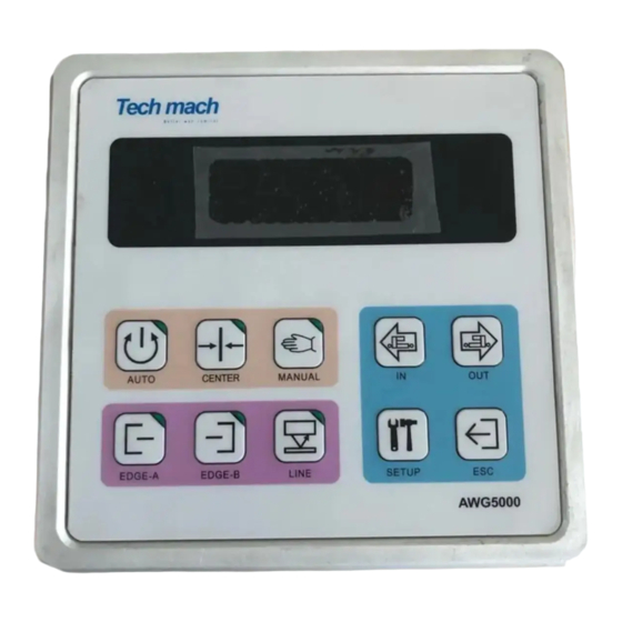
Technical Data 1.Web Guiding control enclosure Power supply: 24VDC 1%,12VDC 1%; Rated power consumption:120VA; Enclosure: Protection class is IP54, embedded installation mode and wall-hanging installation mode is optional; Splice performance: remote control allowed; On-board entry keypad function: Parameter setting Edge A select Edge B select Centerline select Actuator Retract... - Page 10 3.Linear Actuator Mode: Max end-of-travel: Max load rating: 1500 3000 Max Thrust Example of confirming the parameter: Type Load End-of-travel...
-
Page 11: Installation And Adjustment
Installation and Debugging Installation: Note: Make sure NO any electrical connections exits before the mechanism installation. 1).Control Enclosure (Refer to application drawing on appendix I) Install the control enclosure on a rigid mount such as a wall or secure framework. Don’t install the control enclosure on the side of a dryer or in other high temperature areas. - Page 12 To simplify installation and adjustment, we suggest users select the auxiliary brackets supplied by TECHMACH. The sensor cable should be long enough so that the sensor may be repositioned if the web width or web path changes.
- Page 13 4).Switch power supply Terminal Name Terminal code wiring color blue Green Brown Yellow User’s wiring CAUTION: Make sure the terminal earthed with PE( protect earth) completely. Adjustment Refer to connection drawing of Appendix V to complete the whole electric connection. Static Test a).Turn the power switch on;...
- Page 14 Edge Detector: Place at the edge of the web. The edge detector’s null indictor LED will turn off when the edge detector is positioned correctly. The scribed lines on the edge detector indicate the approximate location of the detector’s guide point.
-
Page 15: Operation
Operation The AWG5000 may be configured for a wide variety of applications, but most configurations share the same basic operating procedure: 1).Press the Center button and wait for the web guide to drive to the center of travel. 2).Thread the web through the machine. - Page 16 4).Sensor’s operation modes, see configure of parameter 10 for more information. 5).Press AUTO button. The system will now guide the web in Auto mode. 6).System configuration: a).verify the wiring connection carefully before turning on the power supply. b).Note that the LED display will show dashes ‘- - - - -’ immediately after power is turned on, the dashes indicate that no parameter is currently selected for examination or adjustment, but that the system is operating normally.
-
Page 17: Aw5000 Control Enclosure
Press SETUP to store the new data value in non-volatile memory; To leave the data value at its original value press ESC; 4).Operating modes: (AUTO): AUTO MODE; (CENTER): CENTER MODE; (MANUAL): MANUAL MODE. The parameters of AWG5000 control enclosure are described below: 0).Web compensation enable bit. Parameter code number:00... - Page 18 1).Input A Polarity Parameter Code number: 01 Parameter Range: [0, 1], the default value is 0 0 — The actuator will move out when edge detector A is blocked, or the Eagle Eye I sensor’s sight point is to the left of the line or edge it is following.
- Page 19 7).Manual Polarity Parameter code number: 07 Parameter range: [0, 1], the default value is 0 0 — The actuator extends when the OUT mode is selected, and retracts when the IN mode is select 1 — The actuator extends when the IN mode is selected, and retracts when the OUT mode is selected 8).Power-up Mode Parameter code number: 08 Data: [0-2], the default value is 0...
- Page 20 13).reserved for future use Parameter code number: 13 14).reserved for future use Parameter code number: 14 15).reserved for future use Parameter code number: 15 16).reserved for future use Parameter code number: 16 17).Recover the factory configure Parameter Code number: 17 Parameter range: [0, 1], the default value is 0 0 –...
- Page 21 23). High signal level of sensor guide point Parameter Code number: 23 Parameter range: [0-9], the default value is 5 Read only. 24). Low signal level of sensor guide point Parameter Code number: 24 Parameter range: [0-99], the default value is 12 Read only.
- Page 22 30).reserved for future use Parameter code number:30 31).reserved for future use Parameter code number: 31 32).reserved for future use Parameter code number: 32 Parameter Range: [0-1],the default value is 0 0-disabled PLC Interface 1-Enabled PLC Interface,now that the automatic web guiding is controlled by external input PLC Signal. 33).reserved for future use Parameter code number: 33 34).reserved for future use...
- Page 23 43).reserved for future use Parameter code number: 43 44).reserved for future use Parameter code number: 44 45).reserved for future use Parameter code number: 45 46).reserved for future use Parameter code number: 46 47). Web code Parameter code number: 47 Parameter Range: [0-31], the default value is 0, the corresponding software version is P1.13 This software can store up to 32 unique job parameters, user can select required job parameter by adjust this parameter.
-
Page 24: Troubleshooting
Troubleshooting 1.The system will not work in automatic, Manual, or Servo-Center mode Reason and solution Open line fuse. If the LED data displays are not lit, check the line fuse and replace if open. If the replacement fuse also opens, the system must be returned for repair Inhibit input polarity is set wrong. - Page 25 4.The actuator extends or retracts beyond the actuator’s end-of-travel limits and jams Description and solution: Limit Switch or encoder failed. Replace the limit switch or encoder. 5.The system will not work in Automatic mode but works correctly in Manual and Servo-Center mode Description and solution: Edge detector: Transducers covered with dust or other material.
-
Page 26: Maintenance
Maintenance Please operate and deposit this mechanism under necessary environment conditions. Move and operate this mechanism with correct methods, as specified in this instruction. Make sure correct wirings connection as specified in this instruction, especially for wiring of power supply. After power-up, make sure correct parameter configure of the control enclosure before operation. -
Page 27: Warranty Policy & Server After Sale
Warranty Policy & server after sale Techmach products are warranted to be free from defects in design, materials and workmanship for a period of one (1) year from date of delivery. No other warranty is expressed or implied including warranties or merchantability and fitness for any particular purpose. - Page 28 Appendix .I: Application drawing for control enclosure installation...
- Page 29 Appendix II Edge detector application drawing...
- Page 30 Appendix III: Installation drawing for EAGLE EYE I photoelectric sensor...
Need help?
Do you have a question about the AWG5000 and is the answer not in the manual?
Questions and answers