Table of Contents
Advertisement
Quick Links
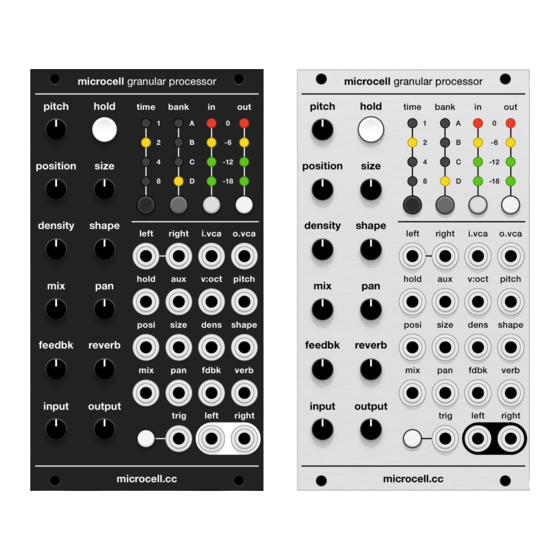
microcell granular processor
user manual + DIY build guide v1.0
For a full description of functionality, including firmware upgrades and
Calibration instructions, check the Supercell user manual at
grayscale.info/supercell – most details are identical. For a delineation of
the Superparasites firmware modes, check the microcell.cc website. For
documentation of the individual Parasites and Kammerl functions, see
mqtthiqs.github.io/parasites/clouds.html and kammerl.de/audio/clouds
and for basic functionality questions, check the original Mutable manual
for Clouds at mutable-instruments.net/modules/clouds/manual/
DIY Build Guide
This is a straightforward build with just a few quirks and a lot of solder
joints. Please review the steps below before starting your build.
1. PARTS COUNT. It's always a good idea to take inventory before starting
a build. You should have 19 jacks (with nuts), 11 pots, five tact switches
(with caps), one LED switch, and a total of 16 LEDs (two red, four green,
ten yellow), plus one front panel, one front panel PCB, one SMD
subassembly, and one power cable. If anything is missing or damaged,
please send an email to info@microcell.cc and we'll respond ASAP.
2. HEADERS. Attach the unsoldered headers to the rear PCB, then fit the
headers to the unpopulated front PCB. This ensures good alignment
between the two boards. Solder one pin on each end of each header, then
separate the assembly and solder the remaining header pins. This keeps
the SMD board from being accidentally damaged during soldering.
3. TACT SWITCHES. Solder the five tact switches in place. They do not
have a specific orientation and can be installed either way.
Advertisement
Table of Contents

Summary of Contents for microcell granular processor
- Page 1 PCB, one SMD subassembly, and one power cable. If anything is missing or damaged, please send an email to info@microcell.cc and we’ll respond ASAP. 2. HEADERS. Attach the unsoldered headers to the rear PCB, then fit the headers to the unpopulated front PCB.
- Page 2 4. JACKS. Fit the LEFT input and RIGHT output jacks to the PCB and solder all three pins of each jack. Fit the remaining jacks in place (some jacks have the ground pin slightly offset due to adjacent headers). Fit the panel to the jacks and hand-tighten a nut onto the L IN and R OUT jacks.
- Page 3 10. CALIBRATION. The SMD subassembly is tested and calibrated at the factory, so this step is not required. Calibration will only be required if you update the firmware or decide to install the “Core” firmware. microcell ships with the “Superparasites” firmware installed by default. If you need to recalibrate, check the Supercell manual at grayscale.info/supercell for...
- Page 4 (CC BY-SA 3.0 and the MIT License, respectively). The CC BY-SA 3.0 license grants a broad range of rights related to the Supercell/microcell source files but it does not grant any rights to use intellectual property such as trademarks, brand names, and logos.
Need help?
Do you have a question about the granular processor and is the answer not in the manual?
Questions and answers