Table of Contents
Advertisement
Quick Links
Advertisement
Table of Contents

Summary of Contents for Xima L100
- Page 1 USER MANUAL XIMA Inverter L100 Version 1.0...
-
Page 2: Table Of Contents
Mechanical and Safety System ................7 Fire ........................7 Fuses and Protective Circuits ................7 Overload range ....................7 Unique Features of Xima L100 ................... 9 Device Installation ......................13 Installation Location ..................13 Characteristics of Device Installation Location ............ 15 Motor ...................... - Page 3 Faults ..........................49 Warranty and After-Sales Services..................53 Warranty Voidance Conditions ................53 Options and Customized Parameters ................53 Quick Installation of Xima Inverter ................... 54 Open-loop Installation ..................54 Quick Access Parameters Table ..................55 Initial Parameters .................... 55 Rated Parameters ....................
-
Page 4: Introduction
Introduction Thank you for choosing the Xima inverter device. Please carefully read the contents of this manual not only to make a quick and safe installation, but also to make the use of our company's warranty service. In spite of the specialized terminology and concepts used in this manual, it is useful for those who have minimum information about installing power inverter devices. -
Page 5: Device Accessories
7.5/5.5 3/380 5~120/1300 Table 1: Power input/output characteristics of various models of Xima L100 • The brake power resistance presented in Table 1 is given regarding the coefficient of 10% for energy reverse, and for systems with a higher reverse, the braking resistance must be selected proportionally larger, but range of the resistance does not change. - Page 6 Input frequency 47 – 63Hz Input voltage 330 – 460(3Φ) Output voltage 0 – Input Voltage Efficiency (PF=1, Vout=Vin, Iout=12) > 98% Phase short circuit protection To Phase, Ground, +Bus, -Bus Maximum starting torque < 150% Inrush current <10A Brake DC Brake, Dynamic Brake Voltage limit threshold 700V...
- Page 7 Fig. 1: Geometry of the device Device Weight Model (gr) > XIMA-B 91.5 194.5 2200 Table 3: Physical characteristics of Xima L100...
-
Page 8: Safety Tips
Safety Tips General Tips Observance of safety tips not only will eliminate possible dangers during installation and use, but also it will result in longer lifetime and more continuous performance for the device. Non- compliance with these tips, causes potential life-threatening or financial risks. Note that the installation of this device requires expertise and specialization, and non-specialist personnel are never allowed to install and set up the device, and corresponding personal injury and material damage is the responsibility of the consumer. - Page 9 If the current exceeds 200% of the rated current, the device will demonstrate an over-current fault right away. Overload Duration of overload fault Duration of overload output current from cold installation fault from rated load to input current (seconds) (seconds) 115% 120% 130%...
-
Page 10: Unique Features Of Xima L100
Unique Features of Xima L100 Xima is designed based on reduced cost and time of installation and also, increased lifetime and efficiency. 8 Previously Defined Brake Inputs Sequence 4 Digital Special To Outputs Elevator Remove Automatic Xima L100 second Learning... - Page 11 According to EN-81 standard, one or two inverter output contactors can be removed under special condition. Xima L100 elevator inverters provide this condition by receiving safety circuit on Enable (I8) input and sending an Enable (OP2) feedback on the output.
- Page 12 • Quick and easy installation: The Xima inverter is designed in a way that if you properly connect the inputs, and appropriately link the outputs to the control panel contactor, by pressing ENTER you can make the inverter ready to work, only with three parameters related to the distance between the magnets, and the motor rated current.
- Page 13 • Lifting Brake Sequence: The order of brake release in Xima inverter based on various commands is as follows: Brake Brake Start Speed Delay Delay <1s 0.1s Brake off Delay Start Brake Contactor Enable Fig. 3: The order of brake release in Xima L100 ...
-
Page 14: Device Installation
Device Installation Installation Location One of the most important factors in the failure of the motor speed control system is the non- observance of the relevant principles at the installation location, which in some cases could result in warranty voidance. The device must be installed inside a standard metal control panel and this panel must have a suitable ventilation. - Page 15 - The use of air filter in the air inlet of the control panel, especially in unclean and dusty areas is mandatory, and the excessive dust inside the device will invalidate the warranty. - Any direct and dense humidity (such as dew) can cause a lot of damage to the device and this device will not be subject to warranty of replacement and repair.
-
Page 16: Characteristics Of Device Installation Location
Characteristics of Device Installation Location The table below shows the minimum characteristics of the installation location for the stable and reliable operation of the device. Note that non-observance of the following points will cause the device to function incorrectly and possible consequences are beyond the responsibility of the company. Installation Inside the control panel with suitable ventilation and filter, and in a covered Location... - Page 17 and close the screws of the bottom of the device (do not completely close), and then tighten (completely close) the four screws as is necessary. Note that you should also use the washers with the screws. To speed up the installation and to make it easy, it is better to be done by two people. Washer 4 mm drive screw Fig.
-
Page 18: Electrical Installation
Fig. 6: General schematic of Xima The Xima device has a row of 18 command terminals at the upper part and 9 power terminals at the lower part. Wire the inverter, motor, and other related equipment as shown below. At the top, power terminals are displayed separately from the control terminals. -
Page 19: Power Terminals
Power Terminals Brake resistance Fig. 8: Illustration of input and output power terminals Three Phases (380V) Power inputs R, S, T Power outputs W, V, U XIMAE100XYYY-Ph KW/V Cross sections for input wire/output wire (mm XIMAL100B075-3 7.5/380V 4 / 5.5 Table 6: Proper cross sections for input/output Important points Note that it is not necessary to connect the null to the N input. -
Page 20: Command Terminals
Do not use a miniature or thermal switch on the output of the device. Connect the ground input, if possible, in order to prevent the output noise and the possibility of electric shock. It is not mandatory to use the harmonic reduction inductance and the input/output noise filter. - Page 21 COM terminal of the inverter.) 12V output ground to feed the sensor or 200mA other similar components. RELAY-1 Contactor Relay 250V/1A Special relay for connection to the contactor According to the standard, this unique feature of the Xima inverter, converts two electromechanical elements required...
- Page 22 Terminal Name Function Allowable range before the motor to one mechanical element (contactor 1) and one inverter output relay. In fact, the Xima inverter becomes Contactor Less, and according EN81 standard, places electromechanical elements before the motor for more safety .
-
Page 23: Wiring Contactors With Enable Feedback In N.c Mode
Wiring Contactors with Enable Feedback in N.C Mode Wiring Contactors with Enable Feedback in N.O Mode Control Panel Enable Feedback Input Feedback Fig. 10: Wiring the contactors with Enable feedback... - Page 24 Brake Resistance RJ45 Enable Feedback 12V Output Up Command Down Command Fault input of the control panel Fault Output Leveling Speed Relay 3 Inspection Speed Intermediate Speed Brake Normal Speed Relay 2 Rescue Speed End of safety circuit (68) Enable Input Contactor Relay 1 Safety circuit common (COM)
-
Page 25: Rescue Mode
Rescue Mode In this Mode, which occurs in power outage, the inverter input must be disconnected from the urban electricity, and must be connected to the UPS by a two-way R and T input contactor. In this case, the inverter operates according to the parameter setting . Moreover, the maximum permissible UPS output power must be specified by the parameter ;... -
Page 26: Software Setting
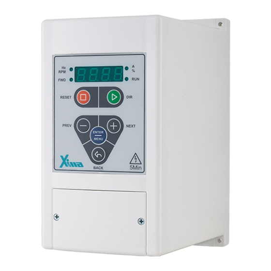
Software Setting Keyboard and Screen The XIMA device has a 4-digit screen and 4 LED lights for displaying values and parameters, and a 6-key keyboard for setting parameters, resetting faults, and starting or stopping the motor. Fig. 14: Main keyboard of the device... -
Page 27: Screen
BACK Back is used to exit from each step when setting parameters. Table 8: Introduction of keyboard and screen of the Xima device Screen When the device is turned on, firstly all LEDs and screen segments are turned on for 0.5 second, then the word ... - Page 28 Enter Password (when a password is set) Back ENTER Without password Last edited parameter ENTER Saved ENTER Back ENTER Without Save Back ENTER Saved Set value of parameter Parameter menu Parameter Submenu Fig. 15: Setting parameters of the Xima device...
-
Page 29: Method Of Parameter Settings
Method of Parameter Settings - First press Enter and release it to go to the parameters page. - If you have set the parameter (password), you must first enter the password and then press Enter to go to the Parameters page (If is not zero, enter the password and press Enter). -
Page 30: Parameters
In this category, fault values the parameters are read-only. Table 9: Parameters categories of Xima-L100 device Note that the number of parameters is not continuous which is because we may add some parameters in future versions of the device. -
Page 31: Initial Parameters
Initial Parameters Parameter Name Setting range Default Type Normal Speed 0.00-2.50 m/s 1.00 Normal speed in the elevator speed settings Intermediate Speed 0.00-2.50 m/s 0.50 Intermediate speed in the elevator speed settings Inspection Speed 0.00-2.50 m/s 0.30 Inspection speed in the elevator speed settings Leveling Speed 0.00-2.50 m/s... - Page 32 Distance between the low-speed magnet and the floor level 0.0-50.0 cm Half of the distance between leveling magnets Stop Method Xima uses two methods for stopping 0 – Distance approach using parameters and 1 – Deceleration approach using parameters to Deceleration 0.00-1.50 m/s...
- Page 33 Fig. 18: Brake Sequence in Xima inverter Brake Brake Start Speed Delay Delay <1s 0.1s Brake off Delay Start Brake Contactor Enable Brake on Delay 0.0-3.0 s Delay time in the beginning of the movement, from the time of brake on to the time of start command in seconds.
-
Page 34: Rated Parameters
Fig. 19: Speed vs. time diagram of the elevator Initial Acceleration 0.1-3.0 m/s Initial Acceleration in m/s 0.000-0.300 Initial Speed 0.01 ... -
Page 35: Inputs And Outputs
Parameter Name Setting range Default value Type Motor Rated Frequency 5.0-500.0 Hz 50.0 Motor Rated Frequency Rated (Nominal) Speed 0.00-2.50 m/s 1.00 Rated Speed Default Motor Direction Default Motor Direction Low-speed Gain 0.50-1.20 1.00 Low-speed Gain Motor Power 1.0-7.5 kW ... - Page 36 Parameter Name Setting range Default value Type Multi speed 4 Multi speed 5 Multi speed 6 Multi speed 7 2 & 3 - Serial communication method In this method, different speeds are selected by the control panel using the serial communication between the control panel and the inverter.
- Page 37 Parameter Name Setting range Default value Type Parameter settings from to must be done as table below. Relays and digital outputs settings Contactor command Brake command Fault happening (Digital output N.C is disabled when inverter fault is happened) Feedback Enable output (Digital output N.C is disabled when a ...
-
Page 38: System Parameters
Parameter Name Setting range Default value Type Multi Speed 3 0.00-2.50 m/s 0.30 Multi Speed 3 Multi Speed 4 0.00-2.50 m/s 0.50 Multi Speed 4 Multi Speed 5 0.00-2.50 m/s 0.70 Multi Speed 5 Multi Speed 6 0.00-2.50 m/s 0.80... - Page 39 using Xima USB-485 interface module and Xima Firmware Upgrade software. If by mistake jumped into the bootloader, just power off/power on the device and the device will reset to the normal state.
-
Page 40: Protection Parameters
Parameter Name Setting range Default value Type UPS Power/Rescue Power 0.2-20.0 kW 2.0 kW/0.5 kW If the Pd03 parameter is equal to 1 or 2, Pd04 will determine the maximum permissible power from the UPS in the rescue mode. This ... -
Page 41: Monitoring Parameters
Parameter Name Setting range Default value Type Small Motor This parameter is used for enabling or disabling the small motor fault. When the motor output current is less than the inverter's rated values, the device shows this fault based on the inverter's internal parameters. No. -
Page 42: Displaying Faults History
Displaying Faults History Parameters Explanations Type Last fault of the device Fault before parameter Hi01 Fault before parameter Hi02 Fault before parameter Hi03 Fault before parameter Hi04 Fault before parameter Hi05 ... -
Page 43: Monitoring Functions
Monitoring Functions When the inverter is functioning normally, you can see the various output parameters of the inverter by pressing Up or Down. Changes of the Screen and LEDs Functioning Output frequency of the device in Hertz Hz/RPM . (dot and Hz/RPM light will turn on) Output current from 0.00 to 20.00 Amps. -
Page 44: Parameters Of Monitoring Menu
Parameters of Monitoring Menu Parameter Application Displayed Parameter Type PG01 Input Terminal status Enabled Inputs PG02 Output Terminal status Enabled Outputs When access to this list is enabled, you can see some of the output parameters, settings and enable status of the inverter's input/output on the screen . -
Page 45: Stop Mode Function
Stop Mode Function The Xima inverter has two methods for stopping at the floors. In the first method (Distance Mode), the inverter selects exactly the best speed and deceleration to stop at the floor, by entering the distance between the low-speed magnet and the floor level, and half the distance between the two leveling magnets. - Page 46 Deceleration 0.00-1.50 m/s 0.70 Jerk 3 0.00-0.50 m/s 0.80 Jerk 4 0.00-0.50 m/s 0.80 Fig. 22: Stopping the elevator with the Xima inverter and the related parameters...
-
Page 47: Installation With Quick Menu
Installation with Quick Menu In this section, the easy installation process for XIMA inverters, will be described for an ordinary user in a step-by-step process. The Quick Menu is a three-parameter menu which we can access by pressing Enter for 3 seconds. In this menu we can set the rated current of the motor, the distance from the low-speed magnets to the floor, and the landing distance, respectively. -
Page 48: Possible Problems
Possible Problems Problem Cause How to fix Carefully check the input electricity in the terminals The device not - No electricity at the device input by a voltmeter. If there is being turned on - Device failure enough voltage, quickly cut off the electricity and send the device for repair. - Page 49 Problem Cause How to fix parameter) from the second menu. First, increase Jerk 1 () gradually. If the vibration is not removed, increase the Vibration of the ACC acceleration cabin when It is required to set the Jerk1 and parameter () . starting the Acceleration parameters.
-
Page 50: Faults
Faults If a fault occurs for the device, the output of the device will be quickly disconnected and the corresponding fault message will be displayed. There are 3 ways to reset the fault state: 1 - Pressing the Reset key to reset the fault after 5 seconds. 2 - Disabling the Enable command 3 - Stopping the inverter (In the case of a fault occurrence during the device operation). - Page 51 Number Fault Fault Code Possible Cause - High voltage input - The motor moving to the generator mode by mechanical load Over Voltage Checking the input voltage Using Brake Resistance - Short circuit or overcurrent from the 12V terminal to the COM ...
- Page 52 Number Fault Fault Code Possible Cause - High temperature of installation environment - High switching frequency - Fan failure - High load on the motor - Proximity to the source of heat Over Temperature - The fan and the heat sink of the device being dirty Check the ambient temperature.
- Page 53 Number Fault Fault Code Possible Cause disconnected. Also, we will see this fault if the low- RPM wiring of the motor is connected to the inverter . Check and parameters. - Current drop fault When the motor contactor is disconnected and the Current Drop Fault current is cut off at once.
-
Page 54: Warranty And After-Sales Services
Warranty and After-Sales Services Xima pays special attention to its after-sales support, and its goal is to present the fastest after- sales service to its customers. The smart and optimal design, the production of all of the boards by the company itself, and the use of original and up-to-date components, not only has improved the quality of the device, but also has greatly reduced the cost of failures and repairs. -
Page 55: Quick Installation Of Xima Inverter
= X0 = Distance from walking to the floor level Determining jerks and acceleration pa11 = acceleration pa12 = jerk at the beginning of the acceleration pa13 = jerk at the end of the acceleration Fig. 24: Open-Loop-Installation guide of the Xima inverter... -
Page 56: Quick Access Parameters Table
Quick Access Parameters Table Initial Parameters Parameter Name Setting Range Default Value Type Normal Speed 0.00-2.50 m/s 1.00 Intermediate Speed 0.00-2.50 m/s 0.50 Inspection Speed 0.00-2.50 m/s 0.30 Leveling Speed 0.00-2.50 m/s 0.10 Acceleration 0.00-1.00 m/s 0.50 ... -
Page 57: Inputs And Outputs Parameters
Parameter Name Setting Range Default Value Type Low-Speed Gain 0.50-1.20 1.00 Motor Power 1.0-7.5 kW Motor Pole pairs 1-50 Motor RPM 30-9999 RPM 1460 Motor Power Factor 0.20-0.90 0.50 Inputs and Outputs Parameters Parameter Name Setting Range Default Value Type... -
Page 58: Protection Parameters
Protection Parameters Parameter Name Setting Range Default Value Type Input Phase Loss Output Phase Loss Motor Over Load 30-300% 100% Brake Resistance 30-300 ohm Brake Power 50-9999 Watt 1300 Over Current Trip 1.0-20.0 A 18.0 Level Over Current Trip... - Page 59 Fault before parameter Hi06 Count of short circuit faults (SC occurrence) Count of OC-OCA-OCD fault occurrences Count of over-heat faults (OH occurrence) Count of over-voltage faults (OV occurrence) Count of over-power faults (OP occurrence) ...
Need help?
Do you have a question about the L100 and is the answer not in the manual?
Questions and answers