
Summary of Contents for Flowmasonic WUF100 CF Series
- Page 2 Welcome to use the new generation ultrasonic flow meter made of our patented technology. WUF 100 CF Series Ultrasonic the transit time principle to measure the velocity of relatively clean liquids in full pipes. The purpose of this guide is to provide installation procedures and basic operating instructions for WUF 100 CF Series Ultrasonic Flow/Heat Meters.
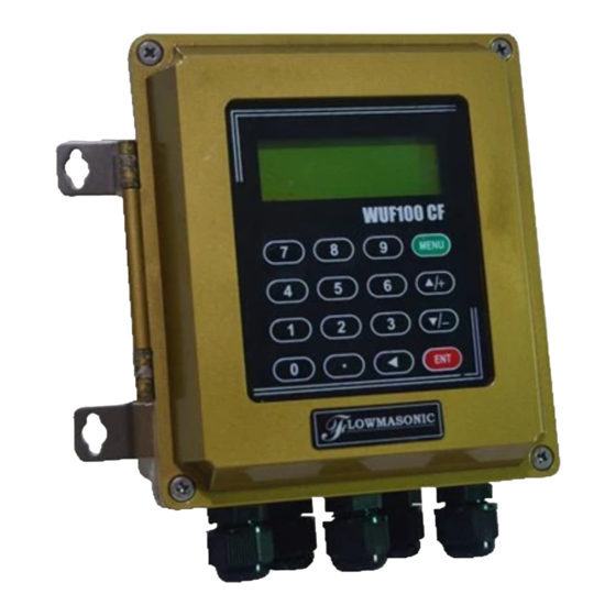
- Page 3 Measuring Diagrams 3.1 Separated Mounting Clamp On Inline 3.2 Fixed Mounting Clamp On Inline Converter Installation and Wiring Diagram 4.1 Separated Mounting · WUF100 CF Dimention...
- Page 4 · Wall mounting: Fix the converter with 4 6 expansion bolts or normal nails · DIN-rail mounting by using rail fixing clamps · DIN-rail mounting by using PCB bracket · Converter of WUF100 CF can be installed on the wall or in distribution box and explosion proof box ·...
- Page 5 · WUF 100 CF Wiring Diagram Thickness: 75mm Thickness: 165mm Wall moun ng:Fix the onverter Explosion-proof grade: DⅡBT5 with 4 Φ6 expansion bolts. Fix the converter with 4 Φ8 expansion bolts. 4.2 Fix mounting...
- Page 6 The converter is generally installed on the pipeline, sometimes installed on the wall of a well to avoid water immersion. WUF-100 IR Wiring Diagram · Open the back cover and complete the wiring. To avoid leaking, please tighten the water joint and screws of the back cover after wiring. Be sure not to open the front cover.
- Page 7 Separated Mounting are used for inputting numbers or menu numbers. is used for back left or delete the left character. are used for entering into the last and next menu. Also can be used as ± sign when inputting numbers. is used for accessing the menu.
- Page 8 Display today’s total NET flow Input outer perimeter *M11 Input outer diameter. Available range is 0 to 18000mm *M12 Input pipe wall thickness. *M13 Input inner diameter *M14 Select pipe material Input sound velocity of the pipe material Select lining material Input sound velocity of the lining material Input the lining thickness Input the absolute roughness of pipe inner wall...
- Page 9 Zero calibration/Zero point setup. Make sure the liquid in the pipe is not running while doing the setup. Clear the zero point value, and restore original value. Manual Zero point . Set up a flow bias. Generally this value should be 0. Flow rate scale factor.
- Page 10 AI4 value range. Used to enter temperature/pressure values that are corresponding to 4mA and 20mA input current. AI5 value range. Used to enter temperature/pressure values that are corresponding to 4mA and 20mA input current. Setup the frequency range (lower and upper limit) for the frequency output function. Valid range is 0Hz-9999Hz.
- Page 11 The built - in batch controller Set the flow batch value(dose) The internal output of the batch controller can be directed either to the OCT or the RELAY output circuits. M81 and M80 should be used together to configure the batch controller. Note: Because the measuring period is 500mS, the flow for every dos should be keeping at 60 second long to get a 1% dose accuracy View the daily, monthly and yearly flow totalizer and thermal energy totalizer value.
- Page 12 This is not a window but a command for the thermal printer to advance 5 lines paper. This is not a window but a command to print the pipe parameters. By default, the produced data will be directed to the internal serial bus (thermal printer).
-
Page 13: Transducers Installation
Accurate measured parameters can have a great influence on measuring precision and reliability. It is suggested to measure the practical perimeter and wall thickness of the pipeline. Ultrasonic thickness gauge can be used to measure the pipe thickness. Measured parameters setup is from Menu10 to Menu29. Please complete one by one. >>>... - Page 14 >> Shaking There cannot be obvious shaking on the installation point, otherwise it needs to be tightened. >>Steady flow Steady flow is helpful for ensuring measurement accuracy. Standard requests for steady flow are: 1. The pipe should be far away from pump outlet and half open valve.
- Page 15 >>Pressure The maximum press ure for standard insertion and inline transducer is 1.6MPa Out of this range need customized. >>EMI (electromagnetic interference) The ultrasonic flow meter, transducer and signal cable can be easily interfered by interference sources such as frequency changer, radio station, microwave station, GSM base station and high-tension cable.
- Page 16 >> Z method DN6000. Als o can be used when V Z method should be priority selected for pipe sizes DN200 method doesn’t work well. Make sure the vertical distance of two transducers equals to the installation distance, and the two transducers are on the same axis surface. 3) Positioning installation points >>...
- Page 17 4) Clean the surface of installation points Paint, rust and anticorrosive coating on installation points need to be cleaned. It’s good to use a polishing machine to get the metal luster. As shown below: 5) Install transducers After transducer wiring and sealing, please evenly smear 2 3mm couplant on the transducer emitting surface.
- Page 18 >> Z method Z method can be used for all pipes > DN50mm. Make sure the vertical distance of two transducers equals to the installation distance, and the two transducers are on the same axis surface. The transmit direction mush be opposite. >>...
- Page 19 3) Positioning installation points >> V method The line between two transducers is parallel to pipe axis, and equal to the distance shown in the converter. As shown, A, B are the two installation points. >> Z method 1. Firstly according to the installation distance shown in converter, positioning two points A, C on the same side of pipeline.
- Page 20 >> Pipe hoop Fix For pipes can’t be welded directly like cast iron pipe, cement pipe, copper pipe and composite pipe, customized pipe hoop is recommended. The hoop center should be overlapped with the transducer installation point. Please compress the sealing gasket tightly to avoid leaking. 5) Open hole After finishing the installation of ball valve and base, insert the open hole tool into ball...
- Page 21 >> Transmit directon There is a indicatng arrow on the transducer junccon box, the arrow directon on two transducers should be opposite and parallel to the pipe axis. >> Operation steps · Tighten the locknut into ball valve, adjust the insertion depth scale. Open ball valve, completely push in the upstream transducer rod.
-
Page 22: Finish Installation
2) Check installation Please see details in Chapter 7.5 Check Installation The flow meter includes the detection ability. M90 is used for checking signal strength and quality. M91 is used for checking the ratio of measured and theoretical transmission time (transmission time ratio). - Page 23 Also Provide : fire pump test meter electromagnetic coriolis flow meter flow meter level sensor & level switch connectors Page 22...