Table of Contents
Advertisement
Quick Links
Operation Manual
The new and unique PFM FLEX Concept comprises 4 different Instruments for Flow
and Pressure measurements. From the simplest Flex 1 to the most advanced
Flex 4.
The differences are based upon the functions in respective instrument.
Below is a summary of the available functions of the alternative Flex instruments.
Function
-Measuring Method 1 & 2
-Valve Library
-Save
-Switchmode
-Graphical Presentation
-Set-Value
-Media
-Energy & Power (2 temp measurements)
-Log Function
-Scope Presentation
Upgrading from FLEX 1 to FLEX 2 or to FLEX 3 or from FLEX 2 to FLEX 3 is easily
done by changing a memory stick in Hand terminal. Changing to FLEX 4 requires
service at Smart Balancing Instruments workshop. Please contact your supplier.
PFM Flex 4
FLEX 1
x
x
FLEX Instrument alternative________
FLEX 2
FLEX 3
x
x
x
x
FLEX 4
x
x
x
x
x
x
x
x
x
x
x
x
x
x
x
x
1
1
Advertisement
Table of Contents

Summary of Contents for Smart Balancing PFM Flex 1
-
Page 1: Measuring Method
Upgrading from FLEX 1 to FLEX 2 or to FLEX 3 or from FLEX 2 to FLEX 3 is easily done by changing a memory stick in Hand terminal. Changing to FLEX 4 requires service at Smart Balancing Instruments workshop. Please contact your supplier. -
Page 2: Table Of Contents
Table of contents 1. Product description 1.1 General description page 3 1.2 Unpacking page 4 1.3 Technical data page 5 2. Handling page 6 3. Preparations – Measuring page 7 3.1 Measuring Sensor page 7 3.2 Hand-Terminal page 8 3.2.1 Settings page 10 3.2.1.1 Appearance page 10... -
Page 3: Product Description
Product description 1.1 General description PFM Flex 4 (PFM = Pressure Flow Meter) is an instrument for pressure- and flow measurements. The intended usage is checking- and documentation of water flow in heating- and cooling constructions. PFM Flex 4 consists mainly of a Measuring Sensor and a Hand Terminal (PPC) including the BalanceFlex program software. -
Page 4: Unpacking
Product description, cont’d 1.2 Unpacking. A complete PFM Flex 4 consists of: Carrying case Measuring Sensor Charger to Sensor 2 pcs Measuring hoses. 2 pcs Measuring needles Allen keys Manual CD with Manual and software for Balancing Measuring program, Valve browser, Report Viewer and links to useful programs Calibration protocol Hand Terminal with active... -
Page 5: Technical Data
Product description, cont’d Technical data, PFM FLEX Concept. Measurement Range - Total Pressure: max 2500kPa - Differential Pressure: 0-1000kPa. Optional: 0 - 2000kPa - Recommended pressure range: 3 – 200kPa - Static pressure: <1000kPa Optional: <2000kPa - Ambient temp: -30 - +40° C - System Temp T1: -30 - +120°... -
Page 6: Handling
Handling The instrument PFM Flex 4 is robust and easy to handle but should not be exposed to careless usage. Avoid exposing the instrument to temperatures below zero degrees C if there is water in the Sensor. To empty the Sensor just open the Sensor valve (by-pass position) and shake the Sensor. -
Page 7: Preparations - Measuring
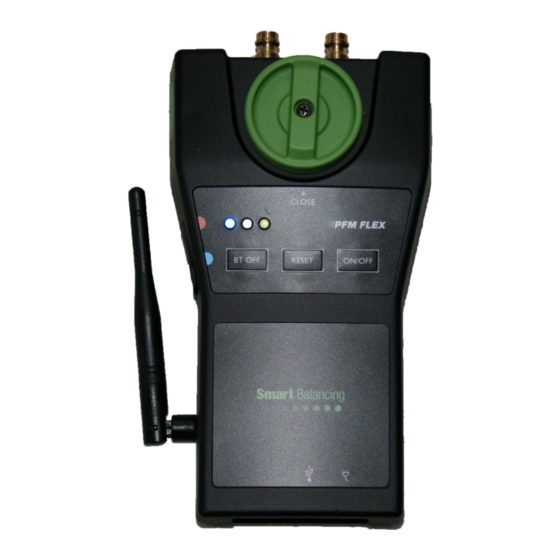
Preparations - Measuring Measuring Sensor. Start the Sensor by pressing the On/Off button. A green led indicates that the Sensor with its’ computer as well as Bluetooth transmitter is ”on”. Bluetooth connection to a Bluetooth object such as Handterminal is indicated by the blue led lighting. -
Page 8: Hand-Terminal
Preparations – Measuring, cont’d Hand Terminal. Before doing the settings you must start the Hand Terminal by pressing the On/Off button on the upper right of the Pda front. On the upper left there is a blue light which indicates the Bluetooth function of the Hand Terminal. - Page 9 Preparations – Measuring, cont’d Tap ”Start” or the MS symbol at the upper left to scroll down the program list. In the list, you will find ”BalanceFlex”. Tap ”BalanceFlex” in order to start the BalanceFlex measuring program. (For info regarding other programs and functions, please see the enclosed HP Manual).
-
Page 10: Settings
Preparations – Measuring, cont’d 3.2.1 Settings. Settings comprises 4 sub-menus (tabs). Appearance, Browser, Valve Data and License. Normally it is only Appearance and Valve Data that is to be set. 3.2.1.1 Appearance. Tap Appearance. Five settings are to be done. Language, and unit choices for DiffPressure, Flow, Static Pressure and Temperature. -
Page 11: Valve Data
Preparations – Measuring, cont’d 3.2.1.3 Valve Data. Under this tab, balancing valve measurements, are given a symbol or a denomination. The symbol will automatically be linked to the measurements that are saved. The first measurement that is performed and saved in the Hand Terminal will be allotted to the symbol chosen and completed with a current number. -
Page 12: Valve Data
Preparations – Measuring, cont’d 3.2.2 Valve Data. Tap at Valve Data at Main Menu. The Valve Data screen shows all stored balancing valve measurements. For example, if ”rv” has been chosen as symbol and five measurements have been completed and stored, the rv0, rv1,rv2, rv3 and rv4 icons will be seen on the screen. -
Page 13: Media
Preparations – Measuring, cont’d 3.2.3 Media Flowfactor. Media and associated correction factors are specific to manufacturer data, at the present water is set by default. When available, tap the arrow to the right, and choose the media from the drop- down box. -
Page 14: Function
Preparations – Measuring, cont’d 3.2.4 Function This menu consists of three tabs: Main, Offset calibration and Service. 3.2.4.1 Main Under Main you will find Function Test. The Sensor Data as well as the battery status of the Sensor is presented here. Sensor battery status and ”Name”... -
Page 15: Offset Calibration
Preparations – Measuring, cont’d 3.2.4.2 Offset calibration. Offset calibration is performed in order to bring a correct measurement of the Static pressure in a flow system. The calibration also brings higher accuracy when measuring diffpressure and flow. Offset calibration is performed when a Bluetooth connection between the Hand Terminal and the Sensor is established. -
Page 16: Measuring
Measuring As all functions and settings now are completed, we are prepared for the measuring procedure. The BalanceFlex program comprises two different measuring methods represented by 1 and 2 just below Measuring Methods. Measuring Method 1 is characterized by a given valve position, the measured differential pressure over a balancing valve and the corresponding flow calculation. - Page 17 Measuring – cont’d 4.1 Measuring Method 1. Tap 1 on the Main Menu of the BalanceFlex program. Tap the arrow to the right of the respective areas for Manufacturer, Model, Size, and Position and make your choices. Choosing Position generates automatically corresponding Kv- value.
- Page 18 Measuring – cont’d. Zeroing Follow the instructions which means open the sensor valve. Zeroing is now done over the balancing valve or the measuring object. Tap Continue and follow the new instruction i.e. close the sensor valve and tap Continue.
- Page 19 Measuring – cont’d. Following the last instructions you should now have the measurement menu visible with all data on display. On top you will see Flow which is calculated from the measured differential pressure (seen below Flow) and the actual Position (Kv- value).
- Page 20 Measuring – cont’d The window Save as is now displayed, including the measurement values. In the Save as- window you may denominate your measurement with other symbols then the ones chosen at ”Valve data” menu. (page 12) Tap the drop-down box and the available standard denominations are displayed as well as the keyboard.
- Page 21 Measuring – cont’d BalanceFlex Measuring program also comprises graphical presentation of the actual measurement. At the Measuring window there are two short-cut icons which open the graphical presentation. Above the graph you see the continuously measured differential pressure. The position of the valve is displayed on the x-axis.
-
Page 22: Scope, Power & Energy
Scope, Power & Energy Tap the Scope, Power & Energy icon to the right at the quick reference bar, tap scope. The x-max value can be changed using the terminal keyboard. To get a 1 hour on-line Log with a value taken every second set X-max to 3600. - Page 23 Scope, Power & Energy Tap the Scope, Power & Energy icon to the right at the quick reference bar, tap Power & Energy. Accumulated energy amount during the period is presented at the top right of the Energy Log.
-
Page 24: Measuring Method
Measuring – cont’d 4.2 Measuring Method 2. Tap at Measuring Method 2, select manufacturer, model etc in the same manner as at Measuring Method 1. Follow the instructions on the screen and perform the zeroing in the same way as at Measuring Method 1. When the zeroing is completed, a Flow Calculator pop-up window will appear. - Page 25 Measuring – cont’d Tap the valve icon to the right of the Position area. A new Set Position pop-up window is opened. Adjust the valve to the calculated position which is presented at the Set position pop-up. Check the flow and repeat the procedure until desired flow value is achieved.
-
Page 26: Transferring Data From Hand Terminal To Pc
Transferring data from Hand Terminal to PC. Data that has been stored in the Hand Terminal is available under Valve Data. Valve Data is easily transferred to PC for further processing as transcription etc. A CD containing, for instance, Support is included in each complete PFM Flex 4. The ”Support”... -
Page 27: Set Value & Balancing Projects
Set Value & Balancing Projects Set-Value function is another example of how the Smart Balancing concept Facilitates commissioning work. The Set-Value function enables the operator to store all pre-set values of a project into the Handterminal before going out on site. Once out on site, pre-set... - Page 28 Set Value & Balancing Projects Tap on Create Project and designate a Project name. Tap on OK. A Excel report document is opened.
- Page 29 Set Value & Balancing Projects State relevant Balancing project information, it could be complete as for ID 1-3 in the above example or parts of information as for ID 4-6. The information is obtained from the installation documentation and drawings. Valve ID must always be noted.
- Page 30 Set Value & Balancing Projects Synchronize your Hand Terminal with your PC. Instructions are available in ”Getting Started”. Tap on the right Sync Icon (PC to Hand Terminal). Select and mark the Project that is to be transferred to the Hand Terminal. Tap on Open and the Balancing Project information (Set-Values) in your PC is transferred to your Hand Terminal.
- Page 31 Set Value & Balancing Projects At the lower part of the screen to the right, among the quick reference Icons, there is a red Project icon. Tap the icon, select Project and the Valve ID numbers that earlier were transferred to the Handterminal are now seen (1).
- Page 32 Set Value & Balancing Projects There are two scroll buttons under the ”End” button. Choose Project and Valve ID. Use the ”step up & step down” button to move the cursor. Stored Set-Values for flow, position, DP, and Kv is shown in the blue area to the left. (1) Adjust the valve to the right flow and tap on ”Save”.
- Page 33 Set Value & Balancing Projects Tap on the left Sync button, Hand Terminal to PC (1). Choose ”Category name” in the ”Presentation” menu to the left at the top bar (2) Tap the green Excel icon to open the complete Balance Excel Report with measurements and remarks.
- Page 34 Set Value & Balancing Projects...
- Page 35 Set Value & Balancing Projects Tag the individual measurements. Click at Report to create a Non-Project Balancing report without any set values. Click right at the Folder window to create a new folder or a sub folder. Tag the individual measurements; Click and drag to move the valve package to another folder.
- Page 36 Set Value & Balancing Projects...
- Page 37 Set Value & Balancing Projects Click at ”File” followed by transcription format. Choose ”Landscape” and reduce the transcription size into a regular A4- sheet print out.
- Page 38 Set Value & Balancing Projects The simplest way to delete finalized measurements and projects that has been transferred and saved at Report Viewer for PC, is via synchronization of the Hand Terminal with PC. Tap at Explore followed by Valve Data. Mark all measurements and tap on delete. Tap the ”Set-Value”...
-
Page 39: Using Several Measuring Sensors
Using several Measuring Sensors. A great advantage of the PFM Flex 4 is the possibility of using several Sensors and one Hand Terminal. This might be the case when balancing via a partner valve. Connect and start the Measuring Sensors with the valves you want to balance (according to 3.1). -
Page 40: Switchmode
Switchmode Click at ”Settings” at the main menu and then choose Browser. Tag the box with Sensor:1 ID number and then tap OK. Choose Method 1 and valve, continue to the measurement menu. Adjust the flow and then tap the Switchmode icon. - Page 41 Switchmode Tag the box with the Sensor:2 ID number and then tap OK. Choose valve, continue to the measurement menu. Adjust the flow and then tap the Switchmode icon.
- Page 42 Switchmode The Bluetooth communication is automatically switched from Sensor:2 and back to the Sensor:1 measurement menu. Make further adjustments if necessary at Sensor:1 and switch back to Sensor:2.
-
Page 43: Using Several Hand-Terminals
Hand Terminals. The condition is however that each Hand Terminal really has the BalanceFlex program and a valid license. For additional licenses please contact the supplier. Accessories. Smart Balancing offers extra accessories and parts. Please see our website www.smartbalancing.com information. -
Page 44: Upgrading
The same data is also stored on the Smart Balancing CD; Support, Valve Data. If you need to complete your Hand Terminal with data of valves that... -
Page 45: Warranty & Service
Warranty & Service Smart Balancing Instrument AB offers up to 5 years warranty on Sensor. The condition for getting the benefit of the five years warranty is that the instrument is sent annually to Smart Balancing Instrument AB for necessary calibrations. - Page 46 Copyright © 2005 All rights reserved. Microsoft, Windows Mobile, are trademarks of Microsoft Corporation registered in United States and/or other countries. The BLUETOOTH trademarks are owned by Bluetooth SIG, Inc., U.S.A.
Need help?
Do you have a question about the PFM Flex 1 and is the answer not in the manual?
Questions and answers